warp/m service manual - ADB Lighting Technologies
warp/m service manual - ADB Lighting Technologies warp/m service manual - ADB Lighting Technologies
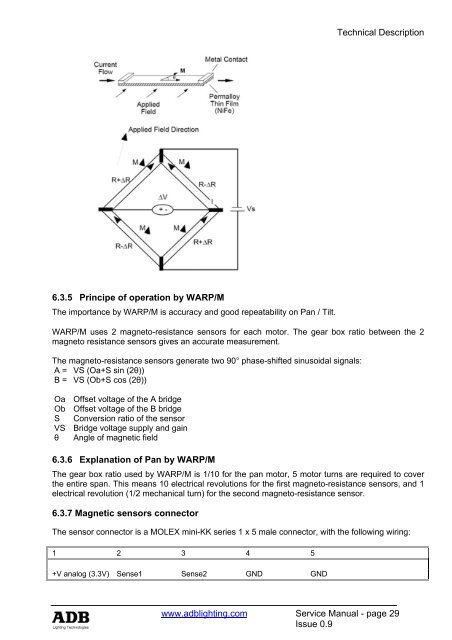
Technical Description6.3.2 Pan & Tilt driver board PCB 1525The Pan and Tilt drive are driven by 3 phase steppers. The steppers are PWM (Pulse withmodulated) controlled. We use a 1:10 belt drive reduction ratio to ensure a smooth Pan / tilt.The DSP is 8 bit processor dedicated to motor control. The DSP has a 10 channel A/D converterinput and a 6 channel PWM generator.6.3.3 Magneto-resistance sensorsA high resolution, low power magneto-resistance sensor is used. The MR sensor is capable ofmeasuring the angle direction of a magnetic field from a magnet.The MR sensor operates on 3 V with bandwidth response of 0 – 5 MHz.6.3.4 Principe of operation (1)Anisotropic magneto-resistance (AMR) occurs in ferrous materials. It is a change in resistance whena magnetic field is applied in a thin strip of ferrous material. The magneto-resistance is a function ofcos 2θ where θ is the angle between magnetization M and current flow in the thin strip. When anapplied magnetic field is larger than 80 Oe, the magnetization aligns in the same direction of theapplied field; this is called saturation mode. In this mode, θ is the angle between the direction ofapplied field and the current flow; the MR sensor is only sensitive to the direction of applied field.The sensor is in the form of a Wheatstone bridge (Figure). The resistance R of all four resistors isthe same. The bridge power supply VS causes current to flow through the resistors, the direction asindicated in the figure for each resistor. HMC1512 is designed to be used in saturationmode.HMC1512 has two identical MR bridges, coexisting on a single die. Bridge B physically rotates45° from bridge A. The HMC1512 has sensor output ∆V=VSS sin (2θ) for sensor A and sensor Boutput ∆VS=-VSS cos (2θ), where VS is supply voltage, S is a constant, determined by materials.(1) Honeywell Sensor productsService Manual - page 28Issue 0.9www.adblighting.com
Technical Description6.3.5 Principe of operation by WARP/MThe importance by WARP/M is accuracy and good repeatability on Pan / Tilt.WARP/M uses 2 magneto-resistance sensors for each motor. The gear box ratio between the 2magneto resistance sensors gives an accurate measurement.The magneto-resistance sensors generate two 90° phase-shifted sinusoidal signals:A = VS (Oa+S sin (2θ))B = VS (Ob+S cos (2θ))Oa Offset voltage of the A bridgeOb Offset voltage of the B bridgeS Conversion ratio of the sensorVS Bridge voltage supply and gainθ Angle of magnetic field6.3.6 Explanation of Pan by WARP/MThe gear box ratio used by WARP/M is 1/10 for the pan motor, 5 motor turns are required to coverthe entire span. This means 10 electrical revolutions for the first magneto-resistance sensors, and 1electrical revolution (1/2 mechanical turn) for the second magneto-resistance sensor.6.3.7 Magnetic sensors connectorThe sensor connector is a MOLEX mini-KK series 1 x 5 male connector, with the following wiring:1 2 3 4 5+V analog (3.3V) Sense1 Sense2 GND GNDwww.adblighting.com Service Manual - page 29Issue 0.9
- Page 1: Motorised WARPService ManualIssue 0
- Page 4 and 5: IndexIndexFOREWORD ................
- Page 6 and 7: Introduction1 IntroductionAbout Thi
- Page 8 and 9: Tools3 ToolsAdequate tools are requ
- Page 10 and 11: Spare Parts4.2 Spare Parts for the
- Page 12 and 13: Spare Parts4.2.2 Spare Parts for WA
- Page 14 and 15: Spare PartsConnector cable Power 10
- Page 16 and 17: Trouble Shooting5.2 Problems with T
- Page 18 and 19: Trouble Shooting5.4 Problems with S
- Page 20 and 21: Trouble Shooting5.5 Problems with a
- Page 22 and 23: Technical Description6 Technical De
- Page 24 and 25: Technical Description6.2.1 24 V Pow
- Page 26 and 27: Technical Description6.2.3 Boards D
- Page 28 and 29: Technical Description6.3.1.3 PCB 14
- Page 32 and 33: Technical Description6.3.8 Descript
- Page 34 and 35: Technical Description6.4 Wheels dri
- Page 36 and 37: Technical DescriptionFunctions:This
- Page 38 and 39: Technical DescriptionFunctions:This
- Page 40 and 41: Motorised Yoke7 Motorised Yoke - Ma
- Page 42 and 43: Motorised Yoke7.3 Open Motor WingRe
- Page 44 and 45: Motorised Yoke7.5 Replace Front Pan
- Page 46 and 47: Motorised Yoke7.7 Change Motor Boar
- Page 48 and 49: Motorised Yoke7.9 Replace PCB Shutt
- Page 50 and 51: Motorised Yoke7.11 Replace Top Box
- Page 52 and 53: Motorised Yoke7.13 Replace Coarse P
- Page 54 and 55: Motorised Yoke7.15 Replace Coarse T
- Page 56 and 57: Motorised Yoke7.17 Remove WARP from
- Page 58 and 59: Motorised Yoke7.19 Replace Tilt MOT
- Page 60 and 61: Motorised Yoke7.21 Remove Coarse TI
- Page 62 and 63: Motorised Yoke7.22.2 How to install
- Page 64 and 65: Motorised Yoke7.22.2.2 Left Motor W
- Page 66 and 67: Motorised Yoke7.24 Remove Yoke from
- Page 68 and 69: Motorised Yoke7.25 Replace Pan Belt
- Page 70 and 71: Motorised Yoke7.27 IR Sensor Settin
- Page 72 and 73: Motorised Yoke7.28 Motor WingRequir
- Page 74 and 75: Motorised Yoke7.30 Adjust Motors in
- Page 76 and 77: Motorised Yoke8.1.2 How to place th
- Page 78 and 79: Motorised Yoke8.3 Replace the Refle
Technical Description6.3.5 Principe of operation by WARP/MThe importance by WARP/M is accuracy and good repeatability on Pan / Tilt.WARP/M uses 2 magneto-resistance sensors for each motor. The gear box ratio between the 2magneto resistance sensors gives an accurate measurement.The magneto-resistance sensors generate two 90° phase-shifted sinusoidal signals:A = VS (Oa+S sin (2θ))B = VS (Ob+S cos (2θ))Oa Offset voltage of the A bridgeOb Offset voltage of the B bridgeS Conversion ratio of the sensorVS Bridge voltage supply and gainθ Angle of magnetic field6.3.6 Explanation of Pan by WARP/MThe gear box ratio used by WARP/M is 1/10 for the pan motor, 5 motor turns are required to coverthe entire span. This means 10 electrical revolutions for the first magneto-resistance sensors, and 1electrical revolution (1/2 mechanical turn) for the second magneto-resistance sensor.6.3.7 Magnetic sensors connectorThe sensor connector is a MOLEX mini-KK series 1 x 5 male connector, with the following wiring:1 2 3 4 5+V analog (3.3V) Sense1 Sense2 GND GNDwww.adblighting.com Service Manual - page 29Issue 0.9


