warp/m service manual - ADB Lighting Technologies
warp/m service manual - ADB Lighting Technologies
warp/m service manual - ADB Lighting Technologies
- No tags were found...

Create successful ePaper yourself
Turn your PDF publications into a flip-book with our unique Google optimized e-Paper software.
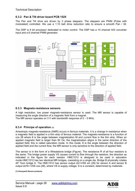
Technical Description6.3.2 Pan & Tilt driver board PCB 1525The Pan and Tilt drive are driven by 3 phase steppers. The steppers are PWM (Pulse withmodulated) controlled. We use a 1:10 belt drive reduction ratio to ensure a smooth Pan / tilt.The DSP is 8 bit processor dedicated to motor control. The DSP has a 10 channel A/D converterinput and a 6 channel PWM generator.6.3.3 Magneto-resistance sensorsA high resolution, low power magneto-resistance sensor is used. The MR sensor is capable ofmeasuring the angle direction of a magnetic field from a magnet.The MR sensor operates on 3 V with bandwidth response of 0 – 5 MHz.6.3.4 Principe of operation (1)Anisotropic magneto-resistance (AMR) occurs in ferrous materials. It is a change in resistance whena magnetic field is applied in a thin strip of ferrous material. The magneto-resistance is a function ofcos 2θ where θ is the angle between magnetization M and current flow in the thin strip. When anapplied magnetic field is larger than 80 Oe, the magnetization aligns in the same direction of theapplied field; this is called saturation mode. In this mode, θ is the angle between the direction ofapplied field and the current flow; the MR sensor is only sensitive to the direction of applied field.The sensor is in the form of a Wheatstone bridge (Figure). The resistance R of all four resistors isthe same. The bridge power supply VS causes current to flow through the resistors, the direction asindicated in the figure for each resistor. HMC1512 is designed to be used in saturationmode.HMC1512 has two identical MR bridges, coexisting on a single die. Bridge B physically rotates45° from bridge A. The HMC1512 has sensor output ∆V=VSS sin (2θ) for sensor A and sensor Boutput ∆VS=-VSS cos (2θ), where VS is supply voltage, S is a constant, determined by materials.(1) Honeywell Sensor productsService Manual - page 28Issue 0.9www.adblighting.com