

FM100 BROADCAST TRANSMITTER - Crown Broadcast
FM100 BROADCAST TRANSMITTER - Crown Broadcast
FM100 BROADCAST TRANSMITTER - Crown Broadcast
- No tags were found...

You also want an ePaper? Increase the reach of your titles
YUMPU automatically turns print PDFs into web optimized ePapers that Google loves.
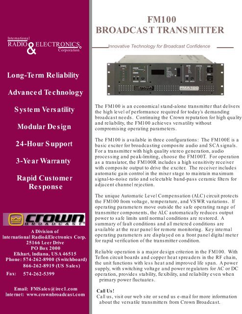
InternationalRADIO& ELECTRONICSCorporationC<strong>FM100</strong><strong>BROADCAST</strong> <strong>TRANSMITTER</strong>Innovative Technology for <strong>Broadcast</strong> ConfidenceLong-Term ReliabilityAdvanced TechnologySystem VersatilityModular Design24-Hour Support3-Year WarrantyRapid CustomerResponseA Division ofInternational Radio&Electronics Corp.25166 Leer DrivePO Box 2000Elkhart, Indiana, USA 46515Phone: 574-262-8900 (Switchboard)866-262-8919 (US Sales)Fax: 574-262-5399Email: FMSales@irec1.comInternet: www.crownbroadcast.comThe <strong>FM100</strong> is an economical stand-alone transmitter that deliversthe high level of performance required for today’s demandingbroadcast needs. Continuing the <strong>Crown</strong> reputation for high qualityand reliability, the <strong>FM100</strong> achieves versatility withoutcompromising operating parameters.The <strong>FM100</strong> is available in three configurations: The <strong>FM100</strong>E is abasic exciter for broadcasting composite audio and SCA signals.For a transmitter with high quality stereo generation, audioprocessing and peak-limiting, choose the <strong>FM100</strong>T. For operationas a translator, the <strong>FM100</strong>R includes a high sensitivity receiverwith composite output to drive the exciter. The receiver includesautomatic gain control in the mixer stage to maintain maximumsignal-to-noise ratio and selectable band-pass ceramic filters foradjacent channel rejection.The unique Automatic Level Compensation (ALC) circuit protectsthe <strong>FM100</strong> from voltage, temperature, and VSWR variations. Ifoperating parameters move outside the safe operating range oftransmitter components, the ALC automatically reduces outputpower to safe limits until normal conditions are restored. Asummary of fault conditions and all metered conditions areavailable at the rear panel for remote monitoring. Key internaloperating parameters are displayed on a front panel digital meterfor rapid verification of the transmitter condition.Reliable operation is a major design criterion in the <strong>FM100</strong>. WithTeflon circuit boards and copper heat spreaders in the RF chain,the unit functions with less heat and improved life span. A powersupply, with switching voltage and power regulators for AC or DCoperation, provides stability, flexibility, and reliability even whenprimary power fluctuates.Call Us!Call us, visit our web site or send us e-mail for more informationabout the versatile transmitters from <strong>Crown</strong> <strong>Broadcast</strong>.
Innovative Technology for <strong>Broadcast</strong> ConfidenceGeneralSpecificationsFrequency Range87 to 108 MHz (75 to 90 MHz Option Available)RF Power10 to 100 watts with front panel adjustmentRF Output Impedance50 Ohms unbalancedVSWR1.7:1 Maximum with automatic fold-back at higher VSWRFrequency StabilityBetter than +/-250 Hz over operating temperature rangeModulation TypeDirect Frequency Modulation of CarrierModulation Capability+/-75 KHzModulation IndicationLED Indicators with Peak indicatorsFM S/N Ratio (FM Noise)Better than 60 dB (70 to 80 dB typical)Asynchronous AM S/N RatioBetter than 55 dB with 100% modulation @ 400 Hz, no deemphasis,no FM modulation (typically > 60 dB)Synchronous AM S/N RatioBetter than 55 dB with 100% modulation @ 400 Hz, no deemphasis,FM modulation = 75 KHz @ 400 Hz (typically > 60dB)RF Harmonics/Spurious ProductsBetter than -70 dB (-80 dB typical)RF Bandwidth +/-120 KHz, better than -35 dB; +/-240 KHz, better than -45 dBOperating EnvironmentTemperature: 0 to 50 degrees C; Humidity: 0 to 80% @ 20 degrees C(noncondensing); Maximum Altitude: 3000 metersAC Power 100 to 120 or 220 to 240 volts AC +/-10%, 50 to 60 HzPower Factor Greater than 97% (lagging)DC Power36 to 62 Volts (62 Volts required for full output)Power Consumption238 VA @ full RF power outputRegulatory Type Notification for FCC part 73 & 74Meets FCC, DOC, and CCIR requirementsRF Output Connector Standard Type N, 50 OhmChassis Dimensions5.25 x 16.5 x 17.5 inches (13.5 x 41.9 x 44.5 cm) exclusive of rack mounts, butinclusive of connectorsWeight 29 pounds (13.2 Kg); Shipping weight = 35 pounds (15.9 Kg)Wide-band Composite OperationComposite Inputs 1Composite Input Level3.5 Vp-p for +/-75 KHz deviationComposite Total HarmonicDistortion + NoiseLess than 0.05% 50 Hz to 15 KHz(0.03 typical)Subcarrier Inputs 3Subcarrier Input Level3.5 Vp-p for 7.5 KHz deviationSubcarrier Amplitude Response +/-0.3 dB from 40 Hz to 100 KHzMonaural Operation with Built-inAudio ProcessorAudio Input ImpedanceAudio Input LevelAudio Frequency ResponsePre-emphasis50 Kohms bridging, balanced-10 dBm to +10 dBm selectablefor 75 KHz deviation @ 400 HzConforms to 75 uS pre-emphasiscurve for +/-0.25 dB (50 Hz to 15KHz)Selectable for 25, 50, 75 uS, or FlatStereo Operation with Built-in Audio Processor & Stereo GeneratorAudio Input Impedance50 Kohms bridging, balancedAudio Input Level -10 dBm to +10 dBm selectable for 75 KHz deviation @ 400 HzFrequency Response +/-0.3 dB from 50 Hz to 10 KHz, +/-1.0 dB from 10 Hz to 15 KHzTotal Harmonic Distortion + Noise 0.4 % or less @ 15 KHz (0.2 typical)Stereo Separation Better than 40 dB from 50 Hz to 15 KHzLinear Cross TalkMain to Sub and Sub to Main, -40 dB or better from 50 Hz to15 KHzThe <strong>FM100</strong> complies with FCC part 73 and part 74 operation and has built in FSK keying for unattended operationC2001, IREC25166 Leer Drive, P.O. Box 2000, Elkhart, IN 46515-2000 Printed in U.S.A.


