MS Thesis R. Hager - Hawaii National Marine Renewable Energy ...
MS Thesis R. Hager - Hawaii National Marine Renewable Energy ... MS Thesis R. Hager - Hawaii National Marine Renewable Energy ...
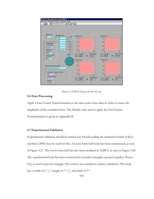
5.6 Data ProcessingFigure 5. 26 Wave Gage Labview Set-upApply a Fast Fourier Transformation to the time-series force data in order to assess theamplitude of the excitation force. The Matlab code used to apply the Fast FourierTransformation is given in Appendix B.5.7 Experimental ValidationExperimental validation should be carried out; Froude scaling the numerical model of Kooand Kim (2005) may be used for this. A Lewis form hull body has been constructed, as seenin Figure 5.27. The Lewis form hull has also been modeled in AQWA, as seen in Figure 5.28.The experimental body has been constructed of acrylic rectangles epoxied together. PermaOxy is used to prevent seepage. The corners are rounded to reduce turbulence. The bodyhas a width of 5 7 / 8 ”, length of 7 3 / 8 ”, and draft of 3”.104
Figure 5. 27 Experimental Lewis Form Hull BodyFigure 5. 28 Numerical Model of Lewis Form HullAgain no data have been collected. It is recommended for future students to carry out theexperimental validation before proceeding with the proposed experiment. Future studentsshould begin with the wave conditions given in Table 5.1.105
- Page 54 and 55: 221 2P gA C(77)max g2 3.8 Maximum
- Page 56 and 57: 4.2 AQWA Modeling ProcedureThe user
- Page 58 and 59: : Local data has changed, and the c
- Page 60 and 61: Figure 4. 5 Drawing in Design Modul
- Page 62 and 63: 12. Delete all lines inside the cur
- Page 64 and 65: 22. Edit the details of the slice u
- Page 66 and 67: Figure 4. 15 Details of the Part7.
- Page 68 and 69: Figure 4. 17 Details of the Mesh4.2
- Page 70 and 71: Figure 4. 21 Detials of the Wave Di
- Page 72 and 73: 5. Highlight Diffraction + Froude-K
- Page 74 and 75: Table 4.1 Body Dimensions for Numer
- Page 76 and 77: concavity from concave down to conc
- Page 78 and 79: Figure 4. 29 Maximum Power Absorpti
- Page 80 and 81: Table 4. 3 Numerical ResultsBodyNo.
- Page 82 and 83: BodyNo.Bodyλ atT=2.1λ atT=1.0λ a
- Page 84 and 85: WAVEFigure 5. 1 Body Faces Wave Mak
- Page 86 and 87: The body connects to the aluminum p
- Page 88 and 89: also allowed for flexibility in cre
- Page 90 and 91: AB1 23 4 5 6 7CD8 9 10 11EFigure 5.
- Page 92 and 93: and minimum voltage range of the DA
- Page 94 and 95: Figure 5. 11 Deleting a Step from L
- Page 96 and 97: Figure 5. 14 Recording Options, Sig
- Page 98 and 99: Figure 5. 17 Right-mouse Click on t
- Page 100 and 101: Zero-OffsetThe Zero-Offset step rem
- Page 102 and 103: Figure 5. 24 Filter Step Set-up, Co
- Page 106 and 107: 5.8 Experimental DiscussionAs menti
- Page 108 and 109: 5.8.3 Suggestions for Future Resear
- Page 110 and 111: 110ikxxRekddzkgkn )cosh())(cosh(,
- Page 112 and 113: Proof M ij and B ij are Symmetric T
- Page 114 and 115: BIBILIOGRAPHYANSYS. (n.d.). ANSYS A
- Page 116: Trust, C. (2011). Capital, Operatin
5.6 Data ProcessingFigure 5. 26 Wave Gage Labview Set-upApply a Fast Fourier Transformation to the time-series force data in order to assess theamplitude of the excitation force. The Matlab code used to apply the Fast FourierTransformation is given in Appendix B.5.7 Experimental ValidationExperimental validation should be carried out; Froude scaling the numerical model of Kooand Kim (2005) may be used for this. A Lewis form hull body has been constructed, as seenin Figure 5.27. The Lewis form hull has also been modeled in AQWA, as seen in Figure 5.28.The experimental body has been constructed of acrylic rectangles epoxied together. PermaOxy is used to prevent seepage. The corners are rounded to reduce turbulence. The bodyhas a width of 5 7 / 8 ”, length of 7 3 / 8 ”, and draft of 3”.104


