Quick Reference for End-Users Lambda Transmitter LT2 ... - lamtec
Quick Reference for End-Users Lambda Transmitter LT2 ... - lamtec Quick Reference for End-Users Lambda Transmitter LT2 ... - lamtec
4 Technical DescriptionMeasurement accuracy:Temperature - better than 2KEfficiency / exhaust gas losses - better than 0.2%Electric connections:depending on configuration / componentsMeasurement card:3 42221201926252423Y2 - PT 100measuring elementX2 - no connectIn the 657 R 0896 version, the intake air is specified as a constant. The intake air temperature is not measured. Only recommended where the intake temperatureremains nearly constant over the whole year.You can set the average temperature of the intake air in Parameter 1450.4.5.4 Calculation of CO2 ConcentrationCalculated by referring to the fuel from the measured O 2 value and the CO 2 maximumvalue type 657 R 0910The calculation follows the formula:CO 2 = CO 2 max – (21% -O 2 / 21%)The calculation is based on the following max. CO 2 -contents at = 1 O 2 = 0 Vol.% referenced to dry exhaust gas.Heating oilNatural gas Natural gasELHL15.4 Vol.%12.0 Vol.%11.7 Vol.%Individual specification of CO 2 max. is possible via the parameters 846, 862, 878 and 894.4.5.5 Load-dependent and Fuel-specific Limit Values/Limit CurvesThe burner firing-rate value or some other measured quantity is supplied via analogue input 4or via LAMTEC SYSTEM BUS. Instead of fixed limit values you can enter fuel-specific curveswith 2 up to a maximum of 8 checkpoints.25
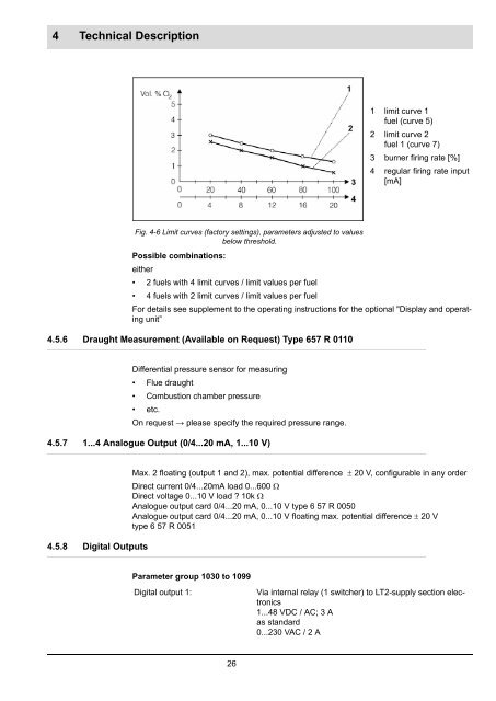
4 Technical Description1 limit curve 1 fuel (curve 5)2 limit curve 2fuel 1 (curve 7)3 burner firing rate [%]4 regular firing rate input[mA]Fig. 4-6 Limit curves (factory settings), parameters adjusted to valuesbelow threshold.Possible combinations:either• 2 fuels with 4 limit curves / limit values per fuel• 4 fuels with 2 limit curves / limit values per fuelFor details see supplement to the operating instructions for the optional "Display and operatingunit”4.5.6 Draught Measurement (Available on Request) Type 657 R 0110Differential pressure sensor for measuring• Flue draught• Combustion chamber pressure• etc.On request → please specify the required pressure range.4.5.7 1...4 Analogue Output (0/4...20 mA, 1...10 V)4.5.8 Digital OutputsMax. 2 floating (output 1 and 2), max. potential difference 20 V, configurable in any orderDirect current 0/4...20mA load 0...600 Direct voltage 0...10 V load ? 10k Analogue output card 0/4...20 mA, 0...10 V type 6 57 R 0050 Analogue output card 0/4...20 mA, 0...10 V floating max. potential difference 20 Vtype 6 57 R 0051Parameter group 1030 to 1099Digital output 1:Via internal relay (1 switcher) to LT2-supply section electronics1...48 VDC / AC; 3 Aas standard0...230 VAC / 2 A26
- Page 1: Quick Reference for End-UsersLambda
- Page 4 and 5: Table of Contents5.3 Wiring Example
- Page 6 and 7: 1 General Information1 General Info
- Page 8 and 9: 2 Safety2.2 For Your Safety2.2.1 Ex
- Page 10 and 11: 2 SafetyUser groupsTwo user groups
- Page 12 and 13: 3 Overview3 Overview3.1 System Over
- Page 14 and 15: 3 Overview3.2 Brief DescriptionUniv
- Page 16 and 17: 4 Technical Description10 LT2 Lambd
- Page 18 and 19: 4 Technical Description4.2.2 Probe
- Page 20 and 21: 4 Technical Description3: Displaya0
- Page 22 and 23: 4 Technical Description12: Analogue
- Page 24 and 25: 4 Technical Description4.5 Options4
- Page 28 and 29: 4 Technical DescriptionDigital outp
- Page 30 and 31: 5 LAMTEC SYSTEM BUS (LSB)5 LAMTEC S
- Page 32 and 33: 6 Commissioning / Shutdown6 Commiss
- Page 34 and 35: 6 Commissioning / Shutdown6.2.3 Int
- Page 36 and 37: 6 Commissioning / ShutdownNOTICE!Re
- Page 38 and 39: 7 Operation7 Operation7.1 Operation
- Page 40 and 41: 7 Operation7.2.3 Liquid Purificatio
- Page 42 and 43: 8 Service and MaintenanceCAUTION!Do
- Page 44 and 45: 9 Faults / Warnings9 Faults / Warni
- Page 46 and 47: 9 Faults / Warnings9.3.1 Faults - C
- Page 48 and 49: 9 Faults / Warnings9.4.2 Offset Vol
- Page 50 and 51: 11 Appendix11 Appendix11.1 Technica
- Page 52 and 53: 11 AppendixTechnical Data Lambda Tr
- Page 54 and 55: 11 Appendix11.3 Electric Connection
- Page 56 and 57: 11 Appendix11.4 Wet/Dry Measurement
- Page 58 and 59: 12 Declaration of Conformity12 Decl
- Page 60: 12 Declaration of Conformity59
4 Technical Description1 limit curve 1 fuel (curve 5)2 limit curve 2fuel 1 (curve 7)3 burner firing rate [%]4 regular firing rate input[mA]Fig. 4-6 Limit curves (factory settings), parameters adjusted to valuesbelow threshold.Possible combinations:either• 2 fuels with 4 limit curves / limit values per fuel• 4 fuels with 2 limit curves / limit values per fuelFor details see supplement to the operating instructions <strong>for</strong> the optional "Display and operatingunit”4.5.6 Draught Measurement (Available on Request) Type 657 R 0110Differential pressure sensor <strong>for</strong> measuring• Flue draught• Combustion chamber pressure• etc.On request → please specify the required pressure range.4.5.7 1...4 Analogue Output (0/4...20 mA, 1...10 V)4.5.8 Digital OutputsMax. 2 floating (output 1 and 2), max. potential difference 20 V, configurable in any orderDirect current 0/4...20mA load 0...600 Direct voltage 0...10 V load ? 10k Analogue output card 0/4...20 mA, 0...10 V type 6 57 R 0050 Analogue output card 0/4...20 mA, 0...10 V floating max. potential difference 20 Vtype 6 57 R 0051Parameter group 1030 to 1099Digital output 1:Via internal relay (1 switcher) to <strong>LT2</strong>-supply section electronics1...48 VDC / AC; 3 Aas standard0...230 VAC / 2 A26


