Quick Reference for End-Users Lambda Transmitter LT2 ... - lamtec
Quick Reference for End-Users Lambda Transmitter LT2 ... - lamtec
Quick Reference for End-Users Lambda Transmitter LT2 ... - lamtec
- No tags were found...

Create successful ePaper yourself
Turn your PDF publications into a flip-book with our unique Google optimized e-Paper software.
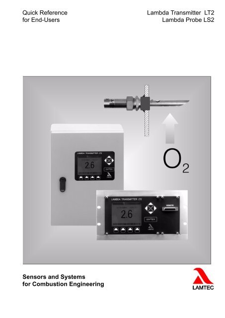
<strong>Quick</strong> <strong>Reference</strong> <strong>for</strong> <strong>End</strong>-<strong>Users</strong><strong>Lambda</strong> <strong>Transmitter</strong> <strong>LT2</strong><strong>Lambda</strong> Probe LS2Sensors and Systems <strong>for</strong> Combustion Engineering
Table of ContentsTable of Contents1 GENERAL INFORMATION . . . . . . . . . . . . . . . . . . . . . . . . . . . . . . . . . . . . . . . .51.1 Validity of these Instructions. . . . . . . . . . . . . . . . . . . . . . . . . . . . . . . . . . . . . . . . . . . . . . . . . . 52 SAFETY . . . . . . . . . . . . . . . . . . . . . . . . . . . . . . . . . . . . . . . . . . . . . . . . . . . . . . .62.1 German Law on Device Safety . . . . . . . . . . . . . . . . . . . . . . . . . . . . . . . . . . . . . . . . . . . . . . . . 62.2 For Your Safety . . . . . . . . . . . . . . . . . . . . . . . . . . . . . . . . . . . . . . . . . . . . . . . . . . . . . . . . . . . . . 72.2.1 Explanation of the Symbols in the Safety Notes. . . . . . . . . . . . . . . . . . . . . . . . . . . . . . . 72.2.2 Proper Use - Conditions of Use . . . . . . . . . . . . . . . . . . . . . . . . . . . . . . . . . . . . . . . . . . . 82.2.3 Authorised <strong>Users</strong> . . . . . . . . . . . . . . . . . . . . . . . . . . . . . . . . . . . . . . . . . . . . . . . . . . . . . .82.2.4 Safety Facilities / Safety Measures . . . . . . . . . . . . . . . . . . . . . . . . . . . . . . . . . . . . . . . . 92.2.5 Protection Against Emissions from Gas-carrying Channels . . . . . . . . . . . . . . . . . . . . . . 92.2.6 Important Notes on Shutdown/Return to Service . . . . . . . . . . . . . . . . . . . . . . . . . . . . . 102.2.7 Environmental Protection, Waste Disposal . . . . . . . . . . . . . . . . . . . . . . . . . . . . . . . . . 103 OVERVIEW . . . . . . . . . . . . . . . . . . . . . . . . . . . . . . . . . . . . . . . . . . . . . . . . . . .113.1 System Overview . . . . . . . . . . . . . . . . . . . . . . . . . . . . . . . . . . . . . . . . . . . . . . . . . . . . . . . . . . 113.2 Brief Description. . . . . . . . . . . . . . . . . . . . . . . . . . . . . . . . . . . . . . . . . . . . . . . . . . . . . . . . . . . 134 TECHNICAL DESCRIPTION. . . . . . . . . . . . . . . . . . . . . . . . . . . . . . . . . . . . . .144.1 System Overview - Necessary Components . . . . . . . . . . . . . . . . . . . . . . . . . . . . . . . . . . . . 144.1.1 Advantages of the Measurement Principle. . . . . . . . . . . . . . . . . . . . . . . . . . . . . . . . . . 154.2 <strong>LT2</strong> <strong>Lambda</strong> <strong>Transmitter</strong> . . . . . . . . . . . . . . . . . . . . . . . . . . . . . . . . . . . . . . . . . . . . . . . . . . . .164.2.1 <strong>LT2</strong> <strong>Lambda</strong> <strong>Transmitter</strong> in Wall Mounting Case . . . . . . . . . . . . . . . . . . . . . . . . . . . . . 164.2.2 Probe Connection Box (PCB). . . . . . . . . . . . . . . . . . . . . . . . . . . . . . . . . . . . . . . . . . . . 174.3 Cold-start Delay . . . . . . . . . . . . . . . . . . . . . . . . . . . . . . . . . . . . . . . . . . . . . . . . . . . . . . . . . . . 174.4 Device Configuration and Factory Setting . . . . . . . . . . . . . . . . . . . . . . . . . . . . . . . . . . . . . . 184.5 Options . . . . . . . . . . . . . . . . . . . . . . . . . . . . . . . . . . . . . . . . . . . . . . . . . . . . . . . . . . . . . . . . . . 234.5.1 Display and Operating Unit Type 657 R 0831 . . . . . . . . . . . . . . . . . . . . . . . . . . . . . . . 234.5.2 Remote-display-software . . . . . . . . . . . . . . . . . . . . . . . . . . . . . . . . . . . . . . . . . . . . . . . 244.5.3 Calculation of Combustion Efficiency Type 657 R 0895 / R 0896 . . . . . . . . . . . . . . . . 244.5.4 Calculation of CO2 Concentration . . . . . . . . . . . . . . . . . . . . . . . . . . . . . . . . . . . . . . . . 254.5.5 Load-dependent and Fuel-specific Limit Values/Limit Curves . . . . . . . . . . . . . . . . . . . 254.5.6 Draught Measurement (Available on Request) Type 657 R 0110 . . . . . . . . . . . . . . . . 264.5.7 1...4 Analogue Output (0/4...20 mA, 1...10 V) . . . . . . . . . . . . . . . . . . . . . . . . . . . . . . . 264.5.8 Digital Outputs . . . . . . . . . . . . . . . . . . . . . . . . . . . . . . . . . . . . . . . . . . . . . . . . . . . . . . . 264.5.9 1...4 Analogue Inputs . . . . . . . . . . . . . . . . . . . . . . . . . . . . . . . . . . . . . . . . . . . . . . . . . . 274.5.10 BUS interface . . . . . . . . . . . . . . . . . . . . . . . . . . . . . . . . . . . . . . . . . . . . . . . . . . . . . . . . 285 LAMTEC SYSTEM BUS (LSB) . . . . . . . . . . . . . . . . . . . . . . . . . . . . . . . . . . . .295.1 Jumpers, LED, Fuses and Terminals . . . . . . . . . . . . . . . . . . . . . . . . . . . . . . . . . . . . . . . . . . 295.2 Function. . . . . . . . . . . . . . . . . . . . . . . . . . . . . . . . . . . . . . . . . . . . . . . . . . . . . . . . . . . . . . . . . . 292
Table of Contents5.3 Wiring Example. . . . . . . . . . . . . . . . . . . . . . . . . . . . . . . . . . . . . . . . . . . . . . . . . . . . . . . . . . . . 306 COMMISSIONING / SHUTDOWN . . . . . . . . . . . . . . . . . . . . . . . . . . . . . . . . . .316.1 Factory Settings . . . . . . . . . . . . . . . . . . . . . . . . . . . . . . . . . . . . . . . . . . . . . . . . . . . . . . . . . . . 316.1.1 Device Configuration . . . . . . . . . . . . . . . . . . . . . . . . . . . . . . . . . . . . . . . . . . . . . . . . . . 316.2 Preliminary Works . . . . . . . . . . . . . . . . . . . . . . . . . . . . . . . . . . . . . . . . . . . . . . . . . . . . . . . . . 326.2.1 The <strong>LT2</strong> <strong>Lambda</strong> <strong>Transmitter</strong>'s Display and Operating Elements . . . . . . . . . . . . . . . . 326.2.2 Monitor Output . . . . . . . . . . . . . . . . . . . . . . . . . . . . . . . . . . . . . . . . . . . . . . . . . . . . . . .326.2.3 Internal Display and Operating Elements . . . . . . . . . . . . . . . . . . . . . . . . . . . . . . . . . . . 336.3 Measurement Start-up . . . . . . . . . . . . . . . . . . . . . . . . . . . . . . . . . . . . . . . . . . . . . . . . . . . . . . 346.3.1 Install the Probe in the PIF and Align the GED, See Illustration: . . . . . . . . . . . . . . . . . 356.4 Setting up Service Warnings . . . . . . . . . . . . . . . . . . . . . . . . . . . . . . . . . . . . . . . . . . . . . . . . . 366.5 Shutdown . . . . . . . . . . . . . . . . . . . . . . . . . . . . . . . . . . . . . . . . . . . . . . . . . . . . . . . . . . . . . . . . 367 OPERATION . . . . . . . . . . . . . . . . . . . . . . . . . . . . . . . . . . . . . . . . . . . . . . . . . .377.1 Operation / Measurement Value Display . . . . . . . . . . . . . . . . . . . . . . . . . . . . . . . . . . . . . . . 377.1.1 Measurement Value . . . . . . . . . . . . . . . . . . . . . . . . . . . . . . . . . . . . . . . . . . . . . . . . . . . 377.1.2 Commands . . . . . . . . . . . . . . . . . . . . . . . . . . . . . . . . . . . . . . . . . . . . . . . . . . . . . . . . . .377.1.3 Status Signals. . . . . . . . . . . . . . . . . . . . . . . . . . . . . . . . . . . . . . . . . . . . . . . . . . . . . . . . 387.1.4 Operating Parameters . . . . . . . . . . . . . . . . . . . . . . . . . . . . . . . . . . . . . . . . . . . . . . . . . 387.2 General Instructions <strong>for</strong> Operation . . . . . . . . . . . . . . . . . . . . . . . . . . . . . . . . . . . . . . . . . . . . 387.2.1 Measurement During Pronounced Pressure Surges at the Measuring Site. . . . . . . . . 387.2.2 Operational Failure, Switching On and Off . . . . . . . . . . . . . . . . . . . . . . . . . . . . . . . . . . 387.2.3 Liquid Purification . . . . . . . . . . . . . . . . . . . . . . . . . . . . . . . . . . . . . . . . . . . . . . . . . . . . .398 SERVICE AND MAINTENANCE . . . . . . . . . . . . . . . . . . . . . . . . . . . . . . . . . . .408.1 Checking the O2 Probe . . . . . . . . . . . . . . . . . . . . . . . . . . . . . . . . . . . . . . . . . . . . . . . . . . . . . 408.1.1 Checking the Air Voltage . . . . . . . . . . . . . . . . . . . . . . . . . . . . . . . . . . . . . . . . . . . . . . . 408.1.2 Checking by Counter-measurement. . . . . . . . . . . . . . . . . . . . . . . . . . . . . . . . . . . . . . . 418.2 Checking the <strong>LT2</strong> . . . . . . . . . . . . . . . . . . . . . . . . . . . . . . . . . . . . . . . . . . . . . . . . . . . . . . . . . . 428.2.1 Checking the <strong>LT2</strong>'s Measuring Input . . . . . . . . . . . . . . . . . . . . . . . . . . . . . . . . . . . . . . 428.2.2 Checking the Probe's Internal Resistance Measurement. . . . . . . . . . . . . . . . . . . . . . . 428.3 Servicing . . . . . . . . . . . . . . . . . . . . . . . . . . . . . . . . . . . . . . . . . . . . . . . . . . . . . . . . . . . . . . . . . 428.3.1 Consumable . . . . . . . . . . . . . . . . . . . . . . . . . . . . . . . . . . . . . . . . . . . . . . . . . . . . . . . . .429 FAULTS / WARNINGS . . . . . . . . . . . . . . . . . . . . . . . . . . . . . . . . . . . . . . . . . .439.1 Faults . . . . . . . . . . . . . . . . . . . . . . . . . . . . . . . . . . . . . . . . . . . . . . . . . . . . . . . . . . . . . . . . . . . . 439.2 Warnings . . . . . . . . . . . . . . . . . . . . . . . . . . . . . . . . . . . . . . . . . . . . . . . . . . . . . . . . . . . . . . . . . 439.3 Resetting Faults / Warnings . . . . . . . . . . . . . . . . . . . . . . . . . . . . . . . . . . . . . . . . . . . . . . . . .449.3.1 Faults - Causes and Solutions . . . . . . . . . . . . . . . . . . . . . . . . . . . . . . . . . . . . . . . . . . . 459.4 Warnings - Causes and Solutions. . . . . . . . . . . . . . . . . . . . . . . . . . . . . . . . . . . . . . . . . . . . . 463
Table of Contents9.4.1 LS2 Internal Resistance too High . . . . . . . . . . . . . . . . . . . . . . . . . . . . . . . . . . . . . . . . . 469.4.2 Offset Voltage to Air Invalid . . . . . . . . . . . . . . . . . . . . . . . . . . . . . . . . . . . . . . . . . . . . . 479.4.3 Analogue Inputs 1 / 2 / 3 / 4 Input Value too Large/too Small . . . . . . . . . . . . . . . . . . . 479.4.4 Configuration Error at Analogue Outputs . . . . . . . . . . . . . . . . . . . . . . . . . . . . . . . . . . . 479.4.5 Service Warning 1 / Service Warning 2 . . . . . . . . . . . . . . . . . . . . . . . . . . . . . . . . . . . . 4710 SPARE PARTS . . . . . . . . . . . . . . . . . . . . . . . . . . . . . . . . . . . . . . . . . . . . . . . .4811 APPENDIX. . . . . . . . . . . . . . . . . . . . . . . . . . . . . . . . . . . . . . . . . . . . . . . . . . . .4911.1 Technical data <strong>LT2</strong> <strong>Lambda</strong> <strong>Transmitter</strong> . . . . . . . . . . . . . . . . . . . . . . . . . . . . . . . . . . . . . . . 4911.2 Technical Data LS2 <strong>Lambda</strong> Probe. . . . . . . . . . . . . . . . . . . . . . . . . . . . . . . . . . . . . . . . . . . . 5111.3 Electric Connections Device Side. . . . . . . . . . . . . . . . . . . . . . . . . . . . . . . . . . . . . . . . . . . . . 5311.3.1 Jumpers . . . . . . . . . . . . . . . . . . . . . . . . . . . . . . . . . . . . . . . . . . . . . . . . . . . . . . . . . . . . 5311.3.2 DIP Switch . . . . . . . . . . . . . . . . . . . . . . . . . . . . . . . . . . . . . . . . . . . . . . . . . . . . . . . . . . 5311.3.3 Fuses . . . . . . . . . . . . . . . . . . . . . . . . . . . . . . . . . . . . . . . . . . . . . . . . . . . . . . . . . . . . . . 5311.3.4 <strong>LT2</strong> Power Electronic Type 657 R 1882. . . . . . . . . . . . . . . . . . . . . . . . . . . . . . . . . . . . 5411.4 Wet/Dry Measurement Deviations, Conversion Table. . . . . . . . . . . . . . . . . . . . . . . . . . . . . 5512 DECLARATION OF CONFORMITY . . . . . . . . . . . . . . . . . . . . . . . . . . . . . . . .574
1 General In<strong>for</strong>mation1 General In<strong>for</strong>mation1.1 Validity of these InstructionsWhat does these operating instruction describe?These operating instructions describe the <strong>LT2</strong> <strong>Lambda</strong> transmitter with all the componentsnecessary <strong>for</strong> O 2 measurements such as the LS2 <strong>Lambda</strong> probe, probe installation fitting etc.Accessories and special applicationsThe accompanying documentation applies to accessories and special applications. If necessary,please contact the Walldorf works <strong>for</strong> any in<strong>for</strong>mation required.These operating instructions serve to understand the <strong>LT2</strong> <strong>Lambda</strong> transmitter's functions, assembly,installation and maintenance works and its operation. Other documentation, such ase.g. product data sheets, may contain further in<strong>for</strong>mation but should never be used as a substitute<strong>for</strong> these instructions.CAUTION!Always read the operating instructions be<strong>for</strong>e starting work! Carefully observe all warningnotes!Certain works, such as electric installation, presuppose special expertise. These works mayonly be carried out by personnel with the appropriate qualifications. See the chapter 2.2.3 Authorised<strong>Users</strong>.ValidityOur products undergo constant development. Equally, we make every ef<strong>for</strong>t to ensure that theoperating instructions are accurate and customised <strong>for</strong> the individual application.Previous editions become void as soon as a supplemented and amended new edition is issued.On the last page you will find the current version number of these operating instructions andthe associated ordering number.5
2 Safety2 Safety2.1 German Law on Device SafetyThe German Law on Device Safety regulates the following:Note the instructions <strong>for</strong> use!Use the device only in compliance with the instructions, which are contained in this document<strong>for</strong> <strong>LT2</strong> (publication no. DLT6080-10-aEN-034).If this document is a supplement, use it only in combination with the basic manuals.Use the devices only <strong>for</strong> the purpose described in this documentation.Used by trained personnel only.Only persons whose knowledge and training qualifies them to do so, are allowed to operateand service the device . Note the safety provisions of the burner manufacturer.To be used only in a grounded power line network!Electrical connection with devices that are not mentioned in this operating instructions- only after consultation with the manufactorers or an authorized expert.Liability <strong>for</strong> the function of the device shall be transferred to the owner or user.Liability <strong>for</strong> the function of the device shall be borne by the owner or user insofar as the devicehas been used by persons without the necessary knowledge, has been improperly used, servicedor repaired or has been handled in a manner that does not con<strong>for</strong>m to proper use.Modifications to the device render the type approval null and void. Inputs and outputs of thedevice and associated modules may only be connected as indicated in this manual.LAMTEC GmbH & Co. KG is not liable <strong>for</strong> damages occurring as a result of non-compliancewith the above instructions. Compliance with the above instructions shall not entail any extensionto the warranty and liability provisions of LAMTEC GmbH & Co. KG's terms of saleand delivery.Insofar as reference is made to laws, regulations and standards, the basis <strong>for</strong> these shall bethe law of the Federal Republic of Germany.6
2 Safety2.2 For Your Safety2.2.1 Explanation of the Symbols in the Safety NotesThe following symbols are used in these operating instructions as important safety notes <strong>for</strong>the user. They appear within each chapter where the in<strong>for</strong>mation is required. The safety notes,in particular the warnings, must always be observed and followed.DANGER!Identifies possible hazards to personnel, especially through electric power.WARNING!Indicates possible hazards to personnel caused by improper handling of system parts.CAUTION!Indicates risk to system parts or a possible adverse effect on functions.NOTICE!Contains important additional in<strong>for</strong>mation <strong>for</strong> the user about the system or system parts, andoffers further tips.Appears in texts containing instructions <strong>for</strong> carrying out an action.In this context the user is urged to observe the statutory accident prevention measures duringall works, and to do everything in accordance with the situation to prevent damage to personsand property.7
2 Safety2.2.2 Proper Use - Conditions of Use2.2.3 Authorised <strong>Users</strong>ApplicationThe <strong>LT2</strong> <strong>Lambda</strong> transmitter is an O 2 measuring instrument <strong>for</strong> the continuous measurementof O 2 concentration in non-combustible gases in the super-stoichiometric domain, in conjunctionwith the <strong>LT2</strong> <strong>Lambda</strong> probe.If the system is to be used in some other way, and if the instrument's functionality in this applicationcannot be unambiguously assessed, the manufacturer should be contacted in advance.PrerequisitesIt is assumed that facility planning, assembly, installation, commissioning, maintenance andservice works are carried out by sufficiently trained personnel, and these works are supervisedby qualified specialists.Correct handlingSpecial attention must be paid to the following:– The application must con<strong>for</strong>m to the technical data and the specifications regarding authoriseduse, assembly, connection, environmental and operational conditions (derivedfrom the job documentation, the instrument's user in<strong>for</strong>mation, rating plates etc), and tothe documentation supplied.– The local regulations and facility-specific and technical hazards must be noted and followed.– All steps necessary to protect the equipment, e.g. during transport, storage, maintenanceand inspection, should be carried out.Qualified personnelThose responsible <strong>for</strong> safety must always ensure that– only qualified personnel carry out work on system parts. Qualified personnel have been authorised by those responsible <strong>for</strong> maintaining the safetyof employees and that of the facility, to per<strong>for</strong>m such activities as a result of their training,experience or familiarity with the relevant Standards, regulations, accident preventionmeasures and local conditions. The important factor is that such personnel are able toidentify and prevent possible hazards in good time.Specialist personnel are those meeting DIN VDE 0105 or IEC 364, or directly comparableStandards such as DIN 0832.– these personnel have the supplied operating instructions and the associated, job-relateddocumentation available to them during all works, and observe these documents in orderto avoid hazards and damage.8
2 SafetyUser groupsTwo user groups are assumed to handle the <strong>LT2</strong> <strong>Lambda</strong> transmitter:a Operators, the customer's installers, measurement/control/electric/electronic technicians- have elementary knowledge of the instrument.b Service technicians of LAMTEC or their OEM customers, or the customer's trained personnel:qualified technicians/engineers - have very good knowledge of the instrument.c Operating personnel with basic knowledge access level "OPERATION SERVICE" - without password2.2.4 Safety Facilities / Safety MeasuresHazards from electric equipmentThe <strong>LT2</strong>’s system parts are items of equipment designed to be used in industrial high-currentfacilities. When working on parts connected to the supply or carrying supply voltage, disconnectfrom the supply and ensure zero voltage. Re-install all machine guards be<strong>for</strong>e reconnectingto the supply.Damage to health or to property may result from improper use or incorrect handling. To preventdamage, observe the appropriate safety notes.Preventive measures <strong>for</strong> improving operating safetyWhere the <strong>LT2</strong> is used as a sensor in conjunction with regulating or control systems, it is theoperator's responsibility to ensure that <strong>LT2</strong> failure or faults cannot lead to dangerous situationsor those that cause unacceptable damage.In order to prevent faults, which in turn could cause direct or indirect damage to personnel orto property, the operator must ensure that– the appointed maintenance personnel can be notified at any time and as soon as possible,the maintenance personnel are trained to respond correctly to <strong>LT2</strong> faults and associatedoperational faults– in the event of doubt, the affected equipment is immediately switched off– switching off does not lead to direct consequential faultsCAUTION!In risk of a shortfall below the dew point in the gas channel, you must heat the gas extractiondevice (MEV) and eventually the preliminary filter electrically.Prevention of consequential damageTo prevent consequential damage in the event of instrument faults, which in turn could causedirect or indirect damage to personnel or property, ensure that qualified personnel assess thefaults and initiate appropriate steps.2.2.5 Protection Against Emissions from Gas-carrying ChannelsThe <strong>LT2</strong> <strong>Lambda</strong> transmitter is directly attached to the gas-carrying channel, via the probe installationfitting (SEA). If the <strong>LT2</strong> <strong>Lambda</strong> probe or the SEA installation fitting are dismantled;then depending on the facility and particularly in the event of excess pressure, aggressive and/or hot gas may be emitted from the channel and cause severe health damage to unprotectedoperatives, unless suitable protective measures have previously been put into place.9
2 SafetyWARNING!In the event of excess pressure and temperatures above 200°C in the gas channel, dismantlingthe <strong>LT2</strong> <strong>Lambda</strong> probe or the installation fitting lead to the emission of gases.- Switch off the facility be<strong>for</strong>e opening. If this is not possible, wear protective clothing and aprotective mask.- Put up appropriate warning signs near the installation site.- Close the aperture at once. You can get adequate sealing flanges, (blind flang) as an accessory.2.2.6 Important Notes on Shutdown/Return to ServiceThe <strong>LT2</strong> <strong>Lambda</strong> transmitter and the LS2 <strong>Lambda</strong> probe <strong>for</strong>m a high quality electronic measurementsystem. Treat them with care at all times, including during shutdown, transport andstorage.ShutdownCAUTION!Do not switch the <strong>LT2</strong> <strong>Lambda</strong> transmitter off as long as the LS2 <strong>Lambda</strong> probe is mounted;including when the relevant facility has been shut down. Residual gases cause corrosion andmay damage system parts.Do not store the instruments outdoors without protection!Always store in a dry place, if possible in the original packaging.When dismantling, protect cable ends and plugs against corrosion and dirt. Corroded plugsmay cause malfunction.If possible, transport in the original packaging.Return to serviceAccording to chapter 6 Commissioning / Shutdown.2.2.7 Environmental Protection, Waste DisposalThe <strong>LT2</strong> <strong>Lambda</strong> transmitter's construction is also based on environmental considerations.The modules can easily be separated and sorted into distinct types, and recycled accordingly.10
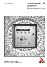
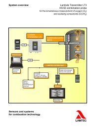
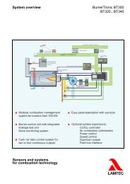
3 Overview3 Overview3.1 System OverviewThe <strong>LT2</strong> <strong>Lambda</strong> <strong>Transmitter</strong> is a universal, microprocessor-based measuring device <strong>for</strong> directlymeasuring the O 2 concentration in the super-stoichiometric range (λ > 1) in combinationwith the proven <strong>Lambda</strong> probe LS2.The Combination Probe KS 1 can be connected <strong>for</strong> measuring combustible gas constituents(CO/H 2 ).Fig. 3-1 System overview <strong>LT2</strong> <strong>Lambda</strong> <strong>Transmitter</strong>11
3 OverviewFig. 3-2 System overview - <strong>LT2</strong> <strong>Lambda</strong> <strong>Transmitter</strong> input / output modules12
3 Overview3.2 Brief DescriptionUniversal O 2 measuring instrument, based on the LS2 <strong>Lambda</strong> probe (zirconium dioxide voltageprobe), <strong>for</strong> the direct continuous measurement and monitoring of oil (EL) and gas combustionsystems in the super-stoichiometric domain ( > 1)without special gas purification.Fig. 3-3 <strong>LT2</strong> <strong>Lambda</strong> <strong>Transmitter</strong> wall-mounting housing IP 65400 x 300 x 150 mm (H x B x T) type 657 R 1025Fig. 3-4 <strong>LT2</strong> <strong>Lambda</strong> <strong>Transmitter</strong> on mounting plate173 x 310 x 270 mm (H x B x T) type 657 R 1030Fig. 3-5 <strong>Lambda</strong> <strong>Transmitter</strong> <strong>LT2</strong> panel installation 3HE, 50HE173 x 310 x 270 mm (H x B x T) type 657 R 1040Fig. 3-6 <strong>Lambda</strong> Sonde LS2,Type 650 R 1000 with gas extraction device (MEV) type 655 R1001 - R 1003 andprobe installation fitting (PIF) type 655 R 101013
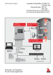
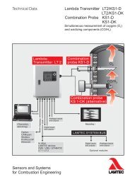
4 Technical Description4 Technical Description4.1 System Overview - Necessary ComponentsThe O 2 measurement system is available in various versions.It consists of the following components:– <strong>LT2</strong> <strong>Lambda</strong> probe– Gas extraction device (GED)– Probe installation fitting (PIF)– Probe connection box (PCB)– <strong>LT2</strong> <strong>Lambda</strong> <strong>Transmitter</strong> in IP 54 wall-mounted housingalternatively - on mounting plate- panel installation housing including display and operating unitM measuring gas 300°C max.1 plug2 probe signal3 <strong>Lambda</strong> Probe LS2, Type 6 50 R 10004 gas extraction device (GED)5 half-collar R11/4“, type 6 55 R 10126 probe installation fitting (PIF), Type 6 55 R 10107 probe heater8 probe connection box (PCB), Type 6 55 R 1025 (optional)9 display and operating unit, Type 6 57 R 083114
4 Technical Description10 <strong>LT2</strong> <strong>Lambda</strong> <strong>Transmitter</strong> panel installation3 HE, 50 TE 173 x 310 x 280 mm (h x w x d)type 657 R 104011 <strong>LT2</strong> <strong>Lambda</strong> <strong>Transmitter</strong> in IP 54 wall-mounted housing type 657 R 1025,sheet steel, 400 x 300 x 150 mm (h x w x d) with display and operating unit13 <strong>LT2</strong> <strong>Lambda</strong> <strong>Transmitter</strong> on mounting plate350x258x132 (HxBxT) type 657 R 10304.1.1 Advantages of the Measurement Principle• No gas treatment needed, measurement directly in the humid flue gas• Setting time at 90%-value (T 90 ) < 20 seconds• measuring gas temperature up to 300 °C• low heating power 15...25 Wattdepending on the state of aging of the zirconium dioxid sensor• universal applycable• easy application• low-maintenance15
4 Technical Description4.2 <strong>LT2</strong> <strong>Lambda</strong> <strong>Transmitter</strong>4.2.1 <strong>LT2</strong> <strong>Lambda</strong> <strong>Transmitter</strong> in Wall Mounting Case1 Display and operating unit2 Probe and electronics trans<strong>for</strong>mer3 Connection <strong>for</strong> Remote-Display-Software (Option)4 Connecting cable with plug <strong>for</strong> display and operating unit5 Electrical connections6 BUS-interface alternative LAMTEC SYSTEM BUS (CAN BUS)7 Operating mode display multifunction push button maintenance switch8 Protective earth terminal <strong>for</strong> cable screening9 Monitor output10 Mains connection (plug)11 Terminal bar x 212 Relay module type 660 R 0017Fig. 4-1 <strong>LT2</strong> <strong>Lambda</strong> <strong>Transmitter</strong> in wall-mounting housing type 657 R 1025 with displayand operating unit type 657 R 0831Accessible after removing the front panel with the mainswitch ("POWER”)Fig. 4-2 Change over power supply voltage16
4 Technical Description4.2.2 Probe Connection Box (PCB)For use at large distances between probe and analyser, where no customised cable is employed.Input: Probe plugOutput: Terminal stripThe PCB contains a terminal strip and conversion to the probe and heating plugs.Fig. 4-3 PCB-Dimension diagram high: 40 mm protection class: IP55Fig. 4-4 PCB-Connection diagram33 Probe signal -34 Probe signal +35 Probe heater 13V DC36 Probe heater 13V DCNOTICE!Keep the distance to the PCB as short as possible. Avoid distances of more than 450 mm ifpossible.4.3 Cold-start DelayServes to suppress false measurements while the probe warms up to operating temperature.Cold-start delay is always activated after "Power off” and probe replacement.The cold-start delay can be aborted at any time• via the multifunction key• via the optional display and operating unit, see separate publication• via Remote-Display-Software, see separate publicationDuring the cold-start delay, either• a substitute value (factory setting), O 2 0 Vol.% (P361)• You can set the type of the substitute value <strong>for</strong> O 2 in P362:OFF: No output of the substitute valueON: Output of the substitute value of the preceding parameter.17
4 Technical Description+Maintenance: (factory setting): Output of the substitute value of the preceding parameter,even in maintenance mode.+Maint.freeze: Output of the substitute value of the preceding parameter in the case of coldstart or error as hitherto. Additionally the preceding measurement value is freezed, as long asmaintenance mode is active.The substitute value during cold start/error takes priority over the freezing of the measurementvalue during maintenance.frozenAfter a pre-heating period of 10 minutes the probe voltage stabilises to a value between0...20mV and the AC inner resistance to a value below 100 .4.4 Device Configuration and Factory SettingYou can derive the device's variant from the variant number. You will find the variant numberon the type plate. The variant number is constructed according to the following key:Serial NumberExample: <strong>LT2</strong> in variant No.: LS2 1S a1 b0 c11 c21 c31 c40 d15 d25 d30 d40 e00 f4 g1 i0 k0 m1 n0 oE z0<strong>LT2</strong>: LS2 1S a1 b0 c11 c21 c31 c40 d15 d25 d30 d40 e00 f4 g1 i0 k0 m1 n0 oE z01 2 3 4 5 6 7 8 9 10 11 12 13 14 15 16 17 18 19 20 211: For probeKS1 configurated <strong>for</strong> CO-probe KS1KS1D configurated <strong>for</strong> Combination probe KS1DLS2 configurated <strong>for</strong> <strong>Lambda</strong> probe LS22: Type1S Standard type2OEM OEM type3a For probe with bypass and purge unit3K For probe type "K - semi automatic calibration"4KA For probe type "KA - semi automatic calibration and purge"5KV For probe type "KV - full automatic calibration"6KVA For probe type "KVA - full automatic calibration and purge"6KVZ For probe type "KV-full automatic calibration and regeneration cyclic"7EX1 For probe type "EX-area 1"8EX2 For probe type "EX-area 2"9E For probe type "HT - ejector extraction"18
4 Technical Description3: Displaya0 withouta1 with Display and operating unit 657R0831/33a2 with Display and operating unit 657R0833RBT4: Pressure sensorb1 with absolute pressure and differential pressureb2 with differential pressure sensorb3 with pressure sensor <strong>for</strong> draught measurement5: Analogue output 1c11 Analogue output 1 currrent 4...20mA 657R0050c12 Analogue output 1 currrent 0...20mA 657R0050c13 Analogue output 1 voltage 0...10V 657R0050c14 Analogue output 1 currrent 4...20mA floating 657R0054c15 Analogue output 1 currrent 4...20mA floating 657R0054REGc16 Analogue output 1 currrent 0...20mA floating 657R0054c17 Analogue output 1 voltage 0...10V floating 657R0054c18 Analogue output 1 ejector control 657R0050Ec19 Analogue output 1 currrent 4...20mA electrically isolated 657R00536: Analogue output 2c21 Analogue output 2 currrent 4...20mA 657R0050c22 Analogue output 2 currrent 0...20mA 657R0050c23 Analogue output 2 voltage 0...10V 657R0050c24 Analogue output 2 currrent 4...20mA floating 657R0051c25 Analogue output 2 currrent 4...20mA floating 657R0051REGc26 Analogue output 2 currrent 0...20mA floating 657R0051c27 Analogue output 2 voltage 0...10V floating 657R0051c28 Analogue output 2 ejector control 657R0050Ec29 Analogue output 2 currrent 4...20mA electrically isolated 657R00537: Analogue output 3c31 Analogue output 3 currrent 4...20mA 657R0050c32 Analogue output 3 currrent 0...20mA 657R0050c33 Analogue output 3 voltage 0...10V 657R0050c34 Analogue output 3 currrent 4...20mA floating 657R0051c35 Analogue output 3 currrent 4...20mA floating 657R0051REGc36 Analogue output 3 currrent 0...20mA floating 657R0051c37 Analogue output 3 voltage 0...10V floating 657R0051c38 Analogue output 3 ejector control 657R0050Ec39 Analogue output 3 currrent 4...20mA electrically isolated 657R005319
4 Technical Description8: Analogue output 4c41 Analogue output 4 currrent 4...20mA 657R0050c42 Analogue output 4 currrent 0...20mA 657R0050c43 Analogue output 4 voltage 0...10V 657R0050c44 Analogue output 4 currrent 4...20mA floating 657R0051c45 Analogue output 4 currrent 4...20mA floating 657R0051REGc46 Analogue output 4 currrent 0...20mA floating 657R0051c47 Analogue output 4 voltage 0...10V floating 657R0051c48 Analogue output 4 ejector control 657R0050Ec49 Analogue output 4 currrent 4...20mA electrically isolated 657R00539: Analogue input 1d11 Analogue input 1 potentiometer 1...5 kOHMd12 Analogue input 1 currrent 0/4...20mA passived13 Analogue input 1 voltage 0...2900mV (EX1)d14 Analogue input 1 pulse (RPM)d15 Analogue input 1 temperature PT100 0...320°Cd16 Analogue input 1 temperature PT100 0...850°Cd17 Analogue input 1 currrent 0/4...20mA active (24V supply)d18 Analogue input 1 differential pressured19 Analogue input 1 voltage -100...2000mV (KS1-D)10: Analogue input 2d21 Analogue input 2 potentiometer 1...5 kOHMd22 Analogue input 2 currrent 0/4...20mA passived23 Analogue input 2 voltage 0...2900 mV (EX1)d24 Analogue input 2 pulse (RPM)d25 Analogue input 2 temperature PT100 0...320°Cd26 Analogue input 2 temperature PT100 0...850°Cd27 Analogue input 2 currrent 0/4...20mA active (24V supply)d28 Analogue input 2 absolute pressured29 Analogue input 2 voltage 0...10V11: Analogue input 3d31 Analogue input 3 potentiometer 1...5 kOHMd32 Analogue input 3 current 0/4...20mA passived33 Analogue input 3 voltage 0...2900mV EX1d34 Analogue input 3 pulse (RPM)d35 Analogue input 3 temperature PT100 0...320°Cd36 Analogue input 3 temperature PT100 0...850°Cd37 Analogue input 3 current 0/4...20mA active (24V supply)d38 Analogue input 3 differential pressured39 Analogue input 3 voltage 0...10V20
4 Technical Description12: Analogue input 4d41 Analogue input 4 potentiometer 1...5 kOHMd42 Analogue input 4 current 0/4...20 mA passived43 Analogue input 4 voltage 0...2900mV EX1d44 Analogue input 4 pulse (RPM)d45 Analogue input 4 temperature PT100 0...320°Cd46 Analogue input 4 temperature PT100 0...850°Cd47 Analogue input 4current 0/4...20mA Active (24V supply)d48 Analogue input 4 absolute pressured49 Analogue input 4 voltage 0...10V13: RM/LI/Controller/Loade30 Relay module 657R0857e31 Load dep. limit values, load def. LSB and relay module 657R0922e32 Load dep. limit values, load def. poti and relay module 657R0922/POe33 Load dep. limit values, load def. current. and relay module 657R0922/STe34 O 2 -controller (PID), load def. LSB and relay module 657R1120e35 O 2 -controller PID, load def. poti and relay module 657R1120/POe36 O 2 -controllerr PID, load def. current. and relay module 657R1120/STe37 Speed depended O 2 -controller, load def. LSB and relay module 657R1123e38 Speed depended O 2 -controller, load def. LSB and relay module 657R1123/POe39 Speed depended O 2 -controller, load def. current and relay module657R1123/STe40 Output of "burner-firing rate" at analogue output 657R112414: Efficiency calculationf1 Efficiency calculation (fixed ambient temperature) 657R0896f2 Efficiency calculation 657R0895f3 Temperature measurement 0...320°/ 850°Cf4 Efficiency calculation incl. 2x PT100-sensors and analogue output657R0917f5 Efficiency calculation incl. 2x PT100-sensors 699R0895f6 Efficiency calculation incl. 1x PT100-sensors 699R089615: Supply voltageg1 Supply voltage 230VACg2 Supply voltage 115VAC16: <strong>Reference</strong> air pumpi1 Pump unit <strong>for</strong> reference air 230VAC 657R1060i3 Pump unit <strong>for</strong> reference air 115VAC 657R106017: Case heatingk1 Housing heating 230VAC / 120W 657R036721
4 Technical Description18: CO-monitoring/controllingm1 CO-controller master 657R0602m2 CO-controller slave 657R0602 & 663R1030m3 CO-monitoring master 657R0601m4 CO-monitoring slave 657R060119: Calculationsn1 CO 2 -calculation 657R0910n2 O 2 wet/dry-conversion 657R091820: LanguageoD Language German/EnglishoDF Language German/FrenchoE Language English/GermanoEF Language English/FrenchoFE Language French/English21: Special configurationz1 Special configuration 657R1030KS1D RBTz2 Special configuration analogue input 1-current 0-20mA analogue input 2-voltage 0-10Vz3 Special configuration stainless steel housing <strong>LT2</strong> without windowz4 Special configuration stainless steel housing <strong>LT2</strong> viewing doorz5 Special configuration stainless steel housing <strong>LT2</strong>K with windowz6 Special configuration assembling in EEX-housing 657R0165z7 Special configuration Load analogy via analogue input 1 and analogueinput 2 - limit value 1z8 Configuration by order22
4 Technical Description4.5 Options4.5.1 Display and Operating Unit Type 657 R 0831Fig. 4-5 Optional with <strong>LT2</strong> in wall-mounting housing type 657 R 1025optional with mounting plate type 657 R 1030at <strong>LT2</strong> type 657 R 1040 included as a standard <strong>for</strong> panel installationsee separate publication DLT 606023
4 Technical Description4.5.2 Remote-display-softwarePC-software to configure the <strong>LT2</strong>. Use it instead of the display and operating unit, and to storeand restore the data set.Remote-Display-Software including interface module RS 232 <strong>for</strong> PC type 657 R 1101Other licences <strong>for</strong> the remote-display-software type 657 R 1102For windows-based computers, connection with <strong>LT2</strong> via RS 232 interface.Refer to special documentation DLT1004.Suitable <strong>for</strong> all PCs with RS 232 or RS 422 interface from Windows 95, Windows NT (32-bitversion) onwardFor details see separate publication DLT 10044.5.3 Calculation of Combustion Efficiency Type 657 R 0895 / R 0896The calculation follows the <strong>for</strong>mula:n F = 100 (q Af + q Ag )%q Af = Exhaust gas loss through free heatq Ag = Exhaust gas loss through bounded heatq Af = (t A - t L ) * [A 2 /21 - O 2 + B]Calculation of exhaust gas losses is based on the following mean fuel values:OilGasA 2 = 0.68;A 2 = 0.66;It is assumed that the combustion is CO- and soot-free.Exhaust gas losses through bound heat are not taken into account.Display:EfficiencyExhaust gas lossesExhaust gas temperatureIntake air temperatureOther ranges on requestB = 0.007B = 0.0090...100%0...100%0...320°C0...320°C24
4 Technical DescriptionMeasurement accuracy:Temperature - better than 2KEfficiency / exhaust gas losses - better than 0.2%Electric connections:depending on configuration / componentsMeasurement card:3 42221201926252423Y2 - PT 100measuring elementX2 - no connectIn the 657 R 0896 version, the intake air is specified as a constant. The intake air temperature is not measured. Only recommended where the intake temperatureremains nearly constant over the whole year.You can set the average temperature of the intake air in Parameter 1450.4.5.4 Calculation of CO2 ConcentrationCalculated by referring to the fuel from the measured O 2 value and the CO 2 maximumvalue type 657 R 0910The calculation follows the <strong>for</strong>mula:CO 2 = CO 2 max – (21% -O 2 / 21%)The calculation is based on the following max. CO 2 -contents at = 1 O 2 = 0 Vol.% referenced to dry exhaust gas.Heating oilNatural gas Natural gasELHL15.4 Vol.%12.0 Vol.%11.7 Vol.%Individual specification of CO 2 max. is possible via the parameters 846, 862, 878 and 894.4.5.5 Load-dependent and Fuel-specific Limit Values/Limit CurvesThe burner firing-rate value or some other measured quantity is supplied via analogue input 4or via LAMTEC SYSTEM BUS. Instead of fixed limit values you can enter fuel-specific curveswith 2 up to a maximum of 8 checkpoints.25
4 Technical Description1 limit curve 1 fuel (curve 5)2 limit curve 2fuel 1 (curve 7)3 burner firing rate [%]4 regular firing rate input[mA]Fig. 4-6 Limit curves (factory settings), parameters adjusted to valuesbelow threshold.Possible combinations:either• 2 fuels with 4 limit curves / limit values per fuel• 4 fuels with 2 limit curves / limit values per fuelFor details see supplement to the operating instructions <strong>for</strong> the optional "Display and operatingunit”4.5.6 Draught Measurement (Available on Request) Type 657 R 0110Differential pressure sensor <strong>for</strong> measuring• Flue draught• Combustion chamber pressure• etc.On request → please specify the required pressure range.4.5.7 1...4 Analogue Output (0/4...20 mA, 1...10 V)4.5.8 Digital OutputsMax. 2 floating (output 1 and 2), max. potential difference 20 V, configurable in any orderDirect current 0/4...20mA load 0...600 Direct voltage 0...10 V load ? 10k Analogue output card 0/4...20 mA, 0...10 V type 6 57 R 0050 Analogue output card 0/4...20 mA, 0...10 V floating max. potential difference 20 Vtype 6 57 R 0051Parameter group 1030 to 1099Digital output 1:Via internal relay (1 switcher) to <strong>LT2</strong>-supply section electronics1...48 VDC / AC; 3 Aas standard0...230 VAC / 2 A26
4 Technical DescriptionDigital output 2 to 7:type 660 R 0857 (optional)Via internal relay module6 relays (1 switcher), switching capability max. 230 VAC, 4 Aalternative (on request)The outputs can be configured arbitrarily via the (optional) display and operating unit and theRemote-Display-Software. (parameter 1030...1099)4.5.9 1...4 Analogue InputsFig. 4-7 Relay module type 657 R 0857• analogue inputs via measurement cards, arbitrary configuration e.g. <strong>for</strong> temperature sensor,further pressure sensors, KS 1 combined probe, standard signals etc; max. 2 of thesefloating, max. potential difference 20 VExternal communication processor with PROFIBUS-moduleVia plug-in cart on <strong>LT2</strong>-power pack electronic (max. 2)• Analogue input card 0/4...20 mAtype 6 63 P 6001• Analogue input card 0/4...20 mAwith supply 24 VDC <strong>for</strong> transmitter LT1/<strong>LT2</strong>type 663 P 6002• Analogue input card <strong>for</strong> potentiometer1...5 ktype 657 P 6000• Input temperature <strong>for</strong> PT 100range of measuring alternative0...320 °C0...850 °C (please specify when ordering)type 657 R 0890Electric connection see chapter 11.3 Electric Connections Device Side.27
4 Technical Description4.5.10 BUS interfaceElectrical connector via LAMTEC SYSTEM BUS to external communications processor.Fig. 4-8 External communication processor with PROFIBUS-module• For the systems:– PROFIBUS DP type 663 R 0401LT– CANopen type 663 R 0402LT– Modbus type 663 R 0403LT– Interbus S type 663 R 0405LT– Ethernet type 663 R 0406LT• (Details see separate publication)28
5 LAMTEC SYSTEM BUS (LSB)5 LAMTEC SYSTEM BUS (LSB)5.1 Jumpers, LED, Fuses and Terminals1 F6 - T315mA DC5V-LSB2 BR12, BR13 → position „C“3 LED1 – green → RxD from LSBLED2 – yellow → TxD from LSB4 BR101 → Position 1-2 (right) without termination→ Position 2-3 (left) with termination5 Terminal 71 → CAN-GNDTerminal 74 → CAN-HTerminal 75 → CAN-L5.2 FunctionNOTICE!The data transfer of the <strong>LT2</strong> only works via LAMTEC SYSTEM BUS, if the device is set to"Measuring" and if it isn’t set to "MAINTENANCE MODE" or "ERROR" .If the communication works properly LED 1 and LED 2 are flickering.29
5 LAMTEC SYSTEM BUS (LSB)5.3 Wiring ExampleMaster ID9 with DisplaySlave ID10 without DisplayLAMTEC SYSTEM BUSBR101: 1-2CAN-HCAN-LCAN-GNDLAMTEC SYSTEM BUSBR101: 2-3CAN-HCAN-LCAN-GNDtermination not active KL. 74KL. 75KL. 71termination activeKL. 74KL. 75KL. 71NOTICE!You must set the master LT (with display) to LSB- device ID 9 and the slave to ID 10 <strong>for</strong> remotedisplay via LSB (LT-parameter 3801).- It is not possible to connect the master (LT with display) to the remote software and to theremote display at the same time. The connection which is established first takes priority overthe other.- You can use the remote software on the slave LT (LT without display) simultaneously.- You can establish and interrupt the remote connection in the menu diag/remote. You can interruptthe connection at the master and the slave as well.30
6 Commissioning / Shutdown6 Commissioning / Shutdown6.1 Factory Settings6.1.1 Device Configuration(unless otherwise specified in the order)Measuring range: 0...30 Vol.% O 2Resolution:0,1 Vol.% O 2 in range of 0...18 Vol.% O 2 1 Vol.% O 2 in range over 18 Vol.% O 2Probe temperature:1000 K (Parameter 141)Analogue output 1:4...20 mA = 0...10 Vol.% O 2 via parameter 5310...20 mA adjustableLoad:0...600 – Measurement span can be freely configured via the parameters 532 and 533– Relay outputs Idle current principleRelay output 1: Collecting fault messageRelay output 2: Warning and maintenanceRelay output 3: MeasurementRelay output 4: Boundary value 1Relay output 5: Boundary value 2Relay output 6: Boundary value 3Relay output 7: Boundary value 4– Boundary valuesBoundary value 1: Switched offBoundary value 2: Switched offBoundary value 3: Switched offBoundary value 4: < -5 mV value smaller than threshold3 seconds release delayReset mode "automatic”(<strong>for</strong> monitoring the probe; air value))– Digital inputsInput 1: Reset fault/warningInput 2: Reset boundary value messagesInput 3: Offset-calibration maintenance on/offInput 4: PID-controller off Input 5: Maintenance on/off (from software 1V33a)Input 6: (1) Fuel 2 (Gas)Input 7: (1) Fuel 3Input 8: (1) Fuel 4(1) Parameter 836 - service level must be present at digital inputs.Without signal default heating oil EL.– RS 232-interface device address 19600 Baudparity none31
6 Commissioning / Shutdown6.2 Preliminary Works6.2.1 The <strong>LT2</strong> <strong>Lambda</strong> <strong>Transmitter</strong>'s Display and Operating ElementsThe <strong>LT2</strong>'s operation and the display of measured valued, operational and error messages takeplace via the (optional) display and operating unit, see separate publication no. D<strong>LT2</strong>002, orvia a PC in conjunction with the (optional) service and diagnostic software, or via an externaloperating unit using an RS 422 interface (in preparation). The <strong>LT2</strong> itself has only limited operatingcapabilities, which however allow it to initiate or to display on the <strong>LT2</strong> all the functionsnecessary <strong>for</strong> operation, maintenance and servicing, including directly.NOTICE!The display and operating elements are not freely accessible on the <strong>LT2</strong> - panel installation.For this reason the <strong>LT2</strong> - panel installation is generally supplied only with a 657 R 08 31 displayand operating unit.1 Display of operating mode2 Warning /Fault display3 Maintenance switch4 Multifunction key6.2.2 Monitor OutputThe monitor output [terminals 31 (-), 32 (+)] make it possible to connect (e.g.) a multimeter.You can interrogate the following values on site via the <strong>LT2</strong>'s monitor output:– O 2 -measured value– Probe voltage [U S ]– The measuring cell's AC internal resistance [R I ]DIP switch processor cardSW 1 SW 2 Monitor output functionoff off O 2 -measured value 0...2.5 V = 0...25 Vol.% O 2on off Probe voltage 0...2.5 V = 0...250 mVoff on Cell internal resistance 0...2.5 = 0...250 Input resistance of the connected meter greater than 10 k.32
6 Commissioning / Shutdown6.2.3 Internal Display and Operating ElementsMultifunction key T 2Maintenance switch S 1Display of operation (green) LED 6Display of operating mode (green)LED 5OperationMeasurementCalibrationOffset compensation (flashes slowly)With test gas / comparative measurement(flashes quickly)Maintenance mode offMaintenance mode onMaintenance (orange) LED 1 Warning/fault display (red) LED 12® Maintenance mode active® Normal operation® No warning / fault® At least one warning present® At least one fault presentNOTICE!FunctionToggle the displayed warning/ faultReset the displayed warning/faultRapid start-up of the measured gas pump, abortcold-startTrigger an offset calibration or test gas calibrationKey operationPress brieflyPress <strong>for</strong> longer than 3 sec*Press <strong>for</strong> longer than 3 sec**Press key <strong>for</strong> longer than 3 secduring measurement*** Some warnings and faults cannot be reset if the error is still present or the routine is still running.**If at least one warning or fault is still present, the key must be pressed <strong>for</strong> longer than 6 seconds.33
6 Commissioning / Shutdown6.3 Measurement Start-upWARNING!When installing the probe and during later operation, ensure that the probe does not into contactwith oils, grease or boiler cleaning materials.This applies not just to the cell, but also the connector region!The thread and the clamping ring should be treated with mounting paste type 655 R 1090against seizing.Poisoned or contaminated probes can be identified by an air voltage of -20…-30 mV. In addition,the probe must always be in operation when installed. This avoids the precipitation ofmoisture on the measuring cell, which in certain cases could lead to erroneous measurementsand to the probe's destruction!• Connect the probe but do not install itSwitch to Maintenance either via the display and operating unit in menu "diag” or with themaintenance switch S1Maintenance (orange) LED 1NOTICE!The maintenance switch always has priority.– Maintenance mode active– Normal operation– Maintenance mode off– Maintenance mode on• Switch on voltage• LED 1 shows "Maintenance”• Probe warms up• Cold-start is shownLED 6 "Operation” ONLED 5 "Measurement OFFNOTICE!During cold start the display and operating unit or the monitor output shows/output the cell’sinner resistance R I .The measurement function is operational after 10 minutes.TMeasurement is shownLED 6 "Operation” lights upLED 5 "Measurement " lights upNOTICE!The cold-start delay can be activated from the display and operating unit → "cal” key. Proceedas prompted by the menu, or it can be interrupted by pressing the multifunction key T2 (<strong>for</strong>longer than 3 seconds, or if a warning or a fault is still present, <strong>for</strong> longer than 6 seconds).• Observe the cell’s inner resistance and read the probe voltage alternatively via display andoperating unit (if available) or at the monitor output.34
6 Commissioning / ShutdownNOTICE!Reading off probe voltage:either via display and operating unit (if available) → press "meas”, choose probe voltage U S .After a heating-up phase of 10 minutes, probe voltage stabilises at avalue between -5 and -15 mV and the AC internal resistance at a valuebelow 100Multifunction key T 26.3.1 Install the Probe in the PIF and Align the GED, See Illustration:1 welded2 Flue gas3 Gas extraction device(GED) type 655 R 1001...10044 Probe installation fitting(PIF) type 655 R 10105 Rating plateFig. 6-1 Probe installation• Start up combustion• Measured value plausible?Check if necessary via comparative measurementWARNING!Almost all extractive O 2 -meters measure "dry”, in contrast to the in-situ ZrO 2 -meters; i.e. moistureis extracted from the flue gas through a purification process (cooler) or a chemical absorber(silica gel). This reduces the volume of the measured gas, and thus the proportion of O 2increases. This fact must be taken into account during comparative measurement. A diagram<strong>for</strong> converting wet into dry measurements can be found in chapter 11.4 Wet/Dry MeasurementDeviations, Conversion Table• If large deviations are present, it is possible to compensate <strong>for</strong> the values obtained via– the display and operating unit, under "cal”– the service and diagnostic software– as follows, using the multifunction key:Measure the O 2 value at the monitor output or analogue output. Start calibration with the multifunctionkey. LED 5 should flash rapidlyBriefly pressing the multifunction key increases the output O 2 value by 0.1%Pressing <strong>for</strong> a longer time terminates the modification.WARNING!Calibration should only be carried out if it was previously ascertained that the comparison instrumentis measuring correctly (e.g. by using test gases).35
6 Commissioning / ShutdownIn any event, offset calibration should previously have been carried out under operational(warm) conditions. It is necessary to ensure that ambient air is present at the measurementsite. If this is not ensured, the probe must be dismantled again <strong>for</strong> the offset6.4 Setting up Service Warnings6.5 ShutdownService warnings 1 and 2 are designed to draw attention to regular servicing. The service warnings can be freely defined by the operator, e.g.Service warning 1 check probeService warning 2 dismantle and clean probeThe appropriate cycle times can be specified via the parameters 1260 and 1261 in the range1 to 65535 hours.In order to be sure to avoid damaging the LS2<strong>Lambda</strong> probe's ZrO 2 measuring element, theprobe must be dismantled be<strong>for</strong>e the system is shut down or immediately after the supply voltageis switched off.WARNING!Dismantle the <strong>Lambda</strong> probe be<strong>for</strong>e shutting down the measurement system.Caution: hot!NOTICE!Once dismantled, the LS2 <strong>Lambda</strong> probe can be stored indefinitely. The zirconium element isonly consumed during operation (measuring cell at operating temperature). This also applieswhere a probe has already been used previously.36
7 Operation7 Operation7.1 Operation / Measurement Value Display7.1.1 Measurement Value• Display and operating unit (optional) is included as standard in <strong>LT2</strong>- 19” <strong>for</strong> panel installation.• Service and diagnostic software (optional)• In part via multifunction key and monitor output7.1.2 Commands• O 2 -actual value 0…30 Vol.% O 2Resolution:0,1 Vol.% O 2 up to 18 Vol.% O 2 0,1 Vol.% O 2 above 18 Vol.% O 2• Probe voltage -100...+1250 mVResolution: 0.1 mV• AC internal resistance of the ZrO 2 cell 0…750 Resolution: better than 0.2 Displayed up to 999.9 • Exhaust gas temperature (optional) 0…320 °CResolution: Alternatively:Resolution:• Combustion efficiency (optional) 0…100%Resolution:• Calculated CO 2 -concentration (optional) 0…20 Vol.%Resolution:• CO / H 2 -concentration, shown as CO e [CO equivalent ]0…10.000 ppmResolution:Alternatively:1 °C0...850°Cbetter than 2°C0,1%0,1 Vol.%variable 1...100ppm depending on measuredvalue 1% of measuredvalue, not better than 1 ppm• Customised values Can be freely configured, e.g. exhaust gas, temperature, efficiency,CO 2 concentration etc.• “Cold-start delay” abort Directly during measurement• Offset compensation Compensate probe to ambient air, 21 vol.% O 2• "Calibration” Per<strong>for</strong>m measured value compensation viacomparative measurement Test calibration not provided37
7 Operation• “Fault/warning” Reset• “Boundary values” Reset7.1.3 Status Signals• Measurement• Calibration offset ["Cal - offs”]• Calibration ["Cal - gas”]• Maintenance• Cold-start• Probe heating active• Measurement / no measurement• At least one warning active• At least one fault activeStatus message during calibration• Offset• Cal-Gas7.1.4 Operating Parameters• Downward counter, cold-start delay• Time, date• Operating hours counter7.2 General Instructions <strong>for</strong> Operation7.2.1 Measurement During Pronounced Pressure Surges at the Measuring SiteIf the display jumps badly, damping can be increased via the (optional) display and operatingunit and the service and diagnostic software (i.e. by increasing the integration's time-constant);this steadies the display: parameter 360 - Operational release level. However, thisslows down the display in terms of reaching an end state.NOTICE!Large damping simultaneously leads to an artificial slowing down of the measurement signal.7.2.2 Operational Failure, Switching On and OffIn the event of long interruptions during operation, lasting <strong>for</strong> longer than approx. 3 months, itis recommended to switch off the measuring system. The probe should be dismantled to avoiddamage.We recommend: You should definitely continue with the measurement in the case of shortservice interruption.38
7 Operation7.2.3 Liquid PurificationYou are allowed to per<strong>for</strong>m a liquid purification of the boiler, when you dismantle the probebe<strong>for</strong>ehand. If you per<strong>for</strong>m a liquid purification to an installed probe, this could damage theprobe. An error free operation is then no longer possibleCAUTION!For the liquid purification, the probe must be dismantled by all means. A liquid purification ofan installed probe will damage the probe.39
8 Service and Maintenance8 Service and MaintenanceIf you want to proceed a liquid purification you must note the following:You may only proceed a liquid purification, if you have dismounted the probe first. If you proceedthe liquid purification without dismounting the probe, this will damage the probe. Theprobe will not function properly after that.CAUTION!You must dismount the probe be<strong>for</strong>e liquid purification anyway. Liquid purification without dismountingthe probe will damage the probe.8.1 Checking the O2 Probe8.1.1 Checking the Air VoltageMultifunction key T 2• Switch off the facility• Pre-ventilate, until no more flue gas is present at the measurementsite (approx. 1 minute).• Turn off the pre-ventilation.• Carry out offset calibration either via• the (optional) display and operating unit via "cal” - menu-driven• the (optional) service and diagnostic software• T2 multifunction keyNOTICE!FunctionsToggle the displayed warning/faultReset the displayed warning/fault<strong>Quick</strong> start of the measuring gas pump - abort ofthe cold startTrigger an offset calibrationHandling of the KeysPress shortlyPress <strong>for</strong> longer than 3 sec.*Press <strong>for</strong> longer than 3sec.**Press key <strong>for</strong> longer than 3 sec.during measurement*** Some warnings and faults cannot be reset if the error is still present or the routine isstill running.**If at least one warning or fault is still present, the key must be pressed <strong>for</strong> longer than6 seconds.If probe voltage is outside the permissible range, the warning "Offset calibration to air invalid”is output.• Read out probe voltage at <strong>LT2</strong>either via– the display and operating unit (option)– the service and diagnostic software (option)– measure probe voltage with a multimeter; Connect a digital voltmeter in parallel to the probe at terminal 33 (-) and 34 (+). Compare the measured voltage with the displayed voltage (US).• Valid range: - 0mV … -20 mV• If the probe’s voltage is above/below this range → replace probe40
8 Service and MaintenanceCAUTION!Don’t <strong>for</strong>get!You must per<strong>for</strong>m a new offset-calibration with ambient air and enter the probe’s new temperaturevalue after replacing the probe.Limit value 4 is set at the factory: An automatic check of the probe is possible at downtime andat pre-ventilation of the plant. No response of the limit values!Limit value 4 →An intact probe doesn’t cause fault no. 1. If fault no. 1 " probe voltage < -20mV " occur, youmust reset it manually.NOTICE!After the loss of the power supply (and there<strong>for</strong>e the heating of the probe), the probe voltagemay decrease <strong>for</strong> a moment -20mV in the heating period.We recomend: Retain the factory-set limit value 4 <strong>for</strong> safety reasons.If the facility cannot be switched off, the probe must be dismantled <strong>for</strong> examination.8.1.2 Checking by Counter-measurement5 mV shortfall, automatic resetDelay time of the trigger 3 seconds-20mV shortfall is monitored by fault no. 1Precise checking of the measurements is only possible through counter measurement with a2nd probe, or by comparing the values measured after probe replacement.NOTICE!During counter-measurement, check whether the instrument being used measures wet or dry.Those with an advance gas cooler are always used <strong>for</strong> dry measurement. This also applies toinstruments that extract moisture via a chemical compound. The LS2 <strong>Lambda</strong> probe measureswet. The difference between wet and dry measurements can be obtained from the diagramin the Appendix (see page 81 11.4 Wet/Dry Measurement Deviations, ConversionTable).• If large deviations are present, it is possible to compensate <strong>for</strong> the values obtained via– the display and operating unit, under "cal”CAUTION!At calibration of the measurement value with the display and operating unit → cal , you mustconfirm the new calibration value with "ENTER" or "OK". If you don’t do so, the menu will bequit automatically after 15 sec. and the new calibration value will be.• the service and diagnostic software• as follows, using the multifunction key:Measure the O 2 value at the monitor output or analogue output.Start calibration with the multifunction key.LED 5 should flash rapidly (see page 44 6.2.3 Internal Display and Operating Elements).Briefly pressing the multifunction key increases the output O 2 value by 0.1%(pressing <strong>for</strong> a longer period reduces the O 2 value; 0.1% in 2 seconds).If no operation follows within 15 seconds, the test gas calibration is terminated.41
8 Service and MaintenanceCAUTION!Which instrument measures correctly?Compensation should only be carried out if it was previously ascertained, e.g. by using testgases, that the comparison instrument is measuring correctly.8.2 Checking the <strong>LT2</strong>8.2.1 Checking the <strong>LT2</strong>'s Measuring InputConnect a digital voltmeter between terminals 33 (-) and 34 (+), in parallel to the probe. Comparethe measured voltage with the probe voltage displayed (U S ).Range: -20 mV … +300 mV.If the difference is less than 1 mV, the <strong>LT2</strong> is operating correctly.If the difference exceeds 1 mV, repeat the above step with another digital voltmeter.CAUTION!Check the accuracy of the digital voltmeter used.If the difference persists → exchange the instrument.8.2.2 Checking the Probe's Internal Resistance Measurement8.3 ServicingOnly possible with an LS2 probe simulator, type 655 R 1030.Connect the probe simulator between terminals 33 (-) and 34 (+).With a potentiometer, set an internal resistance < 200Use a voltmeter as follows to check the internal resistance:Measure AC voltage between terminals 33 (-) and 34 (+).The displayed value in mV corresponds to about one half of the probe's internal resistance.If R > 200 , the following warning is output after 10 seconds:"LS2 internal resistance too high”.If R > 300 , the following fault message is output:"Probe wire break / probe faulty”.Example: 150 75 mV.8.3.1 ConsumableCheck the measurement system on a monthly, quarterly or semi-annual basis, depending onthe application.LS2 <strong>Lambda</strong> probe Mean lifetime 2-3 years (depending on fuel).42
9 Faults / Warnings9 Faults / Warnings9.1 FaultsMessages in plain text (see chapter 7.1.3 Status Signals).via (optional) display and operating unit, in menu "diag"via service and diagnostic software, in menu "status"via LAMTEC SYSTEM BUS at an external operating unit.message via LED row, LED 7 to 12, on <strong>LT2</strong>'s processor boardIf several faults/warnings are present, they can be called up in sequence by activating the T2multifunction key.Message via LED row, LED 7 to 12, LED 12 flashesFaults (flashing)7 8 9 10 11 12 Fault No.:No warnings/faults active1 Probe voltage < -20mVDisplay of active faults (red), flashes2 Probe heater LS2 faulty5 Probe wire break / probe faulty9 Dynamic response LS2 missing11 Fault analogue output9.2 WarningsMessage via LED row, LED 7 to 12, LED 12 lights up.Warnings (LED ON)Display of active warnings (red),LED(s) permanently on.7 8 9 10 11 12 Warning No.:12192021No warnings/faults activeLS2 internal resistance too highLS2 Offset voltage to air invalidAnalogue input 1: input value toolarge / smallAnalogue input 2: input value toolarge / smallAnalogue input 3: input value toolarge / small43
9 Faults / Warnings9.3 Resetting Faults / Warnings7 8 9 10 11 12 Warning No.:* Only relevant in conjunction with an integrated O 2 control system. Without an integrated O 2 control system the dynamics test should remain switched off parameter1330 "0”.222324252627Analogue input 4: input value toolarge / smallConfiguration error analogueoutputService warning 1Service warning 2*No LS2 probe dynamics*Dynamic test triggered• Via (optional) display and operating unit, via "diag”, menu-driven• Via service and diagnostic software, via "status”, menu-driven• Via digital inputs - input 1• By pressing the T2 multifunction key (<strong>for</strong> longer than 3 seconds per fault).If several faults are present simultaneously, the multifunction key must be pressed severaltimes.While pressing the key [diag] the display switches to warnings and faults. You can select thesingle warnings, faults or limit values with the cursor (up/down).NOTICE!Limit values are displayed only if they are activated in parameters 930/940/950/960 (Serviceebene).NOTICE!You can’t reset all warnings or faults by quitting them. If necessary, you have to eliminate thecause of the warning/fault.44
9 Faults / Warnings9.3.1 Faults - Causes and SolutionsProbe voltage too low• Probe + / - reversed probe connection terminal 33-34 change• Probe poisoned replaceNOTICE!Probe voltage to air 0 to–20 mVDefective LS2 Probe HeatingNOTICE!In 99% of cases, the LS2<strong>Lambda</strong> probe was not connected properly during operation (theprobe heating plug had been pulled out). Reset the fault, either via the multifunction key or viathe display and operating unit etc. A fault is only present if the fault cannot be reset.Possible causes:• Check fuse F 5,see chapter 11.3.4 <strong>LT2</strong> Power Electronic Type 657 R 1882Check the probe's heater. In an intact heater, ca.10 (9 to 11) could be measured betweenterminal 35 - 36. If not (R ) heater faulty - replace probe. If intact, check the supply voltage: the probe'sheater must be supplied with approx. 13 V DC, cyclically reversed; if not, check the wiring andthe terminals and tighten if necessary.NOTICE!The probe is heated with direct current at approx. 13 V, cyclically reversed. Hence the use ofa multimeter to measure it is somewhat difficult.NOTICE!The current heating data can be read out from operating parameters 41/42/43.Broken wire Probe / Defective ProbeThis message is output if the AC internal resistance (Ri ) or the ZrO 2 cell exceeds the permissiblelimit of 300. Be<strong>for</strong>e or after this message you normally will get the warning "Inner resistanceLS2 too high".Possible reasons:• The probe is disconnected (measuring signal on terminals 33 to 34)• Loose connection check the terminals, retighten• Probe too cold, possibly enhance the heating power gradually (0,5W)• Check wiring, if OK replace probeNo Probe DynamicsNo probe dynamic detected. Check the probe.45
9 Faults / WarningsNOTICE!Testing is shut off on delivery.Activate testing in parameter group 1330 to 1334.The testing checks, if the measuring value changes more than the parameterised thresholdvalue during a specified time.Fault Analogue OutputCheck the parameters of the analogue outputs.• Parameter 530…539 analogue output 1• Parameter 540…549 analogue output 2• Parameter 550…559 analogue output 3• Parameter 560…569 analogue output 4Check the analogue outputs on the processor electronic and replace them if necessary. Ananalogue output might be activated, but is not assembled? Check assembly.see chapter 11.3.3 Fuses.O2 Value IncorrectIf a control measurement results in a different O 2 value than the one displayed:• Has the relationship between liquid/dry measurement been taken into account? (seechapter 11.4 Wet/Dry Measurement Deviations, Conversion Table).• Check <strong>LT2</strong>, see chapter 8.2 Checking the <strong>LT2</strong>• Replace LS2 <strong>Lambda</strong> probe. Replace O 2 –measuring cell.• Commission the new probe as described in chapter 6 Commissioning / Shutdown• Measuring value too high? Secondary air, check sealing and hose connections if they aretight.NOTICE!During counter-measurement, check whether the instrument being used measures wet or dry.Those with an advance gas cooler are always used <strong>for</strong> dry measurement. This also applies toinstruments that extract moisture via a chemical compound. The LS2 <strong>Lambda</strong> probe measureswet. The difference between wet and dry measurements can be obtained from the diagramin the Appendix (see chapter 11.4 Wet/Dry Measurement Deviations, Conversion Table).9.4 Warnings - Causes and SolutionsGenerally speaking, warnings do not affect the measurement functions.9.4.1 LS2 Internal Resistance too HighThis message is output if the AC internal resistance (R I ) of the ZrO 2 -cell exceeds the permissiblelimit of 200 during operation.Possible cause:Probe aged (worn out) Obtain a spare probe and replace.46
9 Faults / Warnings9.4.2 Offset Voltage to Air InvalidMeasurement can continue, using caution. Check accuracy by counter-measurement, seechapter 7 Operation.– Check fuses F2, see chapter 11.3.3 Fuses– Fault in supply section electronics replaceCheck <strong>LT2</strong> electronics:Measure the AC voltage across <strong>LT2</strong> terminals 33-34, using a multimeter. The result in mV corresponds approx. to half the AC internal resistance.The voltage determined during offset compensation is not permissible.Check whether probe is in air.If yes - check probe voltage to air. Permissible voltage range 0…-20 mV.9.4.3 Analogue Inputs 1 / 2 / 3 / 4 Input Value too Large/too SmallThe input value at the relevant analogue input is outside the permissible range.Limits: Check parameters 574/584/594/604 (min. value) and 578/585/595/605 (max. value).The current input value can be output via parameter 570/580/590/600.Steps to take:– Check wiring poles reversed?– Check source (connected instrument)– Analogue input card defective? replace9.4.4 Configuration Error at Analogue OutputsParameters have been set <strong>for</strong> analogue outputs not physically found. Check parameters 539,549, 559, 569 and 530, 540, 550, 560 and compare with the fitted cards.If necessary, replace the analogue output cards and/or processor card.9.4.5 Service Warning 1 / Service Warning 2The service warnings are designed to draw attention to regular servicing. The service warningscan be freely defined by the operator, e.g.Service warning 1 check probeService warning 2 replace probeThe appropriate cycle times can be freely configured via the parameters 1260 and 1261.47
10 Spare Parts10 Spare PartsConsumableThe following is a list of relevant spare parts. It is recommended to maintain a stock of thespares marked *.Spares marked with the footnote (1) should be kept if considered appropriate.Spares marked with the footnote (2) should be kept only if the system is equipped with the relevantoption.Description / Type* 1 LS2 <strong>Lambda</strong> probe, mean lifetime approx. 10,000 - 20,000 operating hours (depending on fuel),without Gas extraction Device (GED)Item No.650 R 100Spare PartsDescription / TypeItem No.* 1 Gas extraction Device (GED), e.g. 300 mm long, - <strong>for</strong> standard lengths see price lists 655 R 1002* 1 mounting paste <strong>for</strong> LS2 (5-pack) 650 R 1090* 1 Clamping ring <strong>for</strong> SEA 655 R 1010 (5-pack) 650 R 1013* 1 probe installation fitting (PIF) <strong>for</strong> LS2 655 R 1002* 1 Spare plug set <strong>for</strong>LS2 657 R 1882(1) 1 Main board (full version) 657 R 1874(1) 1 Processor electronic board 657 R 0342(1) 1 <strong>LT2</strong> supply section (trans<strong>for</strong>mer) 657 R 0050(2) 1 Analogue output card 0/4 … 20 mA; 0 … 10 V, floating, Max. potential difference 20 V 657 R 0051(2) 1 Analogue input card Potentiometer 1…5 kΩ 6 57 R 6000(2) 1 Analogue input card 0/4...20 mA 663 P 6001(2) 1 Analogue input card 0/4 … 20 mA with 24 VDC supply to transducer 663 R 6002(2) 1 Analogue input card 0/2...10 V 657 P 6005(2) 1 Temperature input <strong>for</strong> PT 100 657 R 0890(2) 1 Temperature sensor PT 100, 250 mm long 657 R 0891(2) 1 Relay card <strong>for</strong> digital outputs, 6 relays, 1 switcher each 660 R 0857(2) 1 Probe connection box (PCB) 655 R 102548
11 Appendix11 Appendix11.1 Technical data <strong>LT2</strong> <strong>Lambda</strong> <strong>Transmitter</strong>Technical Data <strong>Lambda</strong> <strong>Transmitter</strong> <strong>LT2</strong>Version Wall-mounted housing Panel installation Mounting plateType657 R 1025 / 657 R 1025OEM657 R 1040 657 R 1030HousingHousing in sheet steel,powder-coated3 HE / 50 TEcontrol panel housingplate in sheet steelProtection class to DIN40050IP 54IP 20Front panel IP 40IP 00Dimensions (h x w x d), mm 400x300x150 173x310x270 350x258x132Colour Grey RAL 7032 Metallic silver(alum. anodised),control elements brownWeight 10 kg 5 kg 6 kgplusdisplay and operating unit 0,5 kg --- 0,5 kgAmbient temperatureOperationTransport and storagePower supplyPower consumptionDisplay *ResolutionMeasuring accuracy(with LS2 <strong>Lambda</strong> probe)Settling time (90% time)Time <strong>for</strong> operational status to be achieved with LS2* For <strong>LT2</strong> OEM not available-20°C...+60°C-40°C...+85°C230 V AC and 115 V AC+10% / -15%, 48 Hz...62HzTo be used only in grounded power line networks!Typically 50 VA, short-term 150 VA (probe heating-up phase)LCD graphic display 100 x 80 mm (w x h) - in <strong>LT2</strong> wall-mounted housing, optional- in panel installation case, standardDisplay and operating unit (version installation in a case)Display and operating unit (version panel installation <strong>for</strong> <strong>LT2</strong> on installation plate)0,1% by vol. O 2 in the range 0...18% by vol. O 2 1% by vol.O 2 in the range 18...30% by vol. O 2+/- 10% of measured value not more than +/-0,3% by vol. O 2T 90 < 15sapprox. 10 minutes after "POWER ON"49
11 AppendixTechnical data <strong>Lambda</strong> <strong>Transmitter</strong> <strong>LT2</strong>Analog outputsMonitor output0...2,55 V DC, burden >10 k,
11 AppendixTechnical Data <strong>Lambda</strong> <strong>Transmitter</strong> <strong>LT2</strong>Digital outputs1 standard + 6 optional1 relay output 0...230 V AC, 2A 0...42 V DC, 3AAccumulated error message (fault)optional:Relay card with 6 relays (1 change-over contact) Switching capability 0...230 V AC, 4A 0...48 V DC, 3AType 6 57 R 0857 (built in <strong>LT2</strong>)Type 6 60 R 0017 (spare part)Digital inputsCold-start delayCon<strong>for</strong>ms to the followingEuropean Directives:8 inputs - configurable (any)Factory settings: 24 V DC, referenced to instrument potentialCan be switched via jumper to floating, <strong>for</strong> external voltage source.Automatic cold-start delay 10 Min.2004/10 /EG Electromagnetic Interference2006/95/EG Low Voltage Directive11.2 Technical Data LS2 <strong>Lambda</strong> ProbeTechnical Data <strong>Lambda</strong> Probe LS2Protection class to DIN 40050 IP 42Measurement rangeMeasurement accuracyEffect of measured gas pressurePermissible fuelsPermissible continuous exhaustgas temperatureUseful lifeProbe output voltage0,01...21% by vol. O2Probe internal resistance R in air 20° C and 13 V heating voltage0...18% by vol. O 2 with restriction 0...21% by vol. O 2 10% of measured value not more than 0,3% by vol.-1,6 mV / 100 mbar changeResidue-free gaseous hydrocarbons and light heating oil 300°C / 572°F 2 years with heating oil EL and natural gas150...0 mV150 51
11 AppendixTechnical Data <strong>Lambda</strong> Probe LS2Probe voltage in air 20°C when new and 13 V heating voltageSupply voltage in plugHeat output at 13 V steady stateHeating current at 13 V steady stateIsolation resistance between heating and probe connections-5...-15 mV11...16 V DC; polarity cyclically reversedca. 18 Wca. 1,4 A> 30 M52
11 Appendix11.3 Electric Connections Device Side11.3.1 JumpersLAMTEC SYSTEM BUSBR101:BR105:Digital inputsSelection of connection resistance: 1-2 off, 2-3 on.Position 2-3The new processor card must also be set up <strong>for</strong> the LAMTEC SYSTEM BUS (BR12 andBR13 in position “C“).BR106, 107:Position 1-2:Position 2-3:Digital inputs referenced to instrument potential.Digital inputs, galvanic isolation.11.3.2 DIP SwitchDIP switch processor card(see illustration at 5.1.2, page 43 6.2.2 Monitor Output)SW 1 SW 2 Monitor output functionoff off O 2 -measured value 0...2.5 V = 0...25 Vol.% O 2on off Probe voltage 0...2.5 V = 0...250 mVoff on Cell internal resistance 0...2.5 = 0...250 11.3.3 FusesDesignation Value FunctionF11A inertial <strong>for</strong> 230 V,Primary fuse2A inertial <strong>for</strong> 115 VF2 0.4 A inertial Probe measuring electronicsF3 1 A inertial 12 V <strong>for</strong> display background illuminationF4 1.25 A inertial 5 V supply <strong>for</strong> processor cardF5 4 A inertial Probe heating and 24 V supplyF6 0.315 A inertial LAMTEC SYSTEM BUS53
11 Appendix11.3.4 <strong>LT2</strong> Power Electronic Type 657 R 1882Fig. 11-1 <strong>LT2</strong> Power electronic type 657 R 18821 Trans<strong>for</strong>mer <strong>LT2</strong> 230/115 V change over 10 BR 106, BR 1072 Module 1-4 Analogue outputs 11 Analogue outputs3 Plug connector <strong>for</strong> interface modules, e.g. RS232 in combination with interface module1213Probe connectionMonitor output4 DIP-switch 14 Analogue outputs5 Maintenance switch 15 Relay output 1 e.g. <strong>for</strong> combined fault indication.6 Multifunction push button switch 16 Power supply connection 230/115V, 50/60 Hz7 Row of LED’s <strong>for</strong> operating and status messages(fault/warning)8 LAMTEC SYSTEM BUS 18 Power supply switch9 Digital outputs (open collector)CAUTION!Different fuse figures <strong>for</strong> 230 V and 115 V supply voltage.Guard against supply voltage toggling!17 Module 1-4Analogue inputs (voltage, current, potentiometer)54
11 Appendix11.4 Wet/Dry Measurement Deviations, Conversion TableTheoretical maximum deviationsbetween wet/dry measurementof O 2 concentration with naturalgas (CH 4 ) or oil l (CH 2 ) X as fuelCalibration diagram and conversion table <strong>for</strong> the concentration values of oxygen measuredwet (O 2(n) ) and dry (O 2(tr) ).O 2 -concentration rangeK constant Gas / CH 40 - 6% O 2 1,18 1,1156 - 12% O 2 1,12 1,080 - 12% O 2 1,15 1,10K constant Oil/(CH 2 ) XAlternatively the H 2 O-share can be calculate with a fixed factor automatically.55
11 AppendixYou are allowed to per<strong>for</strong>m a liquid purification of the boiler, when you dismantle the probebe<strong>for</strong>ehand. If you per<strong>for</strong>m a liquid purification to an installed probe, this could damage theprobe. An error free operation is then no longer possibleCAUTION!For the liquid purification, the probe must be dismantled by all means. A liquid purification ofan installed probe will damage the probe.56
12 Declaration of Con<strong>for</strong>mity12 Declaration of Con<strong>for</strong>mityMonth / Year:Manufacturer:Address:Product::.................................April.../...2010..............................LAMTEC Meß- und Regeltechnikfür Feuerungen GmbH & Co KG..............................................................................Wiesenstraße 6, D-69160 Walldorf..............................................................................<strong>Lambda</strong> <strong>Transmitter</strong> <strong>LT2</strong>, <strong>LT2</strong>-panel installation, <strong>LT2</strong> mounting plateincluding. all optionstype 657 R 1025 / R 1030 (mounting plate)type 657 R 1040 ...............................................................................................................................................................The indicated product comply with the regulations of following European Guidelines:Number Title2004/108/EG Electromagnetic compliance2006/95/EG Electric equipment within certain voltage limitsFurther in<strong>for</strong>mation on observance of these guidelines includes the appendixFixing the CE-Label:Location, dayyesWalldorf, April th 2010Legally signature:The appendix is part of this declaration.This declaration certifies the observance with the named guidelines, does not include any assurance of characteristics.Pay attention strictly <strong>for</strong> the safety instructions of the delivered product documentation.This declaration of con<strong>for</strong>mity is valid only <strong>for</strong> the device, which is delivered with it, if the corresponding test numbers are fixed on the device.57
12 Declaration of Con<strong>for</strong>mityMonth / Year:Product designation:EC Declaration of Con<strong>for</strong>mity - Appendix:................................April........./...........2010............................<strong>Lambda</strong> <strong>Transmitter</strong> <strong>LT2</strong>, <strong>LT2</strong>-panel installation, <strong>LT2</strong> on mounting plateincluding. all Optionstype 657 R 1025 / R 1030type 657 R 1040 .............................................................................The accordance of the named products with the regulations of the above mentioned guidelines will be proved bythe observance of following standards and rules:Harmonised European Standards:<strong>Reference</strong>-Number:EN 50081, part 2EN 50082, part 2(ENV 50140, ENV 50141, EN 61000-4-2, IEC 801-4, EN 55014)National Standards (in accordance with NSR or in accordance with MSR Art. 5, Para 1, Clause 2):<strong>Reference</strong>-Number:VDE 0110 Date of issue: September 1989VDE 0100I58
12 Declaration of Con<strong>for</strong>mity59
LAMTEC Meß- und Regeltechnikfür Feuerungen GmbH & Co. KGWiesenstraße 6D-69190 WalldorfTelefon (+49) 06227 / 6052-0Telefax (+49) 06227 / 6052-57Internet: http://www.<strong>lamtec</strong>.deemail: info@<strong>lamtec</strong>.deLAMTEC Leipzig GmbH & Co. KGSchlesierstraße 55D-04299 LeipzigTelefon (+49) 0341 / 863294-00Telefax (+49) 0341 / 863294-10Presented by:Print no. DLT6080-10-aEN-034Printed in Germany