

Cortex-M System Design Kit Technical Reference Manual - ARM ...
Cortex-M System Design Kit Technical Reference Manual - ARM ...
Cortex-M System Design Kit Technical Reference Manual - ARM ...
- No tags were found...

You also want an ePaper? Increase the reach of your titles
YUMPU automatically turns print PDFs into web optimized ePapers that Google loves.
<strong>Cortex</strong> -M <strong>System</strong> <strong>Design</strong> <strong>Kit</strong>Revision: r1p0<strong>Technical</strong> <strong>Reference</strong> <strong>Manual</strong>Copyright © 2011, 2013 <strong>ARM</strong>. All rights reserved.<strong>ARM</strong> DDI 0479C (ID042713)
<strong>Cortex</strong>-M <strong>System</strong> <strong>Design</strong> <strong>Kit</strong><strong>Technical</strong> <strong>Reference</strong> <strong>Manual</strong>Copyright © 2011, 2013 <strong>ARM</strong>. All rights reserved.Release InformationThe following changes have been made to this document:Change historyDate Issue Confidentiality Change14 March 2011 A Non-Confidential First release for r0p016 June 2011 B Non-Confidential Second release for r0p019 April 2013 C Non-Confidential First release for r1p0Proprietary NoticeWords and logos marked with ® or are registered trademarks or trademarks of <strong>ARM</strong> ® in the EU and other countries,except as otherwise stated below in this proprietary notice. Other brands and names mentioned herein may be thetrademarks of their respective owners.Neither the whole nor any part of the information contained in, or the product described in, this document may beadapted or reproduced in any material form except with the prior written permission of the copyright holder.The product described in this document is subject to continuous developments and improvements. All particulars of theproduct and its use contained in this document are given by <strong>ARM</strong> in good faith. However, all warranties implied orexpressed, including but not limited to implied warranties of merchantability, or fitness for purpose, are excluded.This document is intended only to assist the reader in the use of the product. <strong>ARM</strong> shall not be liable for any loss ordamage arising from the use of any information in this document, or any error or omission in such information, or anyincorrect use of the product.Where the term <strong>ARM</strong> is used it means “<strong>ARM</strong> or any of its subsidiaries as appropriate”.Confidentiality StatusThis document is Non-Confidential. The right to use, copy and disclose this document may be subject to licenserestrictions in accordance with the terms of the agreement entered into by <strong>ARM</strong> and the party that <strong>ARM</strong> delivered thisdocument to.Product StatusThe information in this document is final, that is for a developed product.Web Addresshttp://www.arm.com<strong>ARM</strong> DDI 0479C Copyright © 2011, 2013 <strong>ARM</strong>. All rights reserved. iiID042713Non-Confidential
Contents<strong>Cortex</strong>-M <strong>System</strong> <strong>Design</strong> <strong>Kit</strong> <strong>Technical</strong> <strong>Reference</strong><strong>Manual</strong>PrefaceAbout this book ........................................................................................................... viFeedback .................................................................................................................... ixChapter 1Chapter 2Chapter 3Introduction1.1 About the <strong>Cortex</strong>-M <strong>System</strong> <strong>Design</strong> <strong>Kit</strong> ................................................................... 1-21.2 Product revisions ..................................................................................................... 1-4Functional Description2.1 About the <strong>Cortex</strong>-M <strong>System</strong> <strong>Design</strong> <strong>Kit</strong> components ............................................... 2-22.2 <strong>Design</strong> components ................................................................................................. 2-32.3 ID registers in programmable components .............................................................. 2-52.4 Use of OVL .............................................................................................................. 2-6Basic AHB-Lite Components3.1 AHB default slave .................................................................................................... 3-23.2 AHB example slave ................................................................................................. 3-33.3 AHB slave multiplexer .............................................................................................. 3-63.4 AHB master multiplexer ........................................................................................... 3-93.5 AHB GPIO ............................................................................................................. 3-113.6 AHB to APB sync-down bridge .............................................................................. 3-183.7 AHB to SRAM interface module ............................................................................ 3-203.8 AHB to flash interface modules ............................................................................. 3-223.9 AHB timeout monitor .............................................................................................. 3-253.10 AHB to external SRAM interface ........................................................................... 3-273.11 AHB bit-band wrapper ........................................................................................... 3-31<strong>ARM</strong> DDI 0479C Copyright © 2011, 2013 <strong>ARM</strong>. All rights reserved. iiiID042713Non-Confidential
ContentsChapter 4Chapter 5Chapter 6Chapter 7Appendix AAPB Components4.1 APB example slaves ................................................................................................ 4-24.2 APB timer ................................................................................................................. 4-54.3 APB UART ............................................................................................................... 4-84.4 APB dual-input timers ............................................................................................ 4-114.5 APB watchdog ....................................................................................................... 4-204.6 APB slave multiplexer ............................................................................................ 4-264.7 APB subsystem ..................................................................................................... 4-274.8 APB timeout monitor .............................................................................................. 4-33Advanced AHB-Lite Components5.1 AHB bus matrix ........................................................................................................ 5-25.2 AHB upsizer ........................................................................................................... 5-145.3 AHB downsizer ...................................................................................................... 5-175.4 AHB to APB asynchronous bridge ......................................................................... 5-255.5 AHB to AHB and APB asynchronous bridge ......................................................... 5-275.6 AHB to AHB synchronous bridge ........................................................................... 5-305.7 AHB to AHB sync-down bridge .............................................................................. 5-325.8 AHB to AHB sync-up bridge .................................................................................. 5-37Behavioral Memory Models6.1 ROM model wrapper ................................................................................................ 6-26.2 RAM model wrapper ................................................................................................ 6-66.3 Behavioral SRAM model with AHB interface ......................................................... 6-106.4 32-bit flash ROM behavioral model ....................................................................... 6-116.5 16-bit flash ROM behavioral model ....................................................................... 6-126.6 FPGA SRAM synthesizable model ........................................................................ 6-136.7 FPGA ROM ............................................................................................................ 6-146.8 External asynchronous 8-bit SRAM ....................................................................... 6-156.9 External asynchronous 16-bit SRAM ..................................................................... 6-16Verification Components7.1 AHB-Lite protocol checker ....................................................................................... 7-27.2 APB protocol checker .............................................................................................. 7-57.3 AHB FRBM .............................................................................................................. 7-7Revisions<strong>ARM</strong> DDI 0479C Copyright © 2011, 2013 <strong>ARM</strong>. All rights reserved. ivID042713Non-Confidential
PrefaceThis preface introduces the <strong>Cortex</strong>-M <strong>System</strong> <strong>Design</strong> <strong>Kit</strong> <strong>Technical</strong> <strong>Reference</strong> <strong>Manual</strong>. Itcontains the following sections:• About this book on page vi.• Feedback on page ix.<strong>ARM</strong> DDI 0479C Copyright © 2011, 2013 <strong>ARM</strong>. All rights reserved. vID042713Non-Confidential
PrefaceAbout this bookThis is the <strong>Technical</strong> <strong>Reference</strong> <strong>Manual</strong> (TRM) for the <strong>Cortex</strong>-M <strong>System</strong> <strong>Design</strong> <strong>Kit</strong>.Product revision statusThe rnpn identifier indicates the revision status of the product described in this book, where:rn Identifies the major revision of the product.pn Identifies the minor revision or modification status of the product.Intended audienceThis book is written for system designers to design products with the <strong>ARM</strong> <strong>Cortex</strong>-Mprocessors.Using this bookThis book is organized into the following chapters:Chapter 1 IntroductionRead this for an introduction to the <strong>Cortex</strong>-M <strong>System</strong> <strong>Design</strong> <strong>Kit</strong>.Chapter 2 Functional DescriptionRead this for an overview of the major functional blocks and the operation of the<strong>Cortex</strong>-M <strong>System</strong> <strong>Design</strong> <strong>Kit</strong>.Chapter 3 Basic AHB-Lite ComponentsRead this for a description of the AHB-Lite components that the <strong>Cortex</strong>-M<strong>System</strong> <strong>Design</strong> <strong>Kit</strong> uses.Chapter 4 APB ComponentsRead this for a description of the APB components that the <strong>Cortex</strong>-M <strong>System</strong><strong>Design</strong> <strong>Kit</strong> uses.Chapter 5 Advanced AHB-Lite ComponentsRead this for a description of the advanced AHB-Lite components that the<strong>Cortex</strong>-M <strong>System</strong> <strong>Design</strong> <strong>Kit</strong> uses.Chapter 6 Behavioral Memory ModelsRead this for a description of the behavioral memory models that the <strong>Cortex</strong>-M<strong>System</strong> <strong>Design</strong> <strong>Kit</strong> uses.Chapter 7 Verification ComponentsRead this for a description of the verification components in the <strong>Cortex</strong>-M<strong>System</strong> <strong>Design</strong> <strong>Kit</strong>.Appendix A RevisionsRead this for a description of the technical changes between released issues of thisbook.GlossaryThe <strong>ARM</strong> Glossary is a list of terms used in <strong>ARM</strong> documentation, together with definitions forthose terms. The <strong>ARM</strong> Glossary does not contain terms that are industry standard unless the<strong>ARM</strong> meaning differs from the generally accepted meaning.<strong>ARM</strong> DDI 0479C Copyright © 2011, 2013 <strong>ARM</strong>. All rights reserved. viID042713Non-Confidential
PrefaceSee <strong>ARM</strong> Glossary, http://infocenter.arm.com/help/topic/com.arm.doc.aeg0014-/index.html.Typographical ConventionsThis book uses the conventions that are described in:• Typographical conventions.• Timing diagrams.• Signals on page viii.Typographical conventionsThe following table describes the typographical conventions:Styleitalicboldmonospacemonospacemonospace italicmonospace boldSMALL CAPITALSPurposeIntroduces special terminology, denotes cross-references, and citations.Highlights interface elements, such as menu names. Denotes signal names. Also used for terms in descriptivelists, where appropriate.Denotes text that you can enter at the keyboard, such as commands, file and program names, and source code.Denotes a permitted abbreviation for a command or option. You can enter the underlined text instead of the fullcommand or option name.Denotes arguments to monospace text where the argument is to be replaced by a specific value.Denotes language keywords when used outside example code.Encloses replaceable terms for assembler syntax where they appear in code or code fragments. For example:MRC p15, 0 , , , Used in body text for a few terms that have specific technical meanings, that are defined in the <strong>ARM</strong> glossary.For example, IMPLEMENTATION DEFINED, IMPLEMENTATION SPECIFIC, UNKNOWN, and UNPREDICTABLE.Timing diagramsThe figure named Key to timing diagram conventions on page viii explains the components usedin timing diagrams. Variations, when they occur, have clear labels. You must not assume anytiming information that is not explicit in the diagrams.Shaded bus and signal areas are undefined, so the bus or signal can assume any value within theshaded area at that time. The actual level is unimportant and does not affect normal operation.<strong>ARM</strong> DDI 0479C Copyright © 2011, 2013 <strong>ARM</strong>. All rights reserved. viiID042713Non-Confidential
PrefaceClockHIGH to LOWTransientHIGH/LOW to HIGHBus stableBus to high impedanceBus changeHigh impedance to stable busKey to timing diagram conventionsSignalsThe signal conventions are:Signal-levelLower-case nThe level of an asserted signal depends on whether the signal isactive-HIGH or active-LOW. Asserted means:• HIGH for active-HIGH signals.• LOW for active-LOW signals.At the start or end of a signal name denotes an active-LOW signal.Additional readingThis section lists publications by <strong>ARM</strong> and by third parties.See Infocenter, http://infocenter.arm.com, for access to <strong>ARM</strong> documentation.<strong>ARM</strong> publicationsThis book contains information that is specific to this product. See the following documents forother relevant information:• <strong>Cortex</strong>-M0 <strong>Technical</strong> <strong>Reference</strong> <strong>Manual</strong> (<strong>ARM</strong> DDI 0432).• <strong>Cortex</strong>-M0+ <strong>Technical</strong> <strong>Reference</strong> <strong>Manual</strong> (<strong>ARM</strong> DDI 0484).• <strong>Cortex</strong>-M3 <strong>Technical</strong> <strong>Reference</strong> <strong>Manual</strong> (<strong>ARM</strong> DDI 0337).• <strong>Cortex</strong>-M4 <strong>Technical</strong> <strong>Reference</strong> <strong>Manual</strong> (<strong>ARM</strong> DDI 0439).• CoreSight Architecture Specification (<strong>ARM</strong> IHI 0029).The following confidential books are only available to licensees:• <strong>Cortex</strong>-M0 and <strong>Cortex</strong>-M0+ <strong>System</strong> <strong>Design</strong> <strong>Kit</strong> Example <strong>System</strong> Guide(<strong>ARM</strong> DUI 0559).• <strong>Cortex</strong>-M <strong>System</strong> <strong>Design</strong> <strong>Kit</strong> Example <strong>System</strong> Guide (<strong>ARM</strong> DUI 0594).Other publicationsThis section lists relevant documents published by third parties:• JEDEC website, www.jedec.org.• Accellera website, www.accellera.org.<strong>ARM</strong> DDI 0479C Copyright © 2011, 2013 <strong>ARM</strong>. All rights reserved. viiiID042713Non-Confidential
PrefaceFeedback<strong>ARM</strong> welcomes feedback on this product and its documentation.Feedback on this productIf you have any comments or suggestions about this product, contact your supplier and give:• The product name.• The product revision or version.• An explanation with as much information as you can provide. Include symptoms anddiagnostic procedures if appropriate.Feedback on contentIf you have comments on content then send an e-mail to errata@arm.com. Give:• The title.• The number, <strong>ARM</strong> DDI 0479C.• The page numbers to which your comments apply.• A concise explanation of your comments.<strong>ARM</strong> also welcomes general suggestions for additions and improvements.Note<strong>ARM</strong> tests the PDF only in Adobe Acrobat and Acrobat Reader, and cannot guarantee thequality of the represented document when used with any other PDF reader.<strong>ARM</strong> DDI 0479C Copyright © 2011, 2013 <strong>ARM</strong>. All rights reserved. ixID042713Non-Confidential
Chapter 1IntroductionThis chapter describes the <strong>Cortex</strong>-M <strong>System</strong> <strong>Design</strong> <strong>Kit</strong>. It contains the following sections:• About the <strong>Cortex</strong>-M <strong>System</strong> <strong>Design</strong> <strong>Kit</strong> on page 1-2• Product revisions on page 1-4.<strong>ARM</strong> DDI 0479C Copyright © 2011, 2013 <strong>ARM</strong>. All rights reserved. 1-1ID042713Non-Confidential
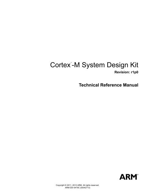
Introduction1.1 About the <strong>Cortex</strong>-M <strong>System</strong> <strong>Design</strong> <strong>Kit</strong>The <strong>Cortex</strong>-M <strong>System</strong> <strong>Design</strong> <strong>Kit</strong> helps you design products using <strong>ARM</strong> <strong>Cortex</strong>-M processors.The design kit contains the following:• A selection of AHB-Lite and APB components, including several peripherals such asGPIO, timers, watchdog, and UART.• An example system for supported processor products.• Example synthesis scripts for the example system.• Example compilation and simulation scripts for the Verilog environment that supportsModelSim, VCS, and NC Verilog.• Example code for software drivers.• Example test code to demonstrate various operations of the systems.• Example compilation scripts and example software project files that support:— <strong>ARM</strong> Development Studio 5 (DS-5).— <strong>ARM</strong> RealView Development Suite.— Keil Microcontroller Development <strong>Kit</strong> (MDK).— GNU Tools for <strong>ARM</strong> Embedded Processors (<strong>ARM</strong> GCC).• Documentation including:— <strong>Cortex</strong>-M <strong>System</strong> <strong>Design</strong> <strong>Kit</strong> <strong>Technical</strong> <strong>Reference</strong> <strong>Manual</strong>.— <strong>Cortex</strong>-M0 and <strong>Cortex</strong>-M0+ <strong>System</strong> <strong>Design</strong> <strong>Kit</strong> Example <strong>System</strong> Guide.— <strong>Cortex</strong>-M <strong>System</strong> <strong>Design</strong> <strong>Kit</strong> Example <strong>System</strong> Guide.Figure 1-1 shows the use of the design kit in various stages of a design process.PeripheralsdesignPeripheralsverificationSimulationenvironment<strong>Cortex</strong>-M <strong>System</strong><strong>Design</strong> <strong>Kit</strong>Simulation setupand software flow<strong>System</strong>-level verificationExample driver softwareEnhancementDevice driverlibraryReusable IPLicensed <strong>ARM</strong><strong>Cortex</strong>-MprocessorOut of boxtestingLearning to use<strong>ARM</strong> <strong>Cortex</strong>-MprocessorUsing <strong>Cortex</strong>-M<strong>System</strong> <strong>Design</strong> <strong>Kit</strong>as starting pointfor designEnhancementsMicrocontrollerFigure 1-1 <strong>Cortex</strong>-M <strong>System</strong> <strong>Design</strong> <strong>Kit</strong> usage in various stages of a design process<strong>ARM</strong> DDI 0479C Copyright © 2011, 2013 <strong>ARM</strong>. All rights reserved. 1-2ID042713Non-Confidential
IntroductionTable 1-1 shows the <strong>Cortex</strong>-M <strong>System</strong> <strong>Design</strong> <strong>Kit</strong> usage in various stages of a design process.Table 1-1 <strong>Cortex</strong>-M <strong>System</strong> <strong>Design</strong> <strong>Kit</strong> usage in various stages of a design processAreaOut of Box (OoB) testingLearningStarting point of designVerificationStarting point of software driverReusable IPDescriptionWhen you license the <strong>Cortex</strong>-M <strong>System</strong> <strong>Design</strong> <strong>Kit</strong> and a <strong>Cortex</strong>-M processor, you can use it forOoB testing and benchmarkingUsing the example systems, you can learn how to integrate the <strong>Cortex</strong>-M processor, and carry outvarious operationsYou can use the <strong>Cortex</strong>-M <strong>System</strong> <strong>Design</strong> <strong>Kit</strong> as a starting point to design your microcontrolleror <strong>System</strong>-on-Chip (SoC) productsYou can use the example system in the <strong>Cortex</strong>-M <strong>System</strong> <strong>Design</strong> <strong>Kit</strong> as a verification environmentto carry out system-level verificationYou can use the example software code in the <strong>Cortex</strong>-M <strong>System</strong> <strong>Design</strong> <strong>Kit</strong> as a starting point forsoftware driver developmentYou can reuse the various components of the <strong>Cortex</strong>-M <strong>System</strong> <strong>Design</strong> <strong>Kit</strong> in microcontroller orSoC design projectsThe <strong>Cortex</strong>-M <strong>System</strong> <strong>Design</strong> <strong>Kit</strong> is available as:• <strong>Cortex</strong>-M0 and <strong>Cortex</strong>-M0+ <strong>System</strong> <strong>Design</strong> <strong>Kit</strong>. This supports <strong>Cortex</strong>-M0, <strong>Cortex</strong>-M0<strong>Design</strong>Start, and <strong>Cortex</strong>-M0+.• <strong>Cortex</strong>-M <strong>System</strong> <strong>Design</strong> <strong>Kit</strong>, full version. This supports <strong>Cortex</strong>-M0, <strong>Cortex</strong>-M0<strong>Design</strong>Start, <strong>Cortex</strong>-M0+, <strong>Cortex</strong>-M3, and <strong>Cortex</strong>-M4.The other differences between the <strong>Cortex</strong>-M0 and <strong>Cortex</strong>-M0+ version, and the <strong>Cortex</strong>-Mversion of the design kit are the example systems, and the components provided. See Figure 1-2.<strong>Cortex</strong>-M <strong>System</strong> <strong>Design</strong> <strong>Kit</strong><strong>Cortex</strong>-M0 and <strong>Cortex</strong>-M0+ <strong>System</strong> <strong>Design</strong> <strong>Kit</strong>AHB components<strong>Cortex</strong>-M0 and<strong>Cortex</strong>-M0+example systemAPB componentsBehavioralmemory modelsI/O port GPIO*Advanced AHBcomponents<strong>Cortex</strong>-M3 and M4example systemAHB Bus Matrix* For use with the <strong>Cortex</strong>-M0+ directly, or as a subcomponent withinAHB GPIO module.The design supports the following bus protocols:Figure 1-2 Difference between the two versions of the design kit• AHB-Lite or AMBA 3 AHB-Lite Protocol v1.0. In this document, AHB signifiesAHB-Lite.• APB2 or AMBA 2 APB Protocol.• APB3 or AMBA 3 APB Protocol v1.0.• APB4 or AMBA APB Protocol v2.0.<strong>ARM</strong> DDI 0479C Copyright © 2011, 2013 <strong>ARM</strong>. All rights reserved. 1-3ID042713Non-Confidential
Introduction1.2 Product revisionsThis section describes the differences in functionality between product revisions of the<strong>Cortex</strong>-M <strong>System</strong> <strong>Design</strong> <strong>Kit</strong>:r0p0r0p0-r1p0First release.Functional changes are:• Support for <strong>Cortex</strong>-M0+ processor.• Added cmsdk_ prefix to module names.• CMSIS updated to version 3.2.• Changed HRESP width in some components.• AHB slave multiplexer changed from eight ports to ten ports. See AHBslave multiplexer on page 3-6.• Addition of I/O port GPIO for <strong>Cortex</strong>-M0+. See AHB GPIO on page 3-11.• Additional parameter in AHB to APB synchronous bridge. See AHB toAPB sync-down bridge on page 3-18.• Addition of AHB to AHB and APB asynchronous bridge. See AHB to AHBand APB asynchronous bridge on page 5-27.• Addition of 16-bit flash ROM behavioral model. See 16-bit flash ROMbehavioral model on page 6-12.<strong>ARM</strong> DDI 0479C Copyright © 2011, 2013 <strong>ARM</strong>. All rights reserved. 1-4ID042713Non-Confidential
Chapter 2Functional DescriptionThis chapter describes the major functional blocks of the <strong>Cortex</strong>-M <strong>System</strong> <strong>Design</strong> <strong>Kit</strong>. Itcontains the following sections:• About the <strong>Cortex</strong>-M <strong>System</strong> <strong>Design</strong> <strong>Kit</strong> components on page 2-2.• <strong>Design</strong> components on page 2-3.• Verification components on page 2-4.• ID registers in programmable components on page 2-5.• Use of OVL on page 2-6.<strong>ARM</strong> DDI 0479C Copyright © 2011, 2013 <strong>ARM</strong>. All rights reserved. 2-1ID042713Non-Confidential
Functional Description2.1 About the <strong>Cortex</strong>-M <strong>System</strong> <strong>Design</strong> <strong>Kit</strong> componentsThe <strong>Cortex</strong>-M <strong>System</strong> <strong>Design</strong> <strong>Kit</strong> provides example systems with AHB and APB componentsdesigned for low-power and low-latency designs.The preconfigured and validated examples enable you to develop devices in very short designcycles. In addition, you can reuse the components in future designs.<strong>ARM</strong> DDI 0479C Copyright © 2011, 2013 <strong>ARM</strong>. All rights reserved. 2-2ID042713Non-Confidential
Functional Description2.2 <strong>Design</strong> componentsThe example systems consist of the following components and models:• Basic AHB-Lite components.• APB components.• Advanced AHB-Lite components.• Behavioral memory models on page 2-4.• Verification components on page 2-4.2.2.1 Basic AHB-Lite componentsThe basic AHB-Lite components are:• AHB default slave.• AHB example slave.• AHB slave multiplexer.• AHB master multiplexer.• AHB General Purpose Input/Output (GPIO), including I/O port GPIO.• AHB to APB sync-down bridge.• AHB to SRAM interface module.• AHB to flash interface modules.• AHB timeout monitor.• AHB to external SRAM interface.• AHB bit-band wrapper for <strong>Cortex</strong>-M0 and <strong>Cortex</strong>-M0+.See Chapter 3 Basic AHB-Lite Components for more information.2.2.2 APB componentsThe APB components are:• APB example slave.• APB timer.• APB UART.• APB dual timer.• APB watchdog .• APB slave multiplexer.• APB subsystem.• APB timeout monitor.See Chapter 4 APB Components for more information.2.2.3 Advanced AHB-Lite componentsThe advanced AHB-Lite components are:• AHB bus matrix.• AHB upsizer.• AHB downsizer.• AHB to APB asynchronous bridge.• AHB to AHB and APB asynchronous bridge.• AHB to AHB synchronous bridge.• AHB to AHB sync-down bridge.• AHB to AHB sync-up bridge.<strong>ARM</strong> DDI 0479C Copyright © 2011, 2013 <strong>ARM</strong>. All rights reserved. 2-3ID042713Non-Confidential
Functional DescriptionNoteThe advanced AHB-Lite components are available only with the full version of the <strong>Cortex</strong>-M<strong>System</strong> <strong>Design</strong> <strong>Kit</strong>. They are not included in the <strong>Cortex</strong>-M0 and <strong>Cortex</strong>-M0+ <strong>System</strong> <strong>Design</strong><strong>Kit</strong>.See Chapter 5 Advanced AHB-Lite Components for more information.2.2.4 Behavioral memory modelsThe memory models are:• ROM model wrapper.• RAM model wrapper.• Behavioral SRAM model with AHB interface.• 32-bit flash ROM behavioral model.• 16-bit flash ROM behavioral model.• SRAM synthesizable (for FPGA) model.• FPGA ROM.• External asynchronous 8-bit SRAM.• External asynchronous 16-bit SRAM.See Chapter 6 Behavioral Memory Models for more information.2.2.5 Verification componentsThe verification components are:• AHB-Lite protocol checker.• APB protocol checker.• AHB File Reader Bus Master (FRBM).See Chapter 7 Verification Components for more information.<strong>ARM</strong> DDI 0479C Copyright © 2011, 2013 <strong>ARM</strong>. All rights reserved. 2-4ID042713Non-Confidential
Functional Description2.3 ID registers in programmable componentsIn the <strong>Cortex</strong>-M <strong>System</strong> <strong>Design</strong> <strong>Kit</strong>, some of the peripherals contain a number of read-onlyIdentification (ID) registers. These ID registers enable software to extract the component typeand revision information. In some cases, these registers are required to enable device driversoftware to work with different versions of the same peripherals.One of the ID registers, PID3, contains an Engineering Change Order (ECO) bit field generatedfrom the ECOREVNUM[3:0] input signal. The ECO operation enables you to carry out minordesign changes in the late stage of a chip design process, for example, at silicon mask level.Connect ECOREVNUM[3:0] to tie-off cells to support ECO revision maintenance.The ID registers are not strictly required for peripheral operation. In ultra low-power designs,you can remove these ID registers to reduce gate count and power consumption.When you modify a peripheral from the <strong>Cortex</strong>-M <strong>System</strong> <strong>Design</strong> <strong>Kit</strong>, modify the JEDEC IDvalue and the part number in the ID registers to indicate that the peripheral is no longer identicalto the original version from <strong>ARM</strong>. Alternatively, you can remove these ID registers.The JEDEC standard describes the JEDEC ID value allocation.2.3.1 Modification of componentsIn some applications, it is necessary to modify the design of some components. If this isrequired, <strong>ARM</strong> recommends that you do the following:• Change the component name and filename to avoid confusion, especially if you arerunning multiple projects using <strong>Cortex</strong>-M <strong>System</strong> <strong>Design</strong> <strong>Kit</strong> components.• Update the ID register values. See ID registers in programmable components.• Perform your own verification and testing.<strong>ARM</strong> DDI 0479C Copyright © 2011, 2013 <strong>ARM</strong>. All rights reserved. 2-5ID042713Non-Confidential
Functional Description2.4 Use of OVLThe components in the <strong>Cortex</strong>-M <strong>System</strong> <strong>Design</strong> <strong>Kit</strong> contain instantiations of Open VerificationLibrary (OVL) assertion components. The OVL assertions enable errors to be detected duringVerilog simulation.The instantiation of OVL assertions is conditional:AHB components This is controlled by the <strong>ARM</strong>_AHB_ASSERT_ON macro.APB componentsThis is controlled by the <strong>ARM</strong>_APB_ASSERT_ON macro.You can download the OVL source code from Accellera, www.accellera.org, if you use the OVLassertion feature.<strong>ARM</strong> DDI 0479C Copyright © 2011, 2013 <strong>ARM</strong>. All rights reserved. 2-6ID042713Non-Confidential
Chapter 3Basic AHB-Lite ComponentsThis chapter describes the basic AHB-Lite components provided in the <strong>Cortex</strong>-M <strong>System</strong><strong>Design</strong> <strong>Kit</strong>. It contains the following sections:• AHB default slave on page 3-2.• AHB example slave on page 3-3.• AHB slave multiplexer on page 3-6.• AHB master multiplexer on page 3-9.• AHB GPIO on page 3-11.• AHB to APB sync-down bridge on page 3-18.• AHB to SRAM interface module on page 3-20.• AHB to flash interface modules on page 3-22.• AHB timeout monitor on page 3-25.• AHB to external SRAM interface on page 3-27.• AHB bit-band wrapper on page 3-31.<strong>ARM</strong> DDI 0479C Copyright © 2011, 2013 <strong>ARM</strong>. All rights reserved. 3-1ID042713Non-Confidential
Basic AHB-Lite Components3.1 AHB default slaveThe AHB default slave, cmsdk_ahb_default_slave.v, responds to transfers when the bus masteraccesses an undefined address. A zero wait state OKAY response is generated for IDLE orBUSY transfers, and an ERROR response is generated for NONSEQUENTIAL orSEQUENTIAL transfers. Figure 3-1 shows the AHB default slave module.HCLKHRESETnHSELHTRANS[1:0]HREADYHREADYOUTHRESPcmsdk_ahb_default_slave.vTable 3-1 shows the characteristics of the AHB default slave module.Figure 3-1 AHB default slave componentTable 3-1 AHB default slave characteristicsElement nameFilenameParametersClock domainDescriptioncmsdk_ahb_default_slave.vNoneHCLK<strong>ARM</strong> DDI 0479C Copyright © 2011, 2013 <strong>ARM</strong>. All rights reserved. 3-2ID042713Non-Confidential
Basic AHB-Lite Components3.2 AHB example slaveThe AHB example slave, cmsdk_ahb_eg_slave.v, demonstrates the implementation of a simpleAHB slave, and consists of cmsdk_ahb_eg_slave_interface.v and cmsdk_ahb_eg_slave_reg.v.Figure 3-2 shows the AHB example slave module.cmsdk_ahb_eg_slave.vHCLKHRESETnHSELSHADDRS[ADDRWIDTH-1:0]HTRANSS[1:0]HSIZES[2:0]HWRITESHREADYSHWDATAS[31:0]HREADYOUTSHRESPSHRDATAS[31:0]cmsdk_ahb_eg_slave_interface.vAHBcmsdk_ahb_eg_slave_reg.vaddrread_enwrite_enbyte_strobewdatardataECOREVNUM[3:0]Simple register interfaceFigure 3-2 AHB example slaveThe AHB example slave has the following features:• 16 bytes of hardware RW registers organized as 4 words.• Register accesses in byte, halfword, and word transfers• Optional read-only Component ID and Peripheral ID registers. You must modify thefollowing in these registers:— Part number, 12 bits.— JEDEC ID value, 7 bits.• The ECOREVNUM input signal is connected to the ECO revision number in PeripheralID Register 3.• The interface block converts the AHB protocol to a simple non-pipelined bus protocol.You can reuse it for porting simple peripherals from 8-bit or 16-bit products to an<strong>ARM</strong>-based system.You can use the AHB example slave as a starting point for creating your own AHB peripherals,as follows:1. Copy the AHB example slave to a new directory, and rename the files to names of yourchoice.2. Remove the register block inside the AHB example slave, and replace with your ownperipheral register set.3. Add the additional peripheral functionality and I/O pins to the design.4. Instantiate the peripheral design in the system, and develop verification tests.<strong>ARM</strong> DDI 0479C Copyright © 2011, 2013 <strong>ARM</strong>. All rights reserved. 3-3ID042713Non-Confidential
Basic AHB-Lite ComponentsTable 3-2 shows the characteristics of the AHB example slave module.Table 3-2 AHB example slave characteristicsElement nameFilenameDescriptioncmsdk_ahb_eg_slave.vParameters ADDRWIDTH Width of the AHB address bus. The default is 12.Clock domainHCLK3.2.1 Programmers modelTable 3-3 shows the AHB example slave memory map.Name Base offset Type Width Reset value DescriptionDATA0 0x0000 RW 32 0x00000000 Simple Data Register.DATA1 0x0004 RW 32 0x00000000 Simple Data Register.DATA2 0x0008 RW 32 0x00000000 Simple Data Register.DATA3 0x000C RW 32 0x00000000 Simple Data Register.Table 3-3 AHB example slave memory mapPID4 0xFD0 RO 8 0x04 Peripheral ID Register 4:[7:4] 4KB block count.[3:0] jep106_c_code.PID5 a 0xFD4 RO 8 0x00 Peripheral ID Register 5.PID6 a 0xFD8 RO 8 0x00 Peripheral ID Register 6.PID7 a 0xFDC RO 8 0x00 Peripheral ID Register 7.PID0 0xFE0 RO 8 0x17 Peripheral ID Register 0:[7:0] Part number[7:0].PID1 0xFE4 RO 8 0xB8 Peripheral ID Register 1:[7:4] jep106_id_3_0.[3:0] Part number[11:8].PID2 0xFE8 RO 8 0x1B Peripheral ID Register 2:[7:4] Revision.[3] jedec_used.[2:0] jep106_id_6_4.PID3 0xFEC RO 8 0x00 Peripheral ID Register 3:[7:4] ECO revision number.[3:0] Customer modification number.CID0 0xFF0 RO 8 0x0D Component ID Register 0.CID1 0xFF4 RO 8 0xF0 Component ID Register 1.CID2 0xFF8 RO 8 0x05 Component ID Register 2.CID3 0xFFC RO 8 0xB1 Component ID Register 3.<strong>ARM</strong> DDI 0479C Copyright © 2011, 2013 <strong>ARM</strong>. All rights reserved. 3-4ID042713Non-Confidential
Basic AHB-Lite Componentsa. The PID5, PID6, and PID7 registers are not used.NoteSignals such as HPROT[3:0], HMASTLOCK, and HBURST[2:0] are not used in the design,so they do not appear in the AHB interface component.<strong>ARM</strong> DDI 0479C Copyright © 2011, 2013 <strong>ARM</strong>. All rights reserved. 3-5ID042713Non-Confidential
Basic AHB-Lite Components3.3 AHB slave multiplexerThe AHB slave multiplexer, cmsdk_ahb_slave_mux.v, supports up to ten AHB slaves. It usesparameters to define the slave port usage so that the synthesis process does not generateunnecessary additional logic. Figure 3-3 shows the AHB slave multiplexer.cmsdk_ahb_slave_mux.vfrom address decoderHCLKHRESETnHSEL0HSEL1HSEL9HREADYOUT0HRDATA0[DW-1:0]HRESP0HREADYOUT1HRDATA1[DW-1:0]HRESP1from AHB slavesHREADYHREADYOUTHRDATA[DW-1:0]HRESPHREADYOUT9HRDATA9[DW-1:0]HRESP9Figure 3-3 AHB slave multiplexerThe slave to master multiplexer controls the routing of read data and response signals from thesystem bus slaves to the bus masters. An address decoder determines the slave that is currentlyselected, and generates the HSEL signals to the AHB slave multiplexer and the AHB slaves.The multiplexer uses a registered version of the slave select signals, because the read data andresponse signals are valid during the data phase of a transfer, to connect the outputs of theselected slave to the inputs of the bus masters.When slaves are added to, or removed from, the system, you must modify the input connectionsand update the corresponding Verilog parameters to this module to adapt for the changes.<strong>ARM</strong> DDI 0479C Copyright © 2011, 2013 <strong>ARM</strong>. All rights reserved. 3-6ID042713Non-Confidential
Basic AHB-Lite ComponentsTable 3-4 shows the characteristics of the AHB slave multiplexer module.Table 3-4 AHB slave multiplexer characteristicsElement nameFilenameDescriptioncmsdk_ahb_slave_mux.vParameters PORT0_ENABLE The supported parameter values are:0 Disable port 0.1 Enable port 0.PORT1_ENABLE The supported parameter values are:0 Disable port 1.1 Enable port 1.PORT2_ENABLE The supported parameter values are:0 Disable port 2.1 Enable port 2.PORT3_ENABLE The supported parameter values are:0 Disable port 3.1 Enable port 3.PORT4_ENABLE The supported parameter values are:0 Disable port 4.1 Enable port 4.PORT5_ENABLE The supported parameter values are:0 Disable port 5.1 Enable port 5.PORT6_ENABLE The supported parameter values are:0 Disable port 6.1 Enable port 6.PORT7_ENABLE The supported parameter values are:0 Disable port 7.1 Enable port 7.PORT8_ENABLE The supported parameter values are:0 Disable port 8.1 Enable port 8.PORT9_ENABLE The supported parameter values are:0 Disable port 9.1 Enable port 9.NoteAll PORTn_ENABLE are set to 1 by default.DWData width. You can configure the width to either64 bits or 32 bits. This is set to 32 by default.Clock domainHCLKIf you require more AHB slave ports, you can either cascade two AHB slave multiplexers, orexpand the design.Figure 3-4 on page 3-8 shows the cascade connection of two AHB slave multiplexers in whichthe HSEL signals for slaves 10-18 are connected to HSEL1 to HSEL9 of the AHB slavemultiplexer 2. The HSEL0 of the AHB slave multiplexer 2 is an OR function of the HSELsignal for the AHB slaves 0-9.<strong>ARM</strong> DDI 0479C Copyright © 2011, 2013 <strong>ARM</strong>. All rights reserved. 3-7ID042713Non-Confidential
Basic AHB-Lite ComponentsAHB slave multiplexer 1HCLKcmsdk_ahb_slave_mux.vHADDRHRESETnHSEL0HREADYOUT0HRDATA0[DW-1:0]HRESP0AHB decoderHSEL1HREADYOUT1Set to 1 if any of AHBslave #0 to #9 isselectedHSEL9HREADYHRDATA1[DW-1:0]HRESP1from AHB slaves#0 to #9AHB slave multiplexer 2HCLKHRESETnHSEL0cmsdk_ahb_slave_mux.vHREADYOUT0HRDATA0[DW-1:0]HRESP0HREADYOUT9HRDATA9[DW-1:0]HRESP9HSEL1HREADYOUT1HRDATA1[DW-1:0]HSEL9HRESP1from AHB slaves #10 to #18to AHBmasterHREADYHREADYOUTHRDATA[DW-1:0]HRESPHREADYOUT9HRDATA9[DW-1:0]HRESP9Figure 3-4 Cascade connectionInstead of using multiple slave multiplexers, you can modify the design as follows:• Copy and rename the module.• Add ports for AHB slave connections.• Add Verilog parameters, such as PORTn_ENABLE if required.• Add the data phase select register, reg_hsel, and its next state logic.• Add ports to the slave signal multiplexing logic.• Adjust the optional OVL assertion code.<strong>ARM</strong> DDI 0479C Copyright © 2011, 2013 <strong>ARM</strong>. All rights reserved. 3-8ID042713Non-Confidential
Basic AHB-Lite Components3.4 AHB master multiplexerThe AHB master multiplexer, cmsdk_ahb_master_mux.v, permits up to three AHB masters toshare an AHB connection. It uses parameters to define the master port usage. Therefore, thesynthesis process does not generate unnecessary additional logic. Figure 3-5 shows the AHBmaster multiplexer.cmsdk_ahb_master_mux.vHCLKHRESETnHSELS0HADDRS0[31:0]HTRANSS0[1:0]HSIZES0[2:0]HWRITES0HREADYS0HPROTS0[3:0]HBURSTS0[2:0]HMASTLOCKS0HWDATAS0[DW-1:0]HREADYOUTS0HRESPS0HRDATAS0[DW-1:0]HSELMHADDRM[31:0]HTRANSM[1:0]HSIZEM[2:0]HWRITEMHREADYMHPROTM[3:0]HBURSTM[2:0]HMASTLOCKMHWDATAM[DW-1:0]HREADYOUTMHRESPMHRDATAM[DW-1:0]HMASTERM[1:0]HSELS1HADDRS1[31:0]HTRANSS1[1:0]HSIZES1[2:0]HWRITES1HREADYS1HPROTS1[3:0]HBURSTS1[2:0]HMASTLOCKS1HWDATAS1[DW-1:0]HREADYOUTS1HRESPS1HRDATAS1[DW-1:0]HSELS2HADDRS2[31:0]HTRANSS2[1:0]HSIZES2[2:0]HWRITES2HREADYS2HPROTS2[3:0]HBURSTS2[2:0]HMASTLOCKS2HWDATAS2[DW-1:0]HREADYOUTS2HRESPS2HRDATAS2[DW-1:0]Figure 3-5 AHB master multiplexer<strong>ARM</strong> DDI 0479C Copyright © 2011, 2013 <strong>ARM</strong>. All rights reserved. 3-9ID042713Non-Confidential
Basic AHB-Lite ComponentsTable 3-5 shows the characteristics of the AHB master multiplexer.Table 3-5 AHB master multiplexer characteristicsElement nameFilenameDescriptioncmsdk_ahb_master_mux.vParameters PORT0_ENABLE The supported parameter values are:0 Disable port 0.1 Enable port 0.PORT1_ENABLE The supported parameter values are:0 Disable port 1.1 Enable port 1.PORT2_ENABLE The supported parameter values are:0 Disable port 2.1 Enable port 2.NoteAll PORTn_ENABLE are set to 1 by default.DWData width. You can configure the width to either64 bits or 32 bits. This is set to 32 by default.Clock domainHCLK3.4.1 Arbitration schemeThe AHB master multiplexer uses a fixed arbitration scheme as follows:Port 0 Same priority as port 1, round-robin scheme.Port 1 Same priority as port 0, round-robin scheme.Port 2 Higher priority master.Switch-over between different masters is disabled during a fixed length burst, locked transfers,or if a transfer is indicated to the AHB slaves at the same time as a wait state occurs on the bus.You can break an incrementing burst with an unspecified length into multiple parts as a resultof arbitration. The master multiplexer forces HTRANS to NONSEQUENTIAL for the firsttransfer after switching to ensure that the AHB protocol operates correctly.3.4.2 LimitationsThe AHB master multiplexer has the following limitations:• The downstream slave must respond with HREADYOUTM HIGH and HRESPMOKAY when it is not selected.3.4.3 HMASTERM outputThe AHB master multiplexer provides an HMASTERM[1:0] output signal that indicates whichport a transfer originated from:2’b00 Port 0.2’b01 Port 1.2’b10 Port 2.2’b11 None.<strong>ARM</strong> DDI 0479C Copyright © 2011, 2013 <strong>ARM</strong>. All rights reserved. 3-10ID042713Non-Confidential
Basic AHB-Lite Components3.5 AHB GPIOThe AHB GPIO, cmsdk_ahb_gpio.v, is a general-purpose I/O interface unit.The AHB GPIO provides a 16-bit I/O interface with the following properties:• Programmable interrupt generation capability.• Bit masking support using address values.• Registers for alternate function switching with pin multiplexing support.• Thread safe operation by providing separate set and clear addresses for control registers.• Inputs are sampled using a double flip-flop to avoid metastability issues.Figure 3-6 shows the control circuit and external interface of the AHB GPIO.cmsdk_ahb_gpio.vcmsdk_ahb_io_bridge.vcmsdk_io_gpio.v*FCLKHCLKHRESETnHSELHADDR[11:0]HTRANS[1:0]HSIZE[2:0]HWRITEPORTIN[15:0]PORTOUT[15:0]PORTEN[15:0]01HREADYHWDATA[31:0]HREADYOUTHRESPHRDATA[31:0]ECOREVNUM[3:0]PORTFUNC[15:0]GPIOINT[15:0]COMBINT01Pin MuxI/O pad* If using the I/O GPIO for the <strong>Cortex</strong>-M0+ processorAlternatefunction signalsTable 3-6 shows the characteristics of the AHB GPIO.Figure 3-6 AHB GPIO control circuit and external interfaceTable 3-6 AHB GPIO characteristicsElement nameFilenameParametersClock domainsDescriptioncmsdk_ahb_gpio.vALTERNATE_FUNC_MASKIndicates the pin that can have an alternate function. This parameter is set to 16’hFFFF by default.This means that all 16 pins can have alternate functions.ALTERNATE_FUNC_DEFAULTDefault value for alternate function setting. This parameter is set to 16’h0000 by default. Thismeans that all pins are used for the GPIO function after reset.BEBig-endian. The default value is 0 for little-endian. Set the value to 1 for big-endian configuration.The clock domains are as follows:HCLK AHB-Lite system clock. Can be gated off during sleep mode.FCLK Free running clock, in same phase as HCLK. Must be running to generate edge trigger interrupt.<strong>ARM</strong> DDI 0479C Copyright © 2011, 2013 <strong>ARM</strong>. All rights reserved. 3-11ID042713Non-Confidential
Basic AHB-Lite Components3.5.1 Features of the GPIOThe following sections describe the features of the GPIO:• Interrupt generation• Masked access.Interrupt generationThe AHB GPIO provides programmable interrupt generation features. Three registers controlthis, and each register has separate set and clear addresses. You can configure each bit of the I/Opins to generate interrupts based on these three registers. See Table 3-7.Table 3-7 Interrupt generationInterrupt enable[n] Interrupt polarity[n] Interrupt type[n] Interrupt feature0 - - Disabled1 0 0 Low-level1 0 1 Falling edge1 1 0 High-level1 1 1 Rising edgeAfter an interrupt is triggered, the corresponding bit in the INTSTATUS Register is set. This alsocauses the corresponding bit of the GPIOINT[15:0] signal to be asserted. As a result, thecombined interrupt signal, COMBINT, is also asserted. You can clear the interrupt status usingan interrupt handler that writes 1 to the corresponding bit of the INTCLEAR Register, the sameaddress as the INTSTATUS Register.NoteThe free running clock signal, FCLK, must be active during interrupt detection, because of thedouble flip-flop synchronization logic. There is also a three cycle latency for the interruptgeneration that consists of two cycles for input signal synchronization, and one cycle forregistering of the interrupt status.Masked accessThe masked access feature permits individual bits or multiple bits to be read from or written toin a single transfer. This avoids software-based read-modify-write operations that are not threadsafe. With the masked access operations, the 16-bit I/O is divided into two halves, lower byteand upper byte. The bit mask address spaces are defined as two arrays, each containing 256words.For example, to set bits[1:0] to 1 and clear bits[7:6] in a single operation, you can carry out thewrite to the lower byte mask access address space. The required bit mask is 0xC3, and you canwrite the operation as MASKLOWBYTE[0xC3] = 0x03 as Figure 3-7 on page 3-13 shows.<strong>ARM</strong> DDI 0479C Copyright © 2011, 2013 <strong>ARM</strong>. All rights reserved. 3-12ID042713Non-Confidential
Basic AHB-Lite ComponentsGPIOOUT[15:0] was 0x32E8ID registersAddressoffset0x0FC0Set bits [1:0] to 1Clear bits [7:6] to 0Bit mask = ‘b11000011 (0xC3)Upper byte maskedaccessGPIOOUT[15:0] becomes 0x322BAddress offset =0x0400 + 0xC3*4 = 0x70COperation: MASKLOWBYTE[0xC3] = 0x03MASKLOWBYTE is a dataarray of 32-bit x 256Lower byte maskedaccess0x08000x0400Data and Controlregisters0x0000Figure 3-7 Masked access 1Similarly, to update some of the bits in the upper eight bits of the GPIO port, you can use theMASKHIGHBYTE array as Figure 3-8 shows.GPIOOUT[15:0] was 0x322BClear bits [12:11] to 0Set bits [15] to 1Bit mask = b10011000 (0x98)ID registersAddressoffset0x0FC0GPIOOUT[15:0] becomes 0xA22BOperation: MASKHIGHBYTE[0x98] = 0x8000Address offset =0x0800 + 0x98*4 = 0xA60Upper byte maskedaccessMASKHIGHBYTE is a data arrayof 32-bit x 256Lower byte maskedaccess0x08000x0400Data and Controlregisters0x0000Figure 3-8 Masked access 2<strong>ARM</strong> DDI 0479C Copyright © 2011, 2013 <strong>ARM</strong>. All rights reserved. 3-13ID042713Non-Confidential
Basic AHB-Lite Components3.5.2 Programmers modelTable 3-8 shows the software programmable registers in the example AHB GPIO.Name Base offset Type Width Reset value DescriptionTable 3-8 GPIO memory mapDATA 0x0000 RW 16 0x---- Data value [15:0]:Read Sampled at pin.Write To data output register.Read back value goes through double flip-flopsynchronization logic with a delay of two cycles.DATAOUT 0x0004 RW 16 0x0000 Data output Register value [15:0]:Read Current value of data output register.Write To data output register.Reserved 0x0008-0x000C - - - Reserved.OUTENSET 0x0010 RW 16 0x0000 Output enable set [15:0]:Write 1 Set the output enable bit.0 No effect.Read back 0 Indicates the signaldirection as input.1 Indicates the signaldirection as output.OUTENCLR 0x0014 RW 16 0x0000 Output enable clear [15:0]:Write 1 Clears the output enablebit.0 No effect.Read back 0 Indicates the signaldirection as input.1 Indicates the signaldirection as output.ALTFUNCSET 0x0018 RW 16 0x0000 Alternative function set [15:0]:Write 1 Sets the ALTFUNC bit.0 No effect.Read back 0 For I/O.1 For an alternate function.ALTFUNCCLR 0x001C RW 16 0x0000 Alternative function clear [15:0]:Write 1 Clears the ALTFUNC bit.0 No effect.Read back 0 For I/O.1 For an alternate function.INTENSET 0x0020 RW 16 0x0000 Interrupt enable set [15:0]:Write 1 Sets the enable bit.0 No effect.Read back 0 Interrupt disabled.1 Interrupt enabled.<strong>ARM</strong> DDI 0479C Copyright © 2011, 2013 <strong>ARM</strong>. All rights reserved. 3-14ID042713Non-Confidential
Basic AHB-Lite ComponentsTable 3-8 GPIO memory map (continued)Name Base offset Type Width Reset value DescriptionINTENCLR 0x0024 RW 16 0x0000 Interrupt enable clear [15:0]:Write 1 Clear the enable bit.0 No effect.Read back 0 Interrupt disabled.1 Interrupt enabled.INTTYPESET 0x0028 RW 16 0x0000 Interrupt type set [15:0]:Write 1 Sets the interrupt type bit.0 No effect.Read back 0 For LOW or HIGH level.1 For falling edge or risingedge.INTTYPECLR 0x002C RW 16 0x0000 Interrupt type clear [15:0]:Write 1 Clears the interrupt typebit.0 No effect.Read back 0 For LOW or HIGH level.1 For falling edge or risingedge.INTPOLSET 0x0030 RW 16 0x0000 Polarity-level, edge IRQ configuration [15:0]:Write 1 Sets the interrupt polaritybit.0 No effect.Read back 0 For LOW level or fallingedge.1 For HIGH level or risingedge.INTPOLCLR 0x0034 RW 16 0x0000 Polarity-level, edge IRQ configuration [15:0]:Write 1 Clears the interruptpolarity bit.0 No effect.Read back 0 For LOW level or fallingedge.1 For HIGH level or risingedge.INTSTATUS,INTCLEAR0x0038 RW 16 0x0000 Write one to clear interrupt request:Write [15:0] IRQ status clear Register.Write:1 To clear the interruptrequest.0 No effect.Read back [15:0] IRQ status Register.<strong>ARM</strong> DDI 0479C Copyright © 2011, 2013 <strong>ARM</strong>. All rights reserved. 3-15ID042713Non-Confidential
Basic AHB-Lite ComponentsName Base offset Type Width Reset value DescriptionMASKLOWBYTE 0x0400-0x07FC RW 16 0x---- Lower eight bits masked access. Bits[9:2] of theaddress value are used as enable bit mask for theaccess:[15:8] Not used. RAZ/WI.[7:0] Data for lower byte access, withbits[9:2] of address value used asenable mask for each bit.MASKHIGHBYTE 0x0800-0x0BFC RW 16 0x---- Higher eight bits masked access. Bits[9:2] of theaddress value are used as enable bit mask for theaccess:[15:8] Data for higher byte access, withbits[9:2] of address value used asenable mask for each bit.[7:0] Not used. RAZ/WI.Reserved 0x0C00 - 0x0FCF - - - Reserved.PID4 0x0FD0 RO 8 0x04 Peripheral ID Register 4:[7:4] Block count.[3:0] jep106_c_code.PID5 a 0x0FD4 RO - 0x00 Peripheral ID Register 5.PID6 a 0x0FD8 RO - 0x00 Peripheral ID Register 6.PID7 a 0x0FDC RO - 0x00 Peripheral ID Register 7.PID0 0x0FE0 RO 8 0x20 Peripheral ID Register 0:[7:0] Part number[7:0].PID1 0x0FE4 RO 8 0xB8 Peripheral ID Register 1:[7:4] jep106_id_3_0.[3:0] Part number[11:8].PID2 0x0FE8 RO 8 0x1B Peripheral ID Register 2:[7:4] Revision.[3] jedec_used.[2:0] jep106_id_6_4.PID3 0x0FEC RO 8 0x00 Peripheral ID Register 3:[7:4] ECO revision number.[3:0] Customer modification number.CID0 0x0FF0 RO 8 0x0D Component ID Register 0.CID1 0x0FF4 RO 8 0xF0 Component ID Register 1.CID2 0x0FF8 RO 8 0x05 Component ID Register 2.CID3 0x0FFC RO 8 0xB1 Component ID Register 3.a. The PID5, PID6, and PID7 registers are not used.Table 3-8 GPIO memory map (continued)<strong>ARM</strong> DDI 0479C Copyright © 2011, 2013 <strong>ARM</strong>. All rights reserved. 3-16ID042713Non-Confidential
Basic AHB-Lite Components3.5.3 Component dependencyFor use with the <strong>Cortex</strong>-M0+ processor, the AHB GPIO contains an AHB to single-cycle I/Ointerface adaptor, and a GPIO module with a single-cycle I/O interface. To use this module inyour design, add cmsdk_ahb_gpio/verilog and cmsdk_iop_gpio/verilog in the search path, orexplicitly include the Verilog RTL files in these two directories in your project.<strong>ARM</strong> DDI 0479C Copyright © 2011, 2013 <strong>ARM</strong>. All rights reserved. 3-17ID042713Non-Confidential
Basic AHB-Lite Components3.6 AHB to APB sync-down bridgeThe AHB to APB sync-down bridge, cmsdk_ahb_to_apb.v, has the following features:• Supports APB2, APB3, and APB4.• Runs the APB interface semi-synchronously slower than the AHB interface.Figure 3-9 shows the AHB to APB sync-down bridge.cmsdk_ahb_to_apb.vHCLKHRESETnPCLKENAPBACTIVEHSELHADDR[ADDRWIDTH-1:0]HTRANS[1:0]HSIZE[2:0]HPROT[3:0]HWRITEHREADYHWDATA[31:0]HREADYOUTHRESPHRDATA[31:0]PADDR[ADDRWIDTH-1:0]PENABLEPSELPWRITEPSTRB[3:0]PPROT[2:0]PWDATA[31:0]PREADYPSLVERRPRDATA[31:0]Figure 3-9 AHB to APB sync-down bridgeTable 3-9 shows the characteristics of the AHB to APB sync-down bridge module.Table 3-9 AHB to APB sync-down bridge characteristicsElement nameFilenameDescriptioncmsdk_ahb_to_apb.vParameters ADDRWIDTH APB address width. The default value is 16, that is, 64K byte APB address space.REGISTER_RDATA 1 Registered read data path.0 Combinational read data path.The default value is 1.REGISTER_WDATA 1 Registered write data path.0 Combinational write data path.Registering write data can help reduce timing issues caused by large fanouts. Thedefault value is 0.Clock domainHCLKThe AHB to APB bridge has an output called APBACTIVE that controls the clock gating cellfor generation of a gated PCLK. The gated PCLK is called PCLKG in the example system.When there is no APB transfer, this signal is LOW and stops PCLKG. Peripherals designedwith separate clock pins for bus logic and peripheral operation can use the gated PCLK toreduce power consumption.This block requires an APB clock synchronized to HCLK. PCLK can be divided or the sameas HCLK by using PCLKEN.When developing a system for AMBA 2.0, you can tie PSLVERR LOW, and PREADY HIGH.<strong>ARM</strong> DDI 0479C Copyright © 2011, 2013 <strong>ARM</strong>. All rights reserved. 3-18ID042713Non-Confidential
Basic AHB-Lite ComponentsWhen using APB2 and APB3 peripheral systems, you can ignore the PPROT[2:0] and thePSTRB[3:0] signals.For systems that do not require a high operating frequency, you can override the REGISTER_RDATAVerilog parameter to 0 to reduce the latency of APB accesses. This results in the read data fromthe APB slaves, PRDATA, being directly output to the AHB read data output, HRDATA, andreduces the wait states in addition to the gate counts. By default, the REGISTER_RDATA parameteris set to 1 to include a registering stage.For a system with HCLK equal to PCLK, and if there is no error response from APB slaves,the minimum number of cycles for each RW is as follows:• Three HCLK cycles when REGISTER_RDATA is 1.• Two HCLK cycles when REGISTER_RDATA is 0.For systems that require a high operating frequency, set the REGISTER_WDATA Verilog parameterto 1 to register the AHB master write data. This breaks the path between HWDATA andPWDATA but increases the latency of write transfers by one cycle.<strong>ARM</strong> DDI 0479C Copyright © 2011, 2013 <strong>ARM</strong>. All rights reserved. 3-19ID042713Non-Confidential
Basic AHB-Lite Components3.7 AHB to SRAM interface moduleThe AHB to SRAM interface module, cmsdk_ahb_to_sram.v, enables on-chip synchronousSRAM blocks to attach to an AHB interface. It performs read and write operations with zerowait states. The design supports 32-bit SRAM only. The SRAM must support byte writes. Youcan also use this module in FPGA development for connecting FPGA block RAM to the AHB.Figure 3-10 shows the AHB to SRAM interface module.cmsdk_ahb_to_sram.vHCLKHRESETnHSELHADDR[AW-1:0]HTRANS[1:0]HSIZE[2:0]HWRITEHREADYHWDATA[31:0]HREADYOUTHRESPHRDATA[31:0]SRAMADDR[AW-3:0]SRAMWEN[3:0]SRAMCSSRAMWDATA[31:0]SRAMRDATA[31:0]Figure 3-10 AHB to SRAM interface moduleTable 3-10 shows the characteristics of the AHB to SRAM interface module.Table 3-10 AHB to SRAM interface module characteristicsElement nameFilenameDescriptioncmsdk_ahb_to_sram.vParameters AW Address width. The default value is 16, that is, 64KB. For example, if the SRAMis 8KB, set AW to 13.Clock domainHCLKThe design always responds with OKAY and zero wait states.The AHB to SRAM interface module assumes the SRAM read and write access timings thatFigure 3-11 on page 3-21 shows.<strong>ARM</strong> DDI 0479C Copyright © 2011, 2013 <strong>ARM</strong>. All rights reserved. 3-20ID042713Non-Confidential
Basic AHB-Lite ComponentsHCLKHSELHADDRaddraddrHTRANSHWRITENSEQ/SEQNSEQ/SEQHREADYHRDATAdataHWDATASRAMADDRaddrdataaddrSRAMCSSRAMWENSRAMWDATAdataSRAMRDATAdataRead address and read controlsignals applyFetch read dataWrite address, data and write controlsignals applyFigure 3-11 SRAM interface timingIf a read operation follows immediately after a write operation, the write address and write dataare stored in an internal buffer, and the SRAM carries out the read operation first. The stalledwrite transfer is carried out when the AHB interface is idle, or when there is a write transfer.A merging of read data between the internal buffers and the read data from SRAM is carried outautomatically by the interface module, when:• A read operation follows immediately after a write operation to the same address.• A sequence of read operations follows immediately after a write operation with any of theread transfers using the same address.The merging processing uses internal buffer byte valid status and ensures the read data thatreturns to the bus master is up-to-date. This process occurs transparently and does not result inany wait states.<strong>ARM</strong> DDI 0479C Copyright © 2011, 2013 <strong>ARM</strong>. All rights reserved. 3-21ID042713Non-Confidential
Basic AHB-Lite Components3.8 AHB to flash interface modulesThe AHB to flash interface modules, cmsdk_ahb_to_flash32.v and cmsdk_ahb_to_flash16.v,enable you to connect a simple 32-bit or 16-bit read-only flash memory model to an AHBsystem. They include parameterized wait state generation.Figure 3-12 shows the AHB to flash interface module for 32-bit flash ROM.cmsdk_ahb_to_flash32.vHCLKHRESETnHSELHADDR[AW-1:0]HTRANS[1:0]HSIZE[2:0]HPROT[3:0]HWRITEHREADYHWDATA[31:0]HREADYOUTHRESPHRDATA[31:0]FLASHADDR[AW-3:0]FLASHRDATA[31:0]Figure 3-12 AHB to flash interface module for 32-bit flash ROMTable 3-12 on page 3-23 shows the characteristics of the AHB to flash interface module for32-bit flash ROM.Table 3-11 AHB to flash interface module for 32-bit flash ROM characteristicsElement nameFilenameDescriptioncmsdk_ahb_to_flash32.vParameters AW Address width. The default value is 16.WS Wait state. The default value is 1. The valid range of wait state is 0-3.Clock domainHCLKFigure 3-13 on page 3-23 shows the AHB to flash interface module for 16-bit flash ROM. Thismodule is design to work with 16-bit AHB. A 32-bit AHB to 16-bit AHB downsizer is availablein the <strong>Cortex</strong>-M0+ deliverable. Inside the integration kit, the filename is cm0p_32to16_dnsize.v.<strong>ARM</strong> DDI 0479C Copyright © 2011, 2013 <strong>ARM</strong>. All rights reserved. 3-22ID042713Non-Confidential
Basic AHB-Lite Componentscmsdk_ahb_to_flash16.vHCLKHRESETnHSELHADDR[AW-1:0]HTRANS[1:0]HSIZE[2:0]HPROT[3:0]HWRITEHREADYHWDATA[15:0]HREADYOUTHRESPHRDATA[15:0]FLASHADDR[AW-2:0]FLASHRDATA[15:0]Figure 3-13 AHB to flash interface module for 16-bit flash ROMTable 3-12 shows the characteristics of the AHB to flash interface module for 16-bit flash ROM.Table 3-12 AHB to flash interface module for 16-bit ROM characteristicsElement nameFilenameDescriptioncmsdk_ahb_to_flash16.vParameters AW Address width. The default value is 16.WS Wait state. The default value is 1. The valid range of wait state is 0-3.Clock domainHCLKThis interface module only supports read operations.Figure 3-14 on page 3-24 shows the flash memory read access timings with different wait states.<strong>ARM</strong> DDI 0479C Copyright © 2011, 2013 <strong>ARM</strong>. All rights reserved. 3-23ID042713Non-Confidential
Basic AHB-Lite ComponentsFlash memory read with WS = 0Flash memory read with WS = 1HCLKHCLKHSELHSELHADDRNHADDRNHTRANSNONSEQHTRANSNONSEQHWRITEHWRITEHREADYHREADYHREADYOUTHREADYOUTHRDATAHRDATAFLASHADDRNFLASHADDRNFLASHRDATAFLASHRDATAFigure 3-14 AHB to flash read access timing<strong>ARM</strong> DDI 0479C Copyright © 2011, 2013 <strong>ARM</strong>. All rights reserved. 3-24ID042713Non-Confidential
Basic AHB-Lite Components3.9 AHB timeout monitorThe AHB timeout monitor, cmsdk_ahb_timeout_mon.v, prevents an AHB slave from locking up asystem. It is placed between the AHB master and slave, and is connected directly to the AHBslave. If there is an active transfer to the slave, and the slave holds HREADY LOW for morethan a certain number of clock cycles, the monitor generates an error response to the bus master.Figure 3-15 shows the AHB timeout monitor module.If the bus master generates any subsequent access to this slave, the monitor returns an errorresponse, and blocks access to the slave. The timeout monitor stops generating error responsesand masking access to the slave when the slave has completed the transfer that timed out byasserting HREADYOUT HIGH. If a burst is in progress, the timeout monitor masks theremaining beats in the burst before becoming transparent again.HCLKHRESETncmsdk_ahb_timeout_mon.vHSELSHTRANSS[1:0]HREADYSHREADYOUTSHRESPSTIMEOUTHSELMHTRANSM[1:0]HREADYMHREADYOUTMHRESPMFigure 3-16 shows the typical usage of the AHB timeout monitor.Figure 3-15 AHB timeout monitorAHB master AHB interconnect AHB timeout monitorAHB slaveFigure 3-16 Use of AHB timeout monitorIf the monitor is directly coupled to the processor, or connected to an AHB path that is used forexception handler code access, the processor cannot execute the bus fault exception handler.If multiple bus slaves require monitoring, <strong>ARM</strong> recommends that you use multiple monitorsinstead of putting one monitor at the AHB slave multiplexer connection, to prevent the monitorfrom blocking access to the program ROM or SRAM.The TIME_OUT_VALUE Verilog parameter determines the number of wait state cycles that triggerthe timeout.You can use the TIMEOUT output signal to export timeout events to external logic. Duringtimeout, the TIMEOUT signal is asserted continuously until the AHB slave asserts theHREADYOUT signal.Table 3-13 on page 3-26 shows the characteristics of the AHB timeout monitor.<strong>ARM</strong> DDI 0479C Copyright © 2011, 2013 <strong>ARM</strong>. All rights reserved. 3-25ID042713Non-Confidential
Basic AHB-Lite ComponentsTable 3-13 AHB timeout monitor characteristicsElement nameFilenameDescriptioncmsdk_ahb_timeout_mon.vParameters TIME_OUT_VALUE Number of wait cycles that trigger timeout. Permitted values for thisparameter are 2-1024 inclusive. The default value is 16.Clock domainHCLK<strong>ARM</strong> DDI 0479C Copyright © 2011, 2013 <strong>ARM</strong>. All rights reserved. 3-26ID042713Non-Confidential
Basic AHB-Lite Components3.10 AHB to external SRAM interfaceThe AHB to external SRAM interface module, cmsdk_ahb_to_extmem16.v, enables externalSRAM, static memory devices or external peripherals, to connect to the <strong>Cortex</strong>-M processordesign. The module supports only 16-bit and 8-bit external interfaces. Figure 3-17 shows theAHB to external SRAM interface module.cmsdk_ahb_to_extmem16.vHCLKHRESETnHSELHADDR[AW-1:0]HTRANS[1:0]HSIZE[2:0]HWRITEHREADYHWDATA[31:0]HREADYOUTHRESPHRDATA[31:0]CFGREADCYCLE[2:0]CFGWRITECYCLE[2:0]CFGTURNAROUNDCYCLE[2:0]CFGSIZEADDR[AW-1:0]DATAOUT[15:0]DATAOEnDATAIN[15:0]WEnOEnCEnLBnUBnFigure 3-17 AHB to external SRAM interfaceThe interface module, cmsdk_ahb_to_extmem16.v, is designed to support an external bidirectionaldata bus. The DATAOEn signal controls the tristate buffer for data output. You must add yourown tristate buffers in your system implementation. The design enables turnaround cycles to beinserted between reads and writes to prevent current spikes that could occur for a very short timewhen the processor system and the external device both drive the data bus. The followingsignals control wait states for reads, wait states for writes, and the number of turnaround cyclesrespectively:• CFGREADCYCLE.• CFGWRITECYCLE.• CFGTURNAROUNDCYCLE.You can operate the interface module in 8-bit mode, with CFGSIZE LOW, or 16-bit mode, withCFGSIZE HIGH. All the configuration control signals must remain stable during operation.The design generates an OKAY response.Table 3-14 shows the characteristics of the AHB to external SRAM interface.Table 3-14 AHB to external SRAM interface characteristicsElement nameFilenameDescriptioncmsdk_ahb_to_extmem16.vParameters AW Address width. The default value is 16.Clock domainHCLK<strong>ARM</strong> DDI 0479C Copyright © 2011, 2013 <strong>ARM</strong>. All rights reserved. 3-27ID042713Non-Confidential
Basic AHB-Lite Components3.10.1 Signal descriptionsTable 3-15 shows the non-AMBA signals that the AHB to external SRAM interface uses.Table 3-15 AHB to external SRAM interface signalsSignalCFGREADCYCLE[2:0]CFGWRITECYCLE[2:0]CFGTURNAROUNDCYCLE[2:0]DescriptionNumber of clock cycles for a read operation. A value of 0 indicates one read cycle.Number of clock cycles for a write operation. A value of 0 indicates one write cycle. Theinterface module automatically inserts one additional setup cycle before the write and onehold cycle after the write.Number of clock cycles required to switch between a read and a write operation on the tristatebus. A value of 0 indicates one turnaround cycle.CFGSIZESet:LOWHIGHFor 8-bit memory.For 16-bit memory.DATAOEnWEnOEnCEnLBnUBnTristate buffer output enable for DATAOUT. Active LOW.Write strobe for external memory device. Active LOW.Read access output enable for external memory device. Active LOW.Chip enable. Active LOW.Lower byte enable. Active LOW.Upper byte enable. Active LOW.Figure 3-18 on page 3-29 shows the external SRAM interface timing for the following signals.These are the control wait states for reads, wait states for writes, and the number of turnaroundcycles respectively:• CFGREADCYCLE=0.• CFGWRITECYCLE=0.• CFGTURNAROUNDCYCLE=0.<strong>ARM</strong> DDI 0479C Copyright © 2011, 2013 <strong>ARM</strong>. All rights reserved. 3-28ID042713Non-Confidential
Basic AHB-Lite ComponentsHCLKHSELHADDRA1A2HTRANSNONSEQNONSEQHWRITEHWDATAD2 (valid)HREADYHREADYOUTHRDATAD1ADDRA1A2DATAOEnDATAOUTD2 (valid)CEnOEnUBn, LBnWEnDATAIND1ReadoperationBus turnaroundcycleWriteoperationFigure 3-18 External SRAM interface timing 1Figure 3-19 on page 3-30 shows the external SRAM interface timing for the following signals.These are the control wait states for reads, wait states for writes, and the number of turnaroundcycles respectively:• CFGREADCYCLE=1, that is, two cycles.• CFGWRITECYCLE=1, that is, two cycles.• CFGTURNAROUNDCYCLE=1, that is, two cycles.<strong>ARM</strong> DDI 0479C Copyright © 2011, 2013 <strong>ARM</strong>. All rights reserved. 3-29ID042713Non-Confidential
Basic AHB-Lite ComponentsHCLKHSELHADDRA1A2HTRANSNONSEQNONSEQHWRITEHWDATAD2 (valid)HREADYHREADYOUTHRDATAD1ADDRA1A2DATAOEnDATAOUTD2 (valid)CEnOEnUBn, LBnWEnDATAIND1Read operation Bus turnaround cycles Write operationFigure 3-19 External SRAM interface timing 2<strong>ARM</strong> DDI 0479C Copyright © 2011, 2013 <strong>ARM</strong>. All rights reserved. 3-30ID042713Non-Confidential
Basic AHB-Lite Components3.11 AHB bit-band wrapperThe AHB bit-band wrapper, cmsdk_ahb_bitband.v, provides the bit-band functionality for the<strong>Cortex</strong>-M0 and <strong>Cortex</strong>-M0+ processor.NoteThe bit-band wrapper is provided as a workaround for designers who are migrating silicondesigns from a <strong>Cortex</strong>-M3 or <strong>Cortex</strong>-M4 processor to a <strong>Cortex</strong>-M0 or <strong>Cortex</strong>-M0+ processor,and require software compatibility with the <strong>Cortex</strong>-M3 and <strong>Cortex</strong>-M4 bit-band feature. Usingthe bit-band wrapper can result in the following:• Longer timing paths on AHB interconnect and therefore a reduction in the maximumclock frequency.• Higher power consumption.• Larger design size.<strong>ARM</strong> recommends that bit level access functionality is designed into any peripherals that canbenefit from fast bit set and clear operations rather than using the bit-band wrapper.Figure 3-20 shows the AHB bit-band wrapper module for the <strong>Cortex</strong>-M0 and <strong>Cortex</strong>-M0+processor.HCLKHRESETncmsdk_ahb_bitband.vHSELSHADDRS[31:0]HTRANSS[1:0]HPROTS[3:0]HBURSTS[2:0]HMASTLOCKSHMASTERS[MW-1:0]HSIZES[2:0]HWRITESHREADYSHWDATAS[31:0]HREADYOUTSHRESPSHRDATAS[31:0]HSELMHADDRM[31:0]HTRANSM[1:0]HPROTM[3:0]HBURSTM[2:0]HMASTLOCKMHMASTERM[MW-1:0]HSIZEM[2:0]HWRITEMHREADYMHWDATAM[31:0]HREADYOUTMHRESPMHRDATAM[31:0]Figure 3-20 AHB bit-band wrapper for <strong>Cortex</strong>-M0 and <strong>Cortex</strong>-M0+ processor<strong>ARM</strong> DDI 0479C Copyright © 2011, 2013 <strong>ARM</strong>. All rights reserved. 3-31ID042713Non-Confidential
Basic AHB-Lite ComponentsTable 3-16 shows the characteristics of the AHB bit-band wrapper for the <strong>Cortex</strong>-M0 and<strong>Cortex</strong>-M0+ processor.Table 3-16 AHB bit-band wrapper for <strong>Cortex</strong>-M0 processor characteristicsElement nameFilenameDescriptioncmsdk_ahb_bitband.vParameters MW Width of HMASTER signals. The default value is 1 because HMASTER in the <strong>Cortex</strong>-M0 and<strong>Cortex</strong>-M0+ processor is a one-bit signal.BEBig-endian. The default value is 0 for little-endian. Set the value to 1 for big-endian configuration.Clock domainHCLKWhen an AHB data transfer goes to bit-band alias regions 0x22000000 to 0x23FFFFFFC or0x42000000 to 0x43FFFFFFC, the transfer is remapped to bit-band regions 0x20000000 to 0x200FFFFFor 0x40000000 to 0x400FFFFF.If the transfer is a read operation, a single remapped read transfer is produced, and the LeastSignificant Bit (LSB) of the read data indicates the bit value read. If the transfer is a writeoperation, the transfer is converted into a locked read-modify-write sequence.The written bit is replaced by the LSB of the write data from the bus master, for example, the<strong>Cortex</strong>-M0 or <strong>Cortex</strong>-M0+ processor. During the read-modify sequence, HMASTLOCK isasserted to ensure that the operation is atomic.The value of HADDR must be word-aligned when accessing a bit-band alias. The transfer sizeis either in word, halfword, or byte. The size of the transfer to the AHB slaves matches thetransfer size that the bus master uses.For instruction transfers, indicated by 0 in HPROT[0] or transfers to other memory locations,the transfers are not altered.3.11.1 Bit-bandingBit-banding maps a complete word of memory onto a single bit in the bit-band region. Forexample, writing to one of the alias words sets or clears the corresponding bit in the bit-bandregion. This enables every individual bit in the bit-banding region to be directly accessible froma word-aligned address using a single LDR instruction. It also enables individual bits to betoggled without performing a read-modify-write sequence of instructions.The bit-band wrapper supports two bit-band regions. These occupy the lowest 1MB of theSRAM, 0x20000000, and peripheral memory, 0x40000000, regions respectively. These bit-bandregions map each word in an alias region of memory to a bit in a bit-band region of memory.The bit-band wrapper contains logic that controls bit-band accesses as follows:• It remaps bit-band alias addresses to the bit-band region.• For reads, it extracts the requested bit from the read byte, and returns this in the LSB ofthe read data returned to the core.• For writes, it converts the write to an atomic read-modify-write operation.The memory map has two 32MB alias regions that map to two 1MB bit-band regions:• Accesses to the 32MB SRAM alias region map to the 1MB SRAM bit-band region.• Accesses to the 32MB peripheral alias region map to the 1MB peripheral bit-band region.<strong>ARM</strong> DDI 0479C Copyright © 2011, 2013 <strong>ARM</strong>. All rights reserved. 3-32ID042713Non-Confidential
Basic AHB-Lite ComponentsThe following mapping formula shows how to reference each word in the alias region to acorresponding bit, or target bit, in the bit-band region:bit_word_offset = (byte_offset x 32) + (bit_number × 4)bit_word_addr = bit_band_base + bit_word_offsetwhere:bit_word_offsetbit_word_addrbit_band_basebyte_offsetbit_numberThe position of the target bit in the bit-band memory region.The address of the word in the alias memory region that maps to thetargeted bit.The starting address of the alias region.The number of the byte in the bit-band region that contains the targeted bit.The bit position, 0-7, of the targeted bit.Figure 3-21 shows examples of bit-band mapping between the SRAM bit-band alias region andthe SRAM bit-band region:• The alias word at 0x23FFFFE0 maps to bit [0] of the bit-band byte at 0x200FFFFF: 0x23FFFFE0= 0x22000000 + (0xFFFFF×32) + 0×4.• The alias word at 0x23FFFFFC maps to bit [7] of the bit-band byte at 0x200FFFFF: 0x23FFFFFC= 0x22000000 + (0xFFFFF×32) + 7×4.• The alias word at 0x22000000 maps to bit [0] of the bit-band byte at 0x20000000: 0x22000000= 0x22000000 + (0×32) + 0×4.• The alias word at 0x2200001C maps to bit [7] of the bit-band byte at 0x20000000: 0x2200001C= 0x22000000 + (0×32) + 7×4.32MB alias region0x23FFFFFC0x23FFFFF80x23FFFFF40x23FFFFF00x23FFFFEC0x23FFFFE80x23FFFFE40x23FFFFE00x2200001C0x220000180x220000140x220000100x2200000C0x220000080x220000040x220000001MB SRAM bit-band region7 6 5 4 3 2 1 0 7 6 5 4 3 2 1 07 6 5 4 3 2 1 0 7 6 5 4 3 2 1 00x200FFFFF0x200FFFFE0x200FFFFD0x200FFFFC76 5 4 3 2 1 0 7 6 5 4 3 2 1 0 7 6 5 4 3 2 1 0 7 6 5 4 3 2 1 00x200000030x200000020x200000010x20000000Figure 3-21 Bit-band mapping<strong>ARM</strong> DDI 0479C Copyright © 2011, 2013 <strong>ARM</strong>. All rights reserved. 3-33ID042713Non-Confidential
Basic AHB-Lite ComponentsAccessing an alias region directlyWriting to a word in the alias region has the same effect as a read-modify-write operation on thetargeted bit in the bit-band region.Bit[0] of the value written to a word in the alias region determines the value written to thetargeted bit in the bit-band region:• Writing a value with bit[0] set writes a 1 to the bit-band bit.• Writing a value with bit[0] cleared writes a 0 to the bit-band bit.Bits[31:1] of the alias word have no effect on the bit-band bit:• Writing 0x01 has the same effect as writing 0xFF.• Writing 0x00 has the same effect as writing 0x0E.Reading a word in the alias region returns either 0x01 or 0x00:• A value of 0x01 indicates that the targeted bit in the bit-band region is set.• A value of 0x00 indicates that the targeted bit is clear.Bits[31:1] are 0.Directly accessing a bit-band regionYou can directly access the bit-band region with normal reads and writes to that region.3.11.2 LimitationsThe AHB bit-band has the following limitations:• The downstream slave must respond with HREADYOUTM HIGH and HRESPMOKAY when it is not selected.<strong>ARM</strong> DDI 0479C Copyright © 2011, 2013 <strong>ARM</strong>. All rights reserved. 3-34ID042713Non-Confidential
Chapter 4APB ComponentsThis chapter describes the APB components that the <strong>Cortex</strong>-M <strong>System</strong> <strong>Design</strong> <strong>Kit</strong> uses. Itcontains the following sections:• APB example slaves on page 4-2.• APB timer on page 4-5.• APB UART on page 4-8.• APB dual-input timers on page 4-11.• APB watchdog on page 4-20.• APB slave multiplexer on page 4-26.• APB subsystem on page 4-27.• APB timeout monitor on page 4-33.<strong>ARM</strong> DDI 0479C Copyright © 2011, 2013 <strong>ARM</strong>. All rights reserved. 4-1ID042713Non-Confidential
APB Components4.1 APB example slavesThe APB example slaves, cmsdk_apb3_eg_slave.v and cmsdk_apb4_eg_slave.v, demonstrate howto implement basic APB slaves. Each provides four words of hardware RW registers andadditional read-only ID registers. Each APB transfer to these example slaves takes two cycles,and no additional wait states are inserted. The following example slaves are included for the<strong>Cortex</strong>-M <strong>System</strong> <strong>Design</strong> <strong>Kit</strong>:• APB3.• APB4.Figure 4-1 shows an APB3 example slave module.cmsdk_apb3_eg_slave.vPCLKPRESETnPSELPADDR[ADDRWIDTH-1:0]PENABLEPWRITEPWDATA[31:0]PREADYPSLVERRPRDATA[31:0]ECOREVNUM[3:0]cmsdk_apb3_eg_slave_interface.vAPBSimple register interfacecmsdk_apb3_eg_slave_reg.vaddrread_enwrite_enbyte_strobewdatardataFigure 4-1 APB3 example slaveFigure 4-2 shows an APB4 example slave module.cmsdk_apb4_eg_slave.vPCLKPRESETnPSELPADDR[ADDRWIDTH-1:0]PENABLEPWRITEPSTRB[3:0]PWDATA[31:0]PREADYPSLVERRPRDATA[31:0]ECOREVNUM[3:0]cmsdk_apb4_eg_slave_interface.vAPBSimple register interfacecmsdk_apb4_eg_slave_reg.vaddrread_enwrite_enbyte_strobewdatardataFigure 4-2 APB4 example slaveThe APB example slaves include the following features:• A simple APB slave interface.• 32-bit data bus, endian-independent. For the APB3 example slave, the data handling is 32bits only. For the APB4 example slave, use the PSTRB signal to perform the writeoperations on individual bytes.• Data transfers require two clock cycles.<strong>ARM</strong> DDI 0479C Copyright © 2011, 2013 <strong>ARM</strong>. All rights reserved. 4-2ID042713Non-Confidential
APB Components• Four 32-bit RW registers.Table 4-1 shows the characteristics of the APB example slave.Table 4-1 APB example slave characteristicsElement nameFilenameDescriptioncmsdk_apb3_eg_slave.v, for example APB3 slave.cmsdk_apb4_eg_slave.v, for example APB4 slave.Parameters ADDRWIDTH Width of the APB address bus. The default is 12.Clock domainPCLKIn the same way as the AHB example slave, the design of the APB example slaves arepartitioned into an interface module and a register module. You can use the interface module toconnect most peripheral blocks designed for traditional 8-bit or 16-bit microcontrollers tosimplify migration to <strong>ARM</strong>-based systems.4.1.1 Programmers modelTable 4-2 shows the APB example slave memory map.Name Base offset Type Width Reset value DescriptionDATA0 0x0000 RW 32 0x00000000 -DATA1 0x0004 RW 32 0x00000000 -DATA2 0x0008 RW 32 0x00000000 -DATA3 0x000C RW 32 0x00000000 -Table 4-2 APB example slave memory mapUnused 0x0010 - 0x0FCF - - - Read as 0 and write ignored.PID4 0xFD0 RO 8 0x04 Peripheral ID Register 4:[7:4] Block count.[3:0] jep106_c_code.PID5 0xFD4 RO 8 0x00 Peripheral ID Register 5.PID6 0xFD8 RO 8 0x00 Peripheral ID Register 6.PID7 0xFDC RO 8 0x00 Peripheral ID Register 7.PID0 0xFE0 RO 8 0x18 APB3 example slave. Peripheral ID Register 0:[7:0] Part number[7:0].0x19 APB4 example slave. Peripheral ID Register 0:[7:0] Part number[7:0].PID1 0xFE4 RO 8 0xB8 Peripheral ID Register 1:[7:4] jep106_id_3_0.[3:0] Part number[11:8].<strong>ARM</strong> DDI 0479C Copyright © 2011, 2013 <strong>ARM</strong>. All rights reserved. 4-3ID042713Non-Confidential
APB ComponentsName Base offset Type Width Reset value DescriptionTable 4-2 APB example slave memory map (continued)PID2 0xFE8 RO 8 0x1B Peripheral ID Register 2:[7:4] Revision.[3] jedec_used.[2:0] jep106_id_6_4.PID3 0xFEC RO 8 0x00 Peripheral ID Register 3:[7:4] ECO revision number.[3:0] Customer modification number.CID0 0xFF0 RO 8 0x0D Component ID Register 0.CID1 0xFF4 RO 8 0xF0 Component ID Register 1.CID2 0xFF8 RO 8 0x05 Component ID Register 2.CID3 0xFFC RO 8 0xB1 Component ID Register 3.NoteThe APB signal PPROT[2:0] is not required for the operation of the APB example slaves.Therefore, these signals are not included in the design, and are not shown in Figure 4-1 onpage 4-2 and Figure 4-2 on page 4-2.<strong>ARM</strong> DDI 0479C Copyright © 2011, 2013 <strong>ARM</strong>. All rights reserved. 4-4ID042713Non-Confidential
APB Components4.2 APB timerThe APB timer, cmsdk_apb_timer.v, is a 32-bit down-counter with the following features:• You can generate an interrupt request signal, TIMERINT, when the counter reaches 0.The interrupt request is held until it is cleared by writing to the INTCLEAR Register.• You can use the zero to one transition of the external input signal, EXTIN, as a timerenable.• If the APB timer count reaches 0 and, at the same time, the software clears a previousinterrupt status, the interrupt status is set to 1.• The external clock, EXTIN, must be slower than half of the peripheral clock because it issampled by a double flip-flop and then goes through edge-detection logic when theexternal inputs act as a clock. See Programmers model on page 4-6.• A separate clock pin, PCLKG, for the APB register read or write logic that permits theclock to peripheral register logic to stop when there is no APB activity.• Component ID and Peripheral ID Registers. These read-only ID registers are optional.You must modify the following in these registers:— Part number, 12 bits.— JEDEC ID value, 7 bits.• The ECOREVNUM input signal is connected to the ECO revision number in PeripheralID Register 3.Figure 4-3 shows the APB timer module.cmsdk_apb_timer.vPCLKPCLKGPRESETnPSELPADDR[11:2]PENABLEPWRITEPWDATA[31:0]PREADYPSLVERRPRDATA[31:0]ECOREVNUM[3:0]Reload value32-bit downcounterval==1DecrementCTRL[0]CTRL[3]CTRL[2]10Edgedetection1SETCLRCTRL[1]10Synchronizer1EXTINTIMERINTFigure 4-3 APB timer<strong>ARM</strong> DDI 0479C Copyright © 2011, 2013 <strong>ARM</strong>. All rights reserved. 4-5ID042713Non-Confidential
APB ComponentsTable 4-3 shows the characteristics of the APB timer.Table 4-3 APB timer characteristicsElement nameFilenameParametersClock domainDescriptioncmsdk_apb_timer.v.None.You can turn-off the gated peripheral bus clock for register access, PCLKG, when there is no APB access.The free running clock, PCLK, is used for timer operation. This must be the same frequency as, and synchronousto, the PCLKG signal.4.2.1 Programmers modelTable 4-4 shows the APB timer memory map.Table 4-4 APB timer memory mapName Base offset Type Width Reset value DescriptionCTRL 0x000 RW 4 0x0 [3] Timer interrupt enable.[2] Select external input as clock.[1] Select external input as enable.[0] Enable.VALUE 0x004 RW 32 0x00000000 [31:0] Current value.RELOAD 0x008 RW 32 0x00000000 [31:0] Reload value. A write to this register sets thecurrent value.INTSTATUSINTCLEAR0x00C RW 1 0x0 [0] Timer interrupt. Write one to clear.PID4 0xFD0 RO 8 0x04 Peripheral ID Register 4:[7:4] Block count.[3:0] jep106_c_code.PID5 0xFD4 RO 8 0x00 Peripheral ID Register 5PID6 0xFD8 RO 8 0x00 Peripheral ID Register 6PID7 0xFDC RO 8 0x00 Peripheral ID Register 7PID0 0xFE0 RO 8 0x22 Peripheral ID Register 0:[7:0] Part number[7:0].PID1 0xFE4 RO 8 0xB8 Peripheral ID Register 1:[7:4] jep106_id_3_0.[3:0] Part number[11:8].PID2 0xFE8 RO 8 0x1B Peripheral ID Register 2:[7:4] Revision.[3] jedec_used.[2:0] jep106_id_6_4.PID3 0xFEC RO 8 0x00 Peripheral ID Register 3:[7:4] ECO revision number.[3:0] Customer modification number.<strong>ARM</strong> DDI 0479C Copyright © 2011, 2013 <strong>ARM</strong>. All rights reserved. 4-6ID042713Non-Confidential
APB ComponentsTable 4-4 APB timer memory map (continued)Name Base offset Type Width Reset value DescriptionCID0 0xFF0 RO 8 0x0D Component ID Register 0.CID1 0xFF4 RO 8 0xF0 Component ID Register 1.CID2 0xFF8 RO 8 0x05 Component ID Register 2.CID3 0xFFC RO 8 0xB1 Component ID Register 3.NoteThe APB interface always responds with an OKAY, with no wait states, and is two cycles pertransfer, so you can ignore the PSLVERR and PREADY outputs for APB2 applications.4.2.2 Signal descriptionsTable 4-5 shows the APB timer signals.Table 4-5 APB timer signalsSignal Direction DescriptionEXTIN Input External input. This signal is synchronized by double flip-flops before the time logic uses it.TIMERINT Output Timer interrupt output.<strong>ARM</strong> DDI 0479C Copyright © 2011, 2013 <strong>ARM</strong>. All rights reserved. 4-7ID042713Non-Confidential
APB Components4.3 APB UARTThe APB UART, cmsdk_apb_uart.v, is a simple design that supports 8-bit communicationwithout parity, and is fixed at one stop bit per configuration. Figure 4-4 shows the APB UARTmodule.cmsdk_apb_uart.vPCLKPCLKGPRESETnPSELPADDR[11:2]PENABLEPWRITEPWDATA[31:0]PREADYPSLVERRPRDATA[31:0]ECOREVNUM[3:0]RXDTXDTXENBAUDTICKTXINTRXINTTXOVRINTRXOVRINTUARTINTFigure 4-4 APB UARTThe APB UART contains buffering. See Figure 4-5.You can write a new character to the write bufferwhile the shift register is sending out a character.Write bufferShift registerTXDTX FSMAPBinterfaceBaud rategeneratorRX FSMRead bufferShift registerRXDThe shift register can receive the nextcharacter while the data in the receivebuffer is waiting for the processor to read it.Figure 4-5 APB UART bufferingThis buffer arrangement is sufficient for most simple embedded applications. For example, aprocessor running at 30MHz with a baud rate of 115200 means a character transfer every30e6×(1+8+1)/115200=2604 cycles. For duplex communication, the processor might receive aninterrupt every 1300 clock cycles. Because the interrupt response time and the handler executiontime are usually quite short, this leaves sufficient processing time for the thread.The design includes a double flip-flop synchronization logic for the receive data input.<strong>ARM</strong> DDI 0479C Copyright © 2011, 2013 <strong>ARM</strong>. All rights reserved. 4-8ID042713Non-Confidential
APB ComponentsTable 4-6 shows the characteristics of the APB UART.Table 4-6 APB UART characteristicsElement nameFilenameParametersClock domainDescriptioncmsdk_apb_uart.vNonePCLK for timer operation. This clock is always running.PCLKG for register access. This clock can be gated when the APB interface is idle. When PCLKG is running,it is the same as PCLK.4.3.1 Programmers modelTable 4-7 shows the APB UART memory map.Table 4-7 APB UART memory mapName Base offset Type Width Reset value DescriptionDATA 0x000 RW 8 0x-- [7:0] Data value.Read Received data.Write Transmit data.STATE 0x004 RW 4 0x0 [3] RX buffer overrun, write 1 to clear.[2] TX buffer overrun, write 1 to clear.[1] RX buffer full, read-only.[0] TX buffer full, read-only.CTRL 0x008 RW 7 0x00 [6] High-speed test mode for TX only.[5] RX overrun interrupt enable.[4] TX overrun interrupt enable.[3] RX interrupt enable.[2] TX interrupt enable.[1] RX enable.[0] TX enable.INTSTATUSINTCLEAR0x00C RW 4 0x0 [3] RX overrun interrupt. Write 1 to clear.[2] TX overrun interrupt. Write 1 to clear.[1] RX interrupt. Write 1 to clear.[0] TX interrupt. Write 1 to clear.BAUDDIV 0x010 RW 20 0x00000 [19:0] Baud rate divider. The minimum number is 16.PID4 0xFD0 RO 8 0x04 Peripheral ID Register 4:[7:4] Block count.[3:0] jep106_c_code.PID5 a 0xFD4 RO 8 0x00 Peripheral ID Register 5.PID6 a 0xFD8 RO 8 0x00 Peripheral ID Register 6.PID7 a 0xFDC RO 8 0x00 Peripheral ID Register 7.PID0 0xFE0 RO 8 0x21 Peripheral ID Register 0:[7:0] Part number[7:0].<strong>ARM</strong> DDI 0479C Copyright © 2011, 2013 <strong>ARM</strong>. All rights reserved. 4-9ID042713Non-Confidential
APB ComponentsName Base offset Type Width Reset value DescriptionPID1 0xFE4 RO 8 0xB8 Peripheral ID Register 1:[7:4] jep106_id_3_0.[3:0] Part number[11:8].PID2 0xFE8 RO 8 0x1B Peripheral ID Register 2:[7:4] Revision.[3] jedec_used.[2:0] jep106_id_6_4.PID3 0xFEC RO 8 0x00 Peripheral ID Register 3:[7:4] ECO revision number.[3:0] customer modification number.CID0 0xFF0 RO 8 0x0D Component ID Register 0.CID1 0xFF4 RO 8 0xF0 Component ID Register 1.CID2 0xFF8 RO 8 0x05 Component ID Register 2.CID3 0xFFC RO 8 0xB1 Component ID Register 3.a. The PID5, PID6, and PID7 registers are not used.Table 4-7 APB UART memory map (continued)The APB UART supports a high-speed test mode, useful for simulation during SoC or ASICdevelopment. When CTRL[6] is set to 1, the serial data is transmitted at one bit per clock cycle.This enables you to send text messages in a much shorter simulation time. If required, you canremove this feature for silicon products to reduce the gate count. You can do this by removingbit[6] of the reg_ctrl signal in the verilog code. The APB interface always sends an OKAYresponse with no wait state and is two cycles per transfer.You must program the baud rate divider register before enabling the UART. For example, if thePCLK is running at 12MHz, and the required baud rate is 9600, program the baud rate dividerregister as 12,000,000/9600 = 1250.The BAUDTICK output pulses at a frequency of 16 times that of the programmed baud rate.You can use this signal for capturing UART data in a simulation environment.The TXEN output signal indicates the status of CTRL[0]. You can use this signal to switch abidirectional I/O pin in a silicon device to UART data output mode automatically when theUART transmission feature is enabled.The buffer overrun status in the STATE field is used to drive the overrun interrupt signals.Therefore, clearing the buffer overrun status de-asserts the overrun interrupt, and clearing theoverrun interrupt bit also clears the buffer overrun status bit in the STATE field.<strong>ARM</strong> DDI 0479C Copyright © 2011, 2013 <strong>ARM</strong>. All rights reserved. 4-10ID042713Non-Confidential
APB Components4.4 APB dual-input timersThe APB dual-input timer module, cmsdk_apb_dualtimers.v, is an APB slave module consistingof two programmable 32-bit or 16-bit down-counters that can generate interrupts when theyreach 0. You can program a timer to implement:• A 32-bit or a 16-bit counter.• One of the following timer modes:— Free-running.— Periodic.— One-shot.The operation of each timer module is identical. See Functional description on page 4-12 for adescription of each of the timer modes.The dual-input timer module provides access to two interrupt-generating, programmable 32-bitFree-Running Counters (FRCs). The FRCs operate from a common timer clock, TIMCLK, andeach FRC has its own clock enable input, TIMCLKEN1 and TIMCLKEN2. Each FRC alsohas a prescaler that can divide down the enabled TIMCLK rate by 1, 16, or 256. This enablesthe count rate for each FRC to be controlled independently using their individual clock enablesand prescalers.The system clock, PCLK, controls the programmable registers, and the timer clock, TIMCLK,drives the counter, enabling the counters to run from a much slower clock than the system clock.Figure 4-6 shows the dual-input timer module.cmsdk_apb_dualtimers.vPCLKPRESETnPSELPADDR[11:2]PENABLEPWRITEPWDATA[31:0]PRDATA[31:0]ECOREVNUM[3:0]TIMCLKTIMCLKEN1TIMCLKEN2TIMINT1TIMINT2TIMINTCTable 4-8 shows the characteristics of the APB dual-input timer.Figure 4-6 APB dual-input timersTable 4-8 APB dual-input timer characteristicsElement nameFilenameParametersClock domainDescriptioncmsdk_apb_dualtimers.vNonePCLK<strong>ARM</strong> DDI 0479C Copyright © 2011, 2013 <strong>ARM</strong>. All rights reserved. 4-11ID042713Non-Confidential
APB Components4.4.1 Functional description4.4.2 OperationTwo timers are defined by default, although you can easily expand this using extra instantiationsof the FRC block. The same principle of simple expansion is used for the register configuration,to enable you to use more complex counters. For each timer, the following modes of operationare available:Free-running modeThe counter wraps after reaching its zero value, and continues to count down fromthe maximum value. This is the default mode.Periodic timer modeThe counter generates an interrupt at a constant interval, reloading the originalvalue after wrapping past zero.One-shot timer modeThe counter generates an interrupt once. When the counter reaches 0, it halts untilyou reprogram it. You can do this using one of the following:• Clearing the one-shot count bit in the control register, in which case thecount proceeds according to the selection of Free-running or Periodicmode.• Writing a new value to the Load Value register.Each timer has an identical set of registers as Table 4-9 on page 4-14 shows. The operation ofeach timer is identical. The timer is loaded by writing to the load register and, if enabled, countsdown to 0. When a counter is already running, writing to the load register causes the counter toimmediately restart at the new value. Writing to the background load value has no effect on thecurrent count. The counter continues to decrement to 0, and then restarts from the new loadvalue, if in periodic mode, and one-shot mode is not selected.When 0 is reached, an interrupt is generated. You can clear the interrupt by writing to the clearregister. If you selected one-shot mode, the counter halts when it reaches 0 until you deselectone-shot mode, or write a new load value.Otherwise, after reaching a zero count, if the timer is operating in free-running mode, itcontinues to decrement from its maximum value. If you selected periodic timer mode, the timerreloads the count value from the Load Register and continues to decrement. In this mode, thecounter effectively generates a periodic interrupt.You select the mode using a bit in the Timer Control Register. See Table 4-10 on page 4-16. Atany point, you can read the current counter value from the Current Value Register. You canenable the counter using a bit in the Control Register.At reset, the counter is disabled, the interrupt is cleared, and the load register is set to 0. Themode and prescale values are set to free-running, and clock divide of one respectively.Figure 4-7 on page 4-13 shows a block diagram of the free-running timer module.<strong>ARM</strong> DDI 0479C Copyright © 2011, 2013 <strong>ARM</strong>. All rights reserved. 4-12ID042713Non-Confidential
APB ComponentsTimerclock enableLoadControl32-bit down counterValueInterruptgenerationFigure 4-7 Free-running timer blockThe timer clock enable is generated by a prescale unit. The counter then uses the enable to createa clock with one of the following timings:• The system clock.• The system clock divided by 16, generated by 4 bits of prescale.• The system clock divided by 256, generated by 8 bits of prescale.Figure 4-8 shows how the timer clock frequency is selected in the prescale unit. This enablesyou to clock the timer at different frequencies.TimerclockenableControlDivideby 16Divideby 16Prescale selectTimer clockenable afterprescalingFigure 4-8 Prescale clock enable generationNoteThis selection is in addition to any similar facility already provided as part of any clockgeneration logic external to the timers.Interrupt generationAn interrupt is generated when the full 32-bit counter reaches 0, and is only cleared when theTimerXClear location is written to. A register holds the value until the interrupt is cleared. Themost significant carry bit of the counter detects the counter reaching 0.You can mask interrupts by writing 0 to the Interrupt Enable bit in the Control Register. You canread the following from status registers:• Raw interrupt status, before masking.• Final interrupt status, after masking.The interrupts from the individual counters, after masking, are logically ORed into a combinedinterrupt, TIMINTC. This provides an additional output from the timer peripheral.4.4.3 ClockingThe timers contain the PCLK and TIMCLK clock inputs. PCLK is the main APB systemclock, and is used by the register interface. TIMCLK is the input to the prescale units and thedecrementing counters. You must qualify a pulse on TIMCLK by the appropriateTIMCLKENx signal being HIGH.<strong>ARM</strong> DDI 0479C Copyright © 2011, 2013 <strong>ARM</strong>. All rights reserved. 4-13ID042713Non-Confidential
APB ComponentsThe design of the timers assumes that PCLK and TIMCLK are synchronous. To enable thecounter to operate from a lower effective frequency than that at which PCLK is running, youcan:• Connect both PCLK and TIMCLK inputs to the APB PCLK signal, and pulseTIMCLKENx HIGH at the required frequency, synchronized to PCLK.• Tie TIMCLKENx HIGH and feed an enabled version of PCLK into the TIMCLK input.This provides sparse clock pulses synchronous to PCLK.This provision of two clock inputs enables the counters to continue to run while the APB systemis in a sleep state when PCLK is disabled. External system control logic must handle thechangeover periods when PCLK is disabled and enabled to ensure that the PCLK andTIMCLK inputs are fed with synchronous signals when any register access is to occur.4.4.4 Programmers modelTable 4-9 shows the timer registers.Name Base offset Type Width Reset value DescriptionTIMER1LOAD 0x00 RW 32 0x00000000 See Load Register on page 4-15.Table 4-9 Timer memory mapTIMER1VALUE 0x04 RO 32 0xFFFFFFFF See Current Value Register on page 4-15.TIMER1CONTROL 0x08 RW 8 0x20 See Timer Control Register on page 4-16.TIMER1INTCLR 0x0C WO - - See Interrupt Clear Register on page 4-16.TIMER1RIS 0x10 RO 1 0x0 See Raw Interrupt Status Register on page 4-17.TIMER1MIS 0x14 RO 1 0x0 See Interrupt Status Register on page 4-17.TIMER1BGLOAD 0x18 RW 32 0x00000000 See Background Load Register on page 4-17.TIMER2LOAD 0x20 RW 32 0x00000000 See Load Register on page 4-15.TIMER2VALUE 0x24 RO 32 0xFFFFFFFF See Current Value Register on page 4-15.TIMER2CONTROL 0x28 RW 8 0x20 See Timer Control Register on page 4-16.TIMER2INTCLR 0x2C WO - - See Interrupt Clear Register on page 4-16.TIMER2RIS 0x30 RO 1 0x0 See Raw Interrupt Status Register on page 4-17.TIMER2MIS 0x34 RO 1 0x0 See Interrupt Status Register on page 4-17.TIMER2BGLOAD 0x38 RW 32 0x00000000 See Background Load Register on page 4-17.TIMERITCR 0xF00 RW 1 0x0 See Integration Test Control Register on page 4-18.TIMERITOP 0xF04 WO 2 0x0 See Integration Test Output Set Register on page 4-18.TIMERPERIPHID4 0xFD0 RO 8 0x04 Peripheral ID Register 4:[7:4] Block count.[3:0] jep106_c_code.TIMERPERIPHID5 a 0xFD4 RO 8 0x00 Peripheral ID Register 5.TIMERPERIPHID6 a 0xFD8 RO 8 0x00 Peripheral ID Register 6.TIMERPERIPHID7 a 0xFDC RO 8 0x00 Peripheral ID Register 7.<strong>ARM</strong> DDI 0479C Copyright © 2011, 2013 <strong>ARM</strong>. All rights reserved. 4-14ID042713Non-Confidential
APB ComponentsName Base offset Type Width Reset value DescriptionTIMERPERIPHID0 0xFE0 RO 8 0x23 Peripheral ID Register 0:[7:0] Part number[7:0].TIMERPERIPHID1 0xFE4 RO 8 0xB8 Peripheral ID Register 1:[7:4] jep106_id_3_0.[3:0] Part number[11:8].TIMERPERIPHID2 0xFE8 RO 8 0x1B Peripheral ID Register 2:[7:4] Revision.[3] jedec_used.[2:0] jep106_id_6_4.TIMERPERIPHID3 0xFEC RO 8 0x00 Peripheral ID Register 3:[7:4] ECO revision number.[3:0] customer modification number.TIMERPCELLID0 0xFF0 RO 8 0x0D Component ID Register 0.TIMERPCELLID1 0xFF4 RO 8 0xF0 Component ID Register 1.TIMERPCELLID2 0xFF8 RO 8 0x05 Component ID Register 2.TIMERPCELLID3 0xFFC RO 8 0xB1 Component ID Register 3.a. The TIMERPERIPHID5, TIMERPERIPHID6, and TIMERPERIPHID7 registers are not used.Table 4-9 Timer memory map (continued)Load RegisterThe TIMERXLOAD Register contains the value from which the counter is to decrement. Thisis the value used to reload the counter when Periodic mode is enabled, and the current countreaches 0.When this register is written to directly, the current count is immediately reset to the new valueat the next rising edge of TIMCLK that TIMCLKEN enables.The value in this register is also overwritten if the TIMERXBGLOAD Register is written to, butthe current count is not immediately affected.If values are written to both the TIMERXLOAD and TIMERXBGLOAD registers before anenabled rising edge on TIMCLK, the following occurs:1. On the next enabled TIMCLK edge, the value written to the TIMERXLOAD valuereplaces the current count value.2. Every time the counter reaches 0, the current count value is reset to the value written toTIMERXBGLOAD.Reading from the TIMERXLOAD Register at any time after the two writes have occurredretrieves the value written to TIMERXBGLOAD. That is, the value read from TIMERXLOADis always the value that takes effect for Periodic mode after the next time the counter reaches 0.Current Value RegisterThe TIMERXVALUE Register provides the current value of the decrementing counter.<strong>ARM</strong> DDI 0479C Copyright © 2011, 2013 <strong>ARM</strong>. All rights reserved. 4-15ID042713Non-Confidential
APB ComponentsTimer Control RegisterThe TIMERXCONTROL Register is a read or write register. Figure 4-9 shows the register bitassignments.31 8 7 6 5 4 3 2 1 0UndefinedTimer EnableTimer ModeInterrupt EnableReservedTimerPreTimer SizeOne-shot CountTable 4-10 shows the register bit assignments.Figure 4-9 TIMERXCONTROL Register bit assignmentsTable 4-10 TIMERXCONTROL Register bit assignmentsBits Name Function[31:8] - Reserved, read undefined, must read as 0s.[7] Timer Enable Enable bit:0 Timer disabled, default.1 Timer enabled.[6] Timer Mode Mode bit:0 Timer is in free-running mode, default.1 Timer is in periodic mode.[5] Interrupt Enable Interrupt Enable bit:0 Timer Interrupt disabled.1 Timer Interrupt enabled, default.[4] Reserved Reserved bit, do not modify, and ignore on read[3:2] TimerPre Prescale bits:00 0 stages of prescale, clock is divided by 1, default.01 4 stages of prescale, clock is divided by 16.10 8 stages of prescale, clock is divided by 256.11 Undefined, do not use.[1] Timer Size Selects 16-bit or 32- bit counter operation:0 16-bit counter, default.1 32-bit counter.[0] One-shot Count Selects one-shot or wrapping counter mode:0 Wrapping mode, default.1 One-shot mode.Interrupt Clear RegisterAny write to the TIMERXINTCLR Register clears the interrupt output from the counter.<strong>ARM</strong> DDI 0479C Copyright © 2011, 2013 <strong>ARM</strong>. All rights reserved. 4-16ID042713Non-Confidential
APB ComponentsRaw Interrupt Status RegisterThe TIMERXRIS Register indicates the raw interrupt status from the counter. This value isANDed with the timer interrupt enable bit from the Timer Control Register to create the maskedinterrupt, that is passed to the interrupt output pin. Figure 4-10 shows the register bitassignments.31 1 0UndefinedRaw Timer InterruptFigure 4-10 TIMERXRIS Register bit assignmentsTable 4-11 shows the register bit assignments.Table 4-11 TIMERXRIS Register bit assignmentsBits Name Function[31:1] - Reserved, read undefined, must read as 0s[0] Raw Timer Interrupt Raw interrupt status from the counterInterrupt Status RegisterThe TIMERXMIS Register indicates the masked interrupt status from the counter. This value isthe logical AND of the raw interrupt status with the timer interrupt enable bit from the TimerControl Register, and is the same value that is passed to the interrupt output pin. Figure 4-11shows the register bit assignments.31 1 0UndefinedTimer InterruptFigure 4-11 TIMERXMIS Register bit assignmentsTable 4-12 shows the register bit assignments.Table 4-12 TIMERXMIS Register bit assignmentsBits Name Function[31:1] - Reserved, read as 0[0] Timer Interrupt Enabled interrupt status from the counterBackground Load RegisterThe TIMERXBGLOAD Register contains the value from which the counter is to decrement.This is the value used to reload the counter when Periodic mode is enabled, and the current countreaches 0.<strong>ARM</strong> DDI 0479C Copyright © 2011, 2013 <strong>ARM</strong>. All rights reserved. 4-17ID042713Non-Confidential
APB ComponentsThis register provides an alternative method of accessing the TIMERXLOAD Register. Thedifference is that writes to TIMERXBGLOAD do not cause the counter to immediately restartfrom the new value.Reading from this register returns the same value returned from TIMERXLOAD. See LoadRegister on page 4-15.Integration Test Control RegisterThe TIMERITCR Register enables integration test mode. When in this mode, the IntegrationTest Output Set Register directly controls the masked interrupt outputs. The combined interruptoutput, TIMINTC, then becomes the logical OR of the bits set in the Integration Test OutputSet Register. Figure 4-12 shows the register bit assignments.31 1 0UndefinedIntegration Test Mode EnableTable 4-13 shows the register bit assignments.Figure 4-12 TIMERITCR Register bit assignmentsTable 4-13 TIMERITCR Register bit assignmentsBits Name Function[31:1] - Reserved, read as 0[0] Integration Test Mode Enable When set HIGH, places the timers into integration test modeIntegration Test Output Set RegisterWhen in integration test mode, the values in this write-only register, TIMERITOP, directly drivethe enabled interrupt outputs. Figure 4-13 shows the register bit assignments.31 2 1 0UndefinedIntegration Test TIMINT2 valueIntegration Test TIMINT1 valueTable 4-14 shows the register bit assignments.Figure 4-13 TIMERITOP Register bit assignmentsTable 4-14 TIMERITOP Register bit assignmentsBits Name Function[31:2] - Reserved, read undefined, must read as 0s[1] Integration Test TIMINT2 value Value output on TIMINT2 when in Integration Test Mode[0] Integration Test TIMINT1 value Value output on TIMINT1 when in Integration Test Mode<strong>ARM</strong> DDI 0479C Copyright © 2011, 2013 <strong>ARM</strong>. All rights reserved. 4-18ID042713Non-Confidential
APB Components4.4.5 Signal descriptionsTable 4-15 shows the non-AMBA signals that the timer uses.Table 4-15 Timer signalsSignal Type Direction DescriptionTIMCLK Timer clock Input Timer clock input. This must be synchronous to PCLK for normaloperation.TIMCLKEN1 Timer 1 clock enable Input Enable for timer 1 clock input. The counter only decrements on arising edge of TIMCLK when TIMCLKEN1 is HIGH.TIMCLKEN2 Timer 2 clock enable Input Enable for timer 2 clock input. The counter only decrements on arising edge of TIMCLK when TIMCLKEN2 is HIGH.TIMINT1 Counter 1 interrupt Output Active HIGH interrupt signal to the interrupt controller module.Indicates that counter 1 generated an interrupt after beingdecremented to 0.TIMINT2 Counter 2 interrupt Output Active HIGH interrupt signal to the interrupt controller module.Indicates that counter 2 generated an interrupt after beingdecremented to 0.TIMINTC Combined counter interrupt Output Active HIGH interrupt signal to the interrupt controller module. Thissignal indicates that one of the counters generated an interrupt havingbeen decremented to 0, and is the logical OR of TIMINT1 andTIMINT2.ECOREVNUM ECO revision information Input This input is connected to the ECO revision number in the PeripheralID Register 3 to show revision changes during ECO of the chipdesign process. You can tie this signal LOW, or connect it to specialtie-off cells so that you can change the ECO revision number atsilicon netlists, or at a lower-level such as silicon mask.<strong>ARM</strong> DDI 0479C Copyright © 2011, 2013 <strong>ARM</strong>. All rights reserved. 4-19ID042713Non-Confidential
APB Components4.5 APB watchdogThe APB watchdog module, cmsdk_apb_watchdog.v, is based on a 32-bit down-counter that isinitialized from the Reload Register, WDOGLOAD. The watchdog module generates a regularinterrupt, WDOGINT, depending on a programmed value. The counter decrements by one oneach positive clock edge of WDOGCLK when the clock enable, WDOGCLKEN, is HIGH.The watchdog monitors the interrupt and asserts a reset request WDOGRES signal when thecounter reaches 0, and the counter is stopped. On the next enabled WDOGCLK clock edge, thecounter is reloaded from the WDOGLOAD Register and the countdown sequence continues. Ifthe interrupt is not cleared by the time the counter next reaches 0, the watchdog module reassertsthe reset signal.The watchdog module applies a reset to a system in the event of a software failure, providing away to recover from software crashes. You can enable or disable the watchdog unit as required.Figure 4-14 shows the APB watchdog module.cmsdk_apb_watchdog.vPCLKPRESETnPSELPADDR[11:2]PENABLEPWRITEPWDATA[31:0]PRDATA[31:0]ECOREVNUM[3:0]WDOGCLKWDOGCLKENWDOGINTWDOGRESFigure 4-14 APB watchdogTable 4-16 shows the characteristics of the APB watchdog.Table 4-16 APB watchdog characteristicsElement nameFilenameParametersClock domainDescriptioncmsdk_apb_watchdog.vNonePCLKFigure 4-15 shows the flow diagram for the watchdog operation.Watchdog isprogrammedCount downwithoutreprogramCounter reaches zeroCounter reloadedand count downwithout reprogramCounter reaches zeroIf the INTEN bit in the WDOGCONTROLregister is set to 1, WDOGINT is assertedIf the RESEN bit in the WDOGCONTROLregister is set to 1, WDOGRES is assertedFigure 4-15 Watchdog operation flow diagram<strong>ARM</strong> DDI 0479C Copyright © 2011, 2013 <strong>ARM</strong>. All rights reserved. 4-20ID042713Non-Confidential
APB Components4.5.1 Programmers modelTable 4-17 shows the watchdog registers.Table 4-17 Watchdog memory mapNameBaseoffsetTypeWidthResetvalueDescriptionWDOGLOAD 0x00 RW 32 0xFFFFFFFF See Watchdog Load Register on page 4-22.WDOGVALUE 0x04 RO 32 0xFFFFFFFF See Watchdog Value Register on page 4-22.WDOGCONTROL 0x08 RW 2 0x0 See Watchdog Control Register on page 4-22.WDOGINTCLR 0x0C WO - - See Watchdog Clear Interrupt Register on page 4-22.WDOGRIS 0x10 RO 1 0x0 See Watchdog Raw Interrupt Status Register on page 4-22.WDOGMIS 0x14 RO 1 0x0 See Watchdog Interrupt Status Register on page 4-23.WDOGLOCK 0xC00 RW 32 0x0 See Watchdog Lock Register on page 4-23.WDOGITCR 0xF00 RW 1 0x0 See Watchdog Integration Test Control Register on page 4-24.WDOGITOP 0xF04 WO 2 0x0 See Watchdog Integration Test Output Set Register on page 4-24.WDOGPERIPHID4 0xFD0 RO 8 0x04 Peripheral ID Register 4:[7:4] Block count.[3:0] jep106_c_code.WDOGPERIPHID5 a 0xFD4 RO 8 0x00 Peripheral ID Register 5.WDOGPERIPHID6 a 0xFD8 RO 8 0x00 Peripheral ID Register 6.WDOGPERIPHID7 a 0xFDC RO 8 0x00 Peripheral ID Register 7.WDOGPERIPHID0 0xFE0 RO 8 0x24 Peripheral ID Register 0:[7:0] Part number[7:0].WDOGPERIPHID1 0xFE4 RO 8 0xB8 Peripheral ID Register 1:[7:4] jep106_id_3_0.[3:0] Part number[11:8].WDOGPERIPHID2 0xFE8 RO 8 0x1B Peripheral ID Register 2:[7:4] Revision.[3] jedec_used.[2:0] jep106_id_6_4.WDOGPERIPHID3 0xFEC RO 8 0x00 Peripheral ID Register 3:[7:4] ECO revision number.[3:0] Customer modification number.WDOGPCELLID0 0xFF0 RO 8 0x0D Component ID Register 0.WDOGPCELLID1 0xFF4 RO 8 0xF0 Component ID Register 1.WDOGPCELLID2 0xFF8 RO 8 0x05 Component ID Register 2.WDOGPCELLID3 0xFFC RO 8 0xB1 Component ID Register 3.a. The WDOGPERIPHID5, WDOGPERIPHID6, and WDOGPERIPHID7 registers are not used.<strong>ARM</strong> DDI 0479C Copyright © 2011, 2013 <strong>ARM</strong>. All rights reserved. 4-21ID042713Non-Confidential
APB ComponentsWatchdog Load RegisterThe WDOGLOAD Register contains the value from which the counter is to decrement. Whenthis register is written to, the count is immediately restarted from the new value. The minimumvalid value for WDOGLOAD is 1.Watchdog Value RegisterThe WDOGVALUE Register gives the current value of the decrementing counter.Watchdog Control RegisterThe WDOGCONTROL Register enables the software to control the watchdog unit. Figure 4-16shows the register bit assignments.31 2 1 0UndefinedRESENINTENTable 4-18 shows the register bit assignments.Figure 4-16 WDOGCONTROL Register bit assignmentsTable 4-18 WDOGCONTROL Register bit assignmentsBits Name Function[31:2] - Reserved, read undefined, must read as 0s.[1] RESEN Enable watchdog reset output, WDOGRES. Acts as a mask for the reset output. Set HIGH to enable the reset, orLOW to disable the reset.[0] INTEN Enable the interrupt event, WDOGINT. Set HIGH to enable the counter and the interrupt, or LOW to disable thecounter and interrupt. Reloads the counter from the value in WDOGLOAD when the interrupt is enabled, afterpreviously being disabled.Watchdog Clear Interrupt RegisterA write of any value to the WDOGINTCLR Register clears the watchdog interrupt, and reloadsthe counter from the value in WDOGLOAD.Watchdog Raw Interrupt Status RegisterThe WDOGRIS Register indicates the raw interrupt status from the counter. This value isANDed with the interrupt enable bit from the control register to create the masked interrupt, thatis passed to the interrupt output pin. Figure 4-17 shows the register bit assignments.31 1 0UndefinedRaw Watchdog InterruptFigure 4-17 WDOGRIS Register bit assignments<strong>ARM</strong> DDI 0479C Copyright © 2011, 2013 <strong>ARM</strong>. All rights reserved. 4-22ID042713Non-Confidential
APB ComponentsTable 4-19 shows the register bit assignments.Table 4-19 WDOGRIS Register bit assignmentsBits Name Function[31:1] - Reserved, read undefined, must read as 0s[0] Raw Watchdog Interrupt Raw interrupt status from the counterWatchdog Interrupt Status RegisterThe WDOGMIS Register indicates the masked interrupt status from the counter. This value isthe logical AND of the raw interrupt status with the INTEN bit from the control register, and isthe same value that is passed to the interrupt output pin. Figure 4-18 shows the register bitassignments.31 1 0UndefinedWatchdog InterruptFigure 4-18 WDOGMIS Register bit assignmentsTable 4-20 shows the register bit assignments.Table 4-20 WDOGMIS Register bit assignmentsBits Name Function[31:1] - Reserved, read undefined, must read as 0s[0] Watchdog Interrupt Enabled interrupt status from the counterWatchdog Lock RegisterThe WDOGLOCK Register disables write accesses to all other registers. This is to preventrogue software from disabling the watchdog functionality. Writing a value of 0x1ACCE551 enableswrite access to all other registers. Writing any other value disables write accesses. A read fromthis register returns only the bottom bit:0 Indicates that write access is enabled, not locked.1 Indicates that write access is disabled, locked.Figure 4-19 shows the register bit assignments.31 1 0Enable register writesRegister write enable statusFigure 4-19 WDOGLOCK Register bit assignments<strong>ARM</strong> DDI 0479C Copyright © 2011, 2013 <strong>ARM</strong>. All rights reserved. 4-23ID042713Non-Confidential
APB ComponentsTable 4-21 shows the register bit assignments.Table 4-21 WDOGLOCK Register bit assignmentsBits Name Function[31:1] Enable register writes Enable write access to all other registers by writing 0x1ACCE551. Disable write access bywriting any other value.[0] Register write enable status 0 Write access to all other registers is enabled. This is the default.1 Write access to all other registers is disabled.Watchdog Integration Test Control RegisterThe WDOGITCR Register enables integration test mode. When in this mode, the test outputregister directly controls the masked interrupt output, WDOGINT, and reset output,WDOGRES. Figure 4-20 shows the register bit assignments.31 1 0UndefinedIntegration Test Mode EnableTable 4-22 shows the register bit assignments.Figure 4-20 WDOGITCR Register bit assignmentsTable 4-22 WDOGITCR Register bit assignmentsBits Name Function[31:1] - Reserved, read undefined, must read as 0s[0] Integration Test Mode Enable When set HIGH, places the watchdog into integration test modeWatchdog Integration Test Output Set RegisterWhen the WDOGITOP Register is in integration test mode, the values in this register directlydrive the enabled interrupt output and reset output. Figure 4-21 shows the register bitassignments.31 2 1 0UndefinedIntegration Test WDOGINT valueIntegration Test WDOGRES valueFigure 4-21 WDOGITOP Register bit assignments<strong>ARM</strong> DDI 0479C Copyright © 2011, 2013 <strong>ARM</strong>. All rights reserved. 4-24ID042713Non-Confidential
APB ComponentsTable 4-23 shows the register bit assignments.Table 4-23 WDOGITOP Register bit assignmentsBits Name Function[31:2] - Reserved, read undefined, must read as 0s[1] Integration Test WDOGINT value Value output on WDOGINT when in Integration Test Mode[0] Integration Test WDOGRES value Value output on WDOGRES when in Integration Test Mode4.5.2 Signal descriptionsTable 4-24 shows the non-AMBA signals that the watchdog unit uses.Table 4-24 Watchdog unit signalsSignal Type Direction DescriptionWDOGCLK Watchdog clock Input The watchdog clock must be synchronous to the APB clock PCLK.WDOGCLKENWatchdog clockenableInputThe enable for the watchdog clock input. The counters only decrement on arising edge of WDOGCLK when WDOGCLKEN is HIGH.WDOGRESn Watchdog reset Input The watchdog clock domain reset input.WDOGINTWatchdoginterruptOutputThe watchdog interrupt.WDOGRES Watchdog reset Output The watchdog timeout reset.ECOREVNUMECO revisioninformationInputThis input is connected to the ECO revision number in the Peripheral IDRegister 3 to show revision changes during ECO of the chip design process. Youcan tie this signal LOW, or connect it to special tie-off cells so that you canchange the ECO revision number at silicon netlists, or a lower-level such as thesilicon mask.<strong>ARM</strong> DDI 0479C Copyright © 2011, 2013 <strong>ARM</strong>. All rights reserved. 4-25ID042713Non-Confidential
APB Components4.6 APB slave multiplexerThe APB slave multiplexer, cmsdk_apb_slave_mux.v, supports up to 16 APB slaves. It uses fourbits of PADDR to generate the PSEL and handle the data and response multiplexing. You canconfigure the four bits of PADDR that perform decoding, and drive them intoDECODE4BIT[3:0]. The APB slave multiplexer supports various APB device footprints.Figure 4-22 shows the APB slave multiplexer module.cmsdk_apb_slave_mux.vDECODE4BIT[3:0]PSELPSEL0PREADY0PRDATA0[31:0]PSLVERR0PSEL1PREADY1PRDATA1[31:0]PSLVERR1PREADYPRDATA[31:0]PSLVERRPSEL15PREADY15PRDATA15[31:0]PSLVERR15Table 4-25 shows the characteristics of the APB slave multiplexer.Figure 4-22 APB slave multiplexerTable 4-25 APB slave multiplexer characteristicsElement nameFilenameDescriptioncmsdk_apb_slave_mux.vParameters PORT0_ENABLE The supported parameter values are:0 Disable port 0.1 Enable port 0.PORT1_ENABLE The supported parameter values are:0 Disable port 1.1 Enable port 1.PORT2_ENABLE The supported parameter values are:0 Disable port 2.1 Enable port 2....PORT15_ENABLE The supported parameter values are:0 Disable port 15.1 Enable port 15.By default, all port enable parameters are set to 1, that is, enabled.Clock domainNo clock input. Combinational logic only. Runs in the PCLK domain.<strong>ARM</strong> DDI 0479C Copyright © 2011, 2013 <strong>ARM</strong>. All rights reserved. 4-26ID042713Non-Confidential
APB Components4.7 APB subsystemThe APB subsystem, cmsdk_apb_subsystem.v, is a common platform for all example systems inthe <strong>Cortex</strong>-M <strong>System</strong> <strong>Design</strong> <strong>Kit</strong>. It contains the following:• APB timers.• APB UART.• Dual-input timer, watchdog.• AHB to APB bridge.• Test slave.• IRQ synchronizers.Figure 4-23 shows the APB subsystem module.cmsdk_apb_subsystem.vAPB expansion portsHCLKHRESETnHSELHADDR[15:0]HTRANS[1:0]HWRITEAHB interface HSIZE[2:0]HPROT[3:0]HREADYHWDATA[31:0]HREADYOUTHRDATA[31:0]HRESPPCLKPCLKGPCLKENPRESETnAPBACTIVEwatchdog_interruptwatchdog_resetapbsubsys_interrupt[31:0]cmsdk_ahb_to_apb.vcmsdk_apb_slave_mux.vcmsdk_apb_watchdog.vcmsdk_apb_timer.vcmsdk_apb_timer.virq_sync.vIRQ synchronizerscmsdk_apb_dualtimer.vcmsdk_apb_uart.vcmsdk_apb_uart.vcmsdk_apb_uart.vcmsdk_apb_test_slave.vAPBexpansionportsPADDR[11:2]PWRITEPENABLEPWDATA[31:0]ext12_pselext12_preadyext12_prdata[31:0]ext12_pslverrext13_pselext13_preadyext13_prdata[31:0]ext13_pslverrext14_pselext14_preadyext14_prdata[31:0]ext14_pslverrext15_pselext15_preadyext15_prdata[31:0]ext15_pslverruart0_rxduart0_txduart0_txenuart1_rxduart1_txduart1_txentimer0_extintimer1_extinuart2_rxduart2_txduart2_txenFigure 4-23 APB subsystem<strong>ARM</strong> DDI 0479C Copyright © 2011, 2013 <strong>ARM</strong>. All rights reserved. 4-27ID042713Non-Confidential
APB ComponentsTable 4-26 shows the characteristics of the APB subsystem.Table 4-26 APB subsystem characteristicsElement nameFilenameParameterDescriptioncmsdk_apb_subsystem.vAPB_EXT_PORT12_ENABLEEnable APB expansion port 12.APB_EXT_PORT13_ENABLEEnable APB expansion port 13.APB_EXT_PORT14_ENABLEEnable APB expansion port 14.APB_EXT_PORT15_ENABLEEnable APB expansion port 15.Note• Ports 12-15 are to connect APB3 slaves.• Ports 0-11 are peripherals inside the APB subsystem.INCLUDE_IRQ_SYNCHRONIZERSet to 1 to include the IRQ synchronizer. Set to 0 to connect IRQ signals directly to the NVIC ofthe processor. The default value is 0.INCLUDE_APB_TEST_SLAVESet to 1 to include apb_test_slave. Set to 0 to remove. The default value is 1.INCLUDE_APB_TIMER0Set to 1 to include timer #0. Set to 0 to remove. The default value is 1.INCLUDE_APB_TIMER1Set to 1 to include timer #1. Set to 0 to remove. The default value is 1.INCLUDE_APB_DUALTIMER0Set to 1 to include dual timer. Set to 0 to remove. The default value is 1.INCLUDE_APB_UART0Set to 1 to include uart #0. Set to 0 to remove. The default value is 1.INCLUDE_APB_UART1Set to 1 to include uart #1. Set to 0 to remove. The default value is 1.INCLUDE_APB_UART2Set to 1 to include uart #2. Set to 0 to remove. The default value is 1.INCLUDE_APB_WATCHDOGSet to 1 to include watchdog. Set to 0 to remove. The default value is 1.BEBig-endian. The default value is 0, little-endian. Set the value to 1 for big-endian configuration.NoteBy default, all port enable parameters are set to 0.Clock domain HCLK For the AHB to APB bridge.PCLK For peripheral operation.PCLKG Gated PCLK for APB bus interface logic. It must be the same frequency and same phase asPCLK. Tie LOW, when there are no APB activities. The APBACTIVE output signal controls thegating.The example APB subsystem is designed primarily for little-endian configuration. Theperipherals are designed with the little-endian programmers model. The big-endian parameteris provided to enable <strong>ARM</strong> to perform system-level tests to verify the bus component behaviorin the big-endian configuration, and to enable system designers to evaluate the processor in the<strong>ARM</strong> DDI 0479C Copyright © 2011, 2013 <strong>ARM</strong>. All rights reserved. 4-28ID042713Non-Confidential
APB Componentsbig-endian configuration. Use of the big-endian parameter is not recommended for productdevelopment, because it adds extra hardware. Ideally, you must modify the peripherals for thebig-endian systems to use the big-endian programmers model.4.7.1 Programmers modelTable 4-27 shows the APB subsystem memory map.Table 4-27 APB subsystem memory mapOffset valueDevice0x0000 Timer 00x1000 Timer 10x20000x3000Dual TimerNot used a0x4000 UART 00x5000 UART 10x6000 UART 20x70000x80000x9000-0xA0000xB000Not used aWatchdogNot used aAPB test slave for validation purpose0xC000 APB expansion port 120xD000 APB expansion port 130xE000 APB expansion port 140xF000 APB expansion port 15a. The corresponding port of the APB slavemultiplexer is disabled by a Verilog parameter.Table 4-28 shows the APB subsystem IRQ assignments.Table 4-28 APB subsystem IRQ assignmentsIRQDevice0 UART 0 receive interrupt1 UART 0 transmit interrupt2 UART 1 receive interrupt3 UART 1 transmit interrupt4 UART 2 receive interrupt5 UART 2 transmit interrupt6, 7 Not used in the APB subsystem a<strong>ARM</strong> DDI 0479C Copyright © 2011, 2013 <strong>ARM</strong>. All rights reserved. 4-29ID042713Non-Confidential
APB ComponentsTable 4-28 APB subsystem IRQ assignments (continued)IRQDevice8 Timer 09 Timer 110 Dual-input timer11 Not used12 UART 0 overflow interrupt13 UART 1 overflow interrupt14 UART 2 overflow interrupt15 Not used in APB subsystem b16-31 Not used in APB subsystem aa. Reserved for GPIO in AHB.b. Reserved for DMA.4.7.2 Signal descriptionsThe APB subsystem contains the following non-AMBA signals in its interface:• Clock and reset signals.• UART signals on page 4-31.• Timer signals on page 4-31.• Watchdog signals on page 4-31.• Interrupt signals on page 4-31.• APB expansion port signals on page 4-32.Clock and reset signalsTable 4-29 shows the APB subsystem clock and reset signals.Table 4-29 APB subsystem clock and reset signalsSignalPCLKENAPBACTIVEHRESETnPRESETnDescriptionClock enable for APB interface.The AHB to APB bridge uses this signal to enable you to run the APB operation at a lower speed than the AHB. TheAPB peripherals in the example system use the divided clock, PCLK and PCLKG, and therefore these peripheralsignore this signal.PCLK must be the gated version of HCLK using PCLKEN. PCLKG might be a gated version of PCLK, forexample, using APBACTIVE.The AHB to APB bridge generates this signal. It enables you to handle clock gating for the gated APB bus clock,PCLKG, in the example system.When there is no APB transfer, you can stop the gated APB bus clock to reduce power.Clock reset for AHB side.Clock reset for APB side.<strong>ARM</strong> DDI 0479C Copyright © 2011, 2013 <strong>ARM</strong>. All rights reserved. 4-30ID042713Non-Confidential
APB ComponentsUART signalsThe subsystem includes UART 0, UART 1, and UART 2. These signals are connected to a pinmultiplexer of the example system to interface with external I/O. Table 4-30 shows the APBsubsystem UART signals.Table 4-30 APB subsystem UART signalsSignaluartn_rxduartn_txduartn_txenDescriptionReceive dataTransmit dataTransmit enableTimer signalsThe timer signals are connected to a multiplexer pin of the example system to interface withexternal I/O. Table 4-31 shows the APB subsystem timer signals.Table 4-31 APB subsystem timer signalsSignaltimer0_extintimer1_extinDescriptionTimer 0 external inputTimer 1 external inputWatchdog signalsIn the example system, the watchdog interrupt is connected to the Non-Maskable Interrupt(NMI) signal of the processor, and the watchdog reset signal is connected to the reset generatorof the system. Table 4-32 shows the APB subsystem watchdog signals.Table 4-32 APB subsystem watchdog signalsSignalwatchdog_interruptwatchdog_resetDescriptionWatchdog interruptWatchdog resetInterrupt signalsIn the example system design, this signal is merged with the other interrupt signals, andconnected to the Nested Vectored Interrupt Controller (NVIC) of the <strong>Cortex</strong>-M processor.Table 4-33 shows the APB subsystem interrupt signalTable 4-33 APB subsystem interrupt signalSignalapbsubsys_interruptDescriptionAPB subsystem interrupt<strong>ARM</strong> DDI 0479C Copyright © 2011, 2013 <strong>ARM</strong>. All rights reserved. 4-31ID042713Non-Confidential
APB ComponentsAPB expansion port signalsAPB expansion ports 12-15 enable you to connect additional APB slaves, if required. If you donot use these ports, you can disable them using a Verilog parameter to avoid unused logic.Table 4-34 shows the APB expansion port signals.Table 4-34 APB subsystem APB expansion port signalsSignalextn_pselextn_preadyextn_prdata[31:0]extn_pslverrDescriptionAPB expansion port n, selectAPB expansion port n, readyAPB expansion port n, read dataAPB expansion port n, slave error4.7.3 APB test slaveA simple APB test slave is included for verification purposes. <strong>ARM</strong> uses the test slave to verifythe handling of wait states and error responses in the AHB to APB bridge. The APB test slavecontains a software-programmable register that supports word, halfword, and byte size accesses.Programmers modelTable 4-35 shows the APB test slave memory map.Table 4-35 APB test slave memory mapBase offset Type Reset value Description0x000 RW 0x00000000 Data Register, 32-bit. Zero wait state, two PCLK cycles per access.0x004 RW 0x00000000 Alias of Data Register, with one wait state.0x008 RW 0x00000000 Alias of Data Register, with two wait states.0x00C RW 0x00000000 Alias of Data Register, with three wait states.0x010-0x0EF RW - Reserved. RAZ/WI.0xF0 RW 0x00000000 Alias of Data Register, with zero wait states and error responses.0xF4 RW 0x00000000 Alias of Data Register, with one wait state and error response.0xF8 RW 0x00000000 Alias of Data Register, with two wait states and error responses.0xFC RW 0x00000000 Alias of Data Register, with three wait states and error responses.0x100-0xFFF RW - Reserved. RAZ/WI.NoteThe AHB interface on the APB subsystem can generate non-word sized writes which is notsupported by the current APB peripherals in the <strong>Cortex</strong>-M <strong>System</strong> <strong>Design</strong> <strong>Kit</strong>. The current APBperipherals do not support non-word sized writes because PSTRB is not present. Therefore,restrict all write accesses to be word sized writes.<strong>ARM</strong> DDI 0479C Copyright © 2011, 2013 <strong>ARM</strong>. All rights reserved. 4-32ID042713Non-Confidential
APB Components4.8 APB timeout monitorThe APB timeout monitor, cmsdk_apb_timeout_mon.v, prevents an APB slave from locking up asystem. It is placed between an APB master and an APB slave, and is connected directly to theAPB slave. If there is an active transfer to the slave, and the slave holds the PREADY signalLOW for more than a certain number of clock cycles, the monitor generates an error responseto the bus master.If the bus master generates any subsequent access to this slave, the monitor returns an errorresponse and blocks the access to the slave until the slave has asserted its PREADY HIGH.Figure 4-24 shows the APB timeout monitor module.PCLKPRESETncmsdk_apb_timeout_mon.vPSELSPENABLESPADDRS[ADDRWIDTH-1:0]PPROTS[2:0]PWRITESPWDATAS[31:0]PSTRBS[3:0]PSELMPENABLEMPADDRM[ADDRWIDTH-1:0]PPROTM[2:0]PWRITEMPWDATAM[31:0]PSTRBM[3:0]PREADYSPSLVERRSTIMEOUTPREADYMPSLVERRMFigure 4-24 APB timeout monitorIf multiple APB slaves require monitoring, each of them might require its own APB timeoutmonitor, unless the bus fault handler does not require access to the blocked APB bus segmentand therefore can work during a blocking state. See Figure 4-25.AHB to APB bridge APB slave mux APB timeout monitorAPB slaveTable 4-36 shows the characteristics of the APB timeout monitor.Figure 4-25 Use of APB timeout monitorTable 4-36 APB timeout monitor characteristicsElement nameFilenameDescriptioncmsdk_apb_timeout_mon.vParameter ADDRWIDTH Width of APB address bus. The default value is 12.TIME_OUT_VALUE Number of wait state cycles that trigger timeout. The value can vary from 3-1023, and thedefault value is 16.Clock domainPCLK for APB operation.<strong>ARM</strong> DDI 0479C Copyright © 2011, 2013 <strong>ARM</strong>. All rights reserved. 4-33ID042713Non-Confidential
Chapter 5Advanced AHB-Lite ComponentsThis chapter describes the advanced AHB-Lite components that the <strong>Cortex</strong>-M <strong>System</strong> <strong>Design</strong><strong>Kit</strong> uses. It contains the following sections:• AHB bus matrix on page 5-2.• AHB upsizer on page 5-14.• AHB downsizer on page 5-17.• AHB to APB asynchronous bridge on page 5-25.• AHB to AHB and APB asynchronous bridge on page 5-27.• AHB to AHB synchronous bridge on page 5-30.• AHB to AHB sync-down bridge on page 5-32.• AHB to AHB sync-up bridge on page 5-37.NoteThe advanced AHB-Lite components are available only with the <strong>Cortex</strong>-M <strong>System</strong> <strong>Design</strong> <strong>Kit</strong>,full version. They are not included in the <strong>Cortex</strong>-M0 and <strong>Cortex</strong>-M0+ <strong>System</strong> <strong>Design</strong> <strong>Kit</strong>.<strong>ARM</strong> DDI 0479C Copyright © 2011, 2013 <strong>ARM</strong>. All rights reserved. 5-1ID042713Non-Confidential
Advanced AHB-Lite Components5.1 AHB bus matrixIn the <strong>Cortex</strong>-M <strong>System</strong> <strong>Design</strong> <strong>Kit</strong>, the bus matrix component provides a low-latency solution.The following subsections describe the bus matrix configurable features and operation:• Key features.• Bus matrix configurability on page 5-3.• Bus matrix module on page 5-3.• Operation on page 5-5.• Programmers model on page 5-5.• Block functionality on page 5-6.• Arbitration and locked transfers on page 5-7.• Address map on page 5-8.• Signal descriptions on page 5-11.5.1.1 Key featuresThe bus matrix has the following key features:• Supports the AMBA 3 AHB-Lite protocol.• Number of slave ports, from 1-16.• Number of master ports, from 1-16.• Routing data width, either 32 bits or 64 bits.• Routing address width, from 32-64 bits.• Arbiter type, that can be round-robin, fixed, or burst.• Default slave included with each slave port.• Optional xUSER signals, from 0-32 bits, with zero meaning excluded.• Sparse connectivity:— The sparse connectivity feature removes any unnecessary connections, and reducesarea and multiplexer delays.— Separate instances of the output stage and output arbiter are generated for eachmaster port.— For input-output stages with only one sparse connection, the choice of arbiter isoverridden with single arbiter and output stage modules. These single modules alsopermit 1xn interconnects.• <strong>Design</strong> entry by command line where the address map is calculated, excluding REMAPsupport.• <strong>Design</strong> entry by XML configuration file that enables you to specify an address map,including REMAP support.• User-specified module names or automatically derived top-level name.• User-specified source and target directories.• Optional `timescale Verilog directives.<strong>ARM</strong> DDI 0479C Copyright © 2011, 2013 <strong>ARM</strong>. All rights reserved. 5-2ID042713Non-Confidential
Advanced AHB-Lite Components5.1.2 Bus matrix configurabilityThe bus matrix is a configurable component that enables you to connect multiple AHB mastersto multiple AHB slaves.The bus matrix RTL is generated automatically using the BuildBusMatrix.pl script. The scripttakes different configuration parameters, for example, the number of masters, number of slaves,and data-width, and generates the corresponding Verilog RTL.Alternatively, you can create an XML file to describe the bus matrix design, and pass it on tothe BuildBusMatrix.pl script to create the bus matrix.NoteYou must execute the BuildBusMatrix.pl script from the logical/ahb_bus_matrix directory. Toget help, enter:bin/BuildBusMatrix.pl -help5.1.3 Bus matrix moduleThe bus matrix module, cmsdk_ahb_busmatrix_x_lite.v, enablesmultiple AHB masters from different AHB buses to be connected to multiple AHB slaves onmultiple AHB slave buses. It enables parallel access to a number of shared AHB slaves from anumber of different AHB masters. The bus matrix determines the master that gains access toeach slave, and routes the control signals and data signals between them. This block is requiredin multi-layer AHB systems.Figure 5-1 on page 5-4 shows the bus matrix module.<strong>ARM</strong> DDI 0479C Copyright © 2011, 2013 <strong>ARM</strong>. All rights reserved. 5-3ID042713Non-Confidential
Advanced AHB-Lite ComponentsHCLKHRESETnREMAP[3:0]AHB BusMatrixTo AHBmastersHSELS0HADDRS0[31:0]HTRANSS0[1:0]HWRITES0HSIZES0[2:0]HBURSTS0[2:0]HPROTS0[3:0]HWDATAS0[63:0]HMASTERS0[3:0]HMASTLOCKS0HREADYS0HRDATAS0[63:0]HREADYOUTS0HRESPS0AHBslaveinterface 0HSELM0HADDRM0[31:0]HTRANSM0[1:0]HWRITEM0HSIZEM0[2:0]HBURSTM0[2:0]AHBHPROTM0[3:0]masterinterface 0HWDATAM0[63:0]HMASTERM0[3:0]HMASTLOCKM0HREADYMUXM0HRDATAM0[63:0]HREADYOUTM0HRESPM0To AHBslavesOptional 32-bitUSER signalsHAUSERS0[31:0]HWUSERS0[31:0]HRUSERS0[31:0]HAUSERM0[31:0]HWUSERM0[31:0]HRUSERM0[31:0]Optional32-bit USERsignalsTo AHBmastersHSELSmHADDRSm[31:0]HTRANSSm[1:0]HWRITESmHSIZESm[2:0]HBURSTSm[2:0]HPROTSm[3:0]HWDATASm[63:0]HMASTERSm[3:0]HMASTLOCKSmHREADYSmHRDATASm[63:0]HREADYOUTSmHRESPSmHSELMnHADDRMn[31:0]HTRANSMn[1:0]HWRITEMnHSIZEMn[2:0]HBURSTMn[2:0]AHBAHB master HPROTMn[3:0]slaveinterface ninterface mHWDATAMn[63:0]HMASTERMn[3:0]HMASTLOCKMnHREADYMUXMnHRDATAMn[63:0]HREADYOUTMnHRESPMnTo AHBslavesOptional 32-bitUSER signalsHAUSERSm[31:0]HWUSERSm[31:0]HRUSERSm[31:0]HAUSERMm[31:0]HWUSERMm[31:0]HRUSERMm[31:0]Optional32-bit USERsignalsFigure 5-1 Bus matrix module componentsFigure 5-1 shows a bus matrix module component block diagram for (m+1) input ports, (n+1)output ports, 64-bit routing data width, 32-bit routing address width, and 32-bit USER signalwidths.The bus matrix signal names have the following suffixes for port and pin naming:• Signals on the AHB slave interface from AHB masters have the suffix S.• Signals on the AHB master interface to AHB slaves have the suffix M.The bus matrix connects to the masters and slaves using this naming scheme, with an additionalinteger to identify the correct master and slave. For example, connect HWDATAS0[63:0] to the64-bit AHB Master 0 write data port, and HWDATAM0[63:0] to the AHB Slave 0 write dataport.<strong>ARM</strong> DDI 0479C Copyright © 2011, 2013 <strong>ARM</strong>. All rights reserved. 5-4ID042713Non-Confidential
Advanced AHB-Lite Components5.1.4 OperationThe following sections describe the operation of the bus matrix:• Integrating the bus matrix.• Locked sequences.Integrating the bus matrixWhen integrating the bus matrix component:• The input ports, with signal suffix S, are AHB slave ports, and you must connect themaccordingly.• The output ports, with signal suffix M, are AHB slave gasket ports. That is, they attachdirectly to an AHB slave port, that they mirror. The AHB slave gasket port is not treatedin the same way as a full AHB master port.• If you want to use the output from a bus matrix as a bus master on an additional AHBlayer, and if you require a high operational frequency, <strong>ARM</strong> recommends that you use acomponent such as an AHB bridge, for example, an AHB to AHB synchronous bridge orthe Ahb2AhbPass component in the <strong>ARM</strong> AMBA <strong>Design</strong> <strong>Kit</strong> (ADK).NoteWhen connecting to an output port on the bus matrix, you must connect the HSEL pin to theattached slave even if there is only one slave present. If you do not do this, the slave might seespurious transfers.Locked sequencesThe bus matrix is only designed to support locked sequences that target a single output port.Because of this, you do not require a snooping bus across all input ports. This providesarbitration for locked transfers on all layers simultaneously.5.1.5 Programmers modelThe design of the bus matrix consists of an input stage, a decode stage, and an output stage thatBlock functionality on page 5-6 describes. Figure 5-2 on page 5-6 shows a bus matrix designwith:• Four slave ports, for connection to bus masters.• Three master ports, for connection to slaves.<strong>ARM</strong> DDI 0479C Copyright © 2011, 2013 <strong>ARM</strong>. All rights reserved. 5-5ID042713Non-Confidential
Advanced AHB-Lite ComponentsInput stageDQDecoderOutput stageInput stageDecoderDQOutput stageInput stageDecoderDQOutput stageInput stageDecoderDQFigure 5-2 Example bus matrix design configuration5.1.6 Block functionalityThe following sections describe the functionality of the bus matrix module:• Input stage.• Decode stage.• Output stage on page 5-7.Input stageThe input stage provides the following functions:• It registers and holds an incoming transfer if the receiving slave is not able to accept thetransfer immediately.• If the bus matrix switches between input ports while in the middle of an undefined lengthburst, the input stage modifies the HTRANS and HBURST signals for the interruptedinput port, so that when it is reinstated, the remaining transfers in the burst meet the AHBspecification.Decode stageThe decode stage generates the select signal for individual slaves. It also handles themultiplexing of response signals and read data. During the address phase of a transfer, thedecoder asserts the slave-select signal for the appropriate output stage corresponding to theaddress of the transfer. In addition, the decoder routes an active signal from the output stage<strong>ARM</strong> DDI 0479C Copyright © 2011, 2013 <strong>ARM</strong>. All rights reserved. 5-6ID042713Non-Confidential
Advanced AHB-Lite Componentsback to the input stage. This signal indicates to the input that its address is currently being drivenonto the chosen slave. During the data phase of a transfer, the decoder routes the responsesignals and read data back to the input port.Each slave port, connected to an AHB master, is associated with a separate decoder. Thisenables the AHB masters to have independent address maps, that is, a shared slave is notrequired to appear in the same address location for all masters. This is useful for multi-processorsystems.Any gaps in the memory map are redirected to a default slave that returns an OKAY or ERRORresponse, depending on the type of access. An instance of a default slave is associated with eachdecoder.The decoder stage also supports the system address Remap function. A 4-bit Remap controlsignal connects to the decoder. You can use remapping to change the address of physicalmemory or a device after the application has started executing. This is typically done to permitRAM to replace ROM when the initialization has been completed.In multi-layer AHB systems that have local slaves on some of the AHB layers, the addressdecoding is performed in two stages. The first address decoder selects between local slaves andthe shared slaves available through the AHB bus matrix module. To support this, the decodestage in the bus matrix includes an HSEL input that indicates whether the address from an inputport is destined for a shared slave.Output stageThe output stage has the following functions:• Selects the address and control signals from the input stages.• Selects the corresponding write data from the input stage.• Determines when to switch between input ports in the input stage.The output stage only selects an input source when that input has a transfer in the holdingregister.The output stage generates an active signal for each input port when the address from that inputport is being driven onto the slave. This signal enables the input stage to determine when to holdup transfers from other masters because the slave is not currently available.When a sequence of transfers to a shared slave has finished, and there are no more transfers tothe slave required by any of the input ports, the output stage switches the address and controlsignals to an idle state.5.1.7 Arbitration and locked transfersThis section describes:• Arbitration.• Locked transfers on page 5-8.ArbitrationThe arbitration in the bus matrix module determines the input port that has access to the sharedslave, and each shared slave has its own arbitration. Different arbitration schemes providedifferent system characteristics in terms of access latency and overall system performance.<strong>ARM</strong> DDI 0479C Copyright © 2011, 2013 <strong>ARM</strong>. All rights reserved. 5-7ID042713Non-Confidential
Advanced AHB-Lite ComponentsThe slave switch supports the following arbitration schemes:Fixed arbitrationOne port always has the highest priority and the order of priority for all other portsis fixed.You can break up burst transfers, if a higher-priority master requests the sameslave, except where the burst transfer is a locked transfer.Fixed (burst) arbitrationThis is similar to fixed arbitration but it does not break defined length bursttransfers and it is the default arbitration for the bus matrix.Round-robin arbitrationArbitration is performed during every active clock cycle, indicated byHREADYM. Priority initially goes to the lowest-numbered requestor, that is,input port 0. When multiple requests are active, priority goes to the nextlowest-numbered requestor compared to the currently active one. Fixed-lengthbursts are not broken. The arbitration waits for the end of the burst before passingcontrol to the next requestor, if one exists. INCR bursts are treated as four-beatbursts, to optimize memory accesses, with guard logic to ensure that a sequenceof short INCR bursts does not freeze the arbitration scheme.Locked transfersUsing a multi-layer AHB system requires certain restrictions to be placed on the use of lockedtransfers to prevent a system deadlock. A sequence of locked transfers must be performed to thesame slave in the system. Because the minimum address space that you can allocate to a singleslave is 1KB, a bus master can ensure that this restriction is met by ensuring that it does notperform a locked sequence of transfers over a 1KB boundary. This ensures that it never crossesan address decode boundary.Therefore, if a bus master is to perform two locked transfer sequences to different addressregions, the bus master must not start the second locked transfer sequence until the final dataphase of the first locked transfer sequence has completed.5.1.8 Address mapIf you do not use the XML configuration method, you can use command line parameters instead.In this case, the address map is calculated automatically as follows:• Figure 5-3 shows the equations that enable the address map to be divided into a numberof regions depending on the number of master ports:regions = round_to_highest_2toN(total_master_ports)region_size = _____________2 routing_address_widthregionsregion_base = region_size x master_port_instanceregion_top = region_base + region_size - 1• Each slave port has the same decoder instance.Figure 5-3 Region equations<strong>ARM</strong> DDI 0479C Copyright © 2011, 2013 <strong>ARM</strong>. All rights reserved. 5-8ID042713Non-Confidential
Advanced AHB-Lite Components• There is no Remap support.If you are using XML configuration method, the decode stage can have a fully-customizedaddress map, and each slave port can have an independent view of the address space.Example 5-1 shows a slave port address map description.Example 5-1 Slave port address map descriptionAddress regionThe address region parameters determine the routing of transactions to the master interfaces.Each master interface can have multiple non-contiguous address regions, when multiple sets ofaddress region parameters are defined. However, the address regions of different masterinterfaces must not overlap. The mem_lo parameter defines the lower bound address and themem_hi parameter defines the upper bound address for the master interface.The remapping configuration parameter defines the behavior of master interfaces that supportaddress remapping. It becomes active when the relevant REMAP bit is set. There are two typesof address remapping behavior:• If you set the remapping parameter to alias or none, the remapping creates an alias of thedefined region in the new address space.• If you set the remapping parameter to move, the address region is removed from the originaladdress space and the master interface appears at the location defined by the remap regionin the new address space.Remap regionThese regions are activated when using the remap facility, and each remap region is associatedwith a bit of the REMAP signal.When the relevant remap bit is set, the remap regions take higher priority than normal addressregions for the same master interface. In addition, any normal regions that have the remappingparameter set to move, are removed from the address space. If more than one bit is asserted forthe same master interface, the least significant bit takes priority.Figure 5-4 on page 5-10 shows the address map of the slave interface, defined in Example 5-1,at different remap states.<strong>ARM</strong> DDI 0479C Copyright © 2011, 2013 <strong>ARM</strong>. All rights reserved. 5-9ID042713Non-Confidential
Advanced AHB-Lite ComponentsThe address map is explained at the remap state REMAP = 0001 as follows:• Normally, the address map, MI0, appears at two non-contiguous regions, 0x40000000 and0x70000000. When you set remap bit to 0, the region at 0x40000000 is removed because theremapping parameter is set to move and MI0 appears at the new remap region 0x00000000to 0x1FFFFFFF. The MI0 region at 0x70000000 is not removed because its remappingparameter is declared as alias.• When you set remap bit to 0, MI1 appears at the new remap region, 0x50000000 to0x5FFFFFFF. The region at 0x80000000 did not change because its remapping is set to none.• MI2 did not change even though its remapping is declared as move, because it is associatedwith remap bit one. Remap bit one is not set at the current remap state.• MI3 is moved to a new base address 0xC0000000.NoteYou can consider MI0 as ROM and MI3 as RAM. At boot time, the REMAP signal is set to0001 and you can observe ROM at base address 0x00000000. After booting, the REMAP signalis set to 0000, the RAM now appears at 0x00000000, and the ROM is moved up in the addressspace to 0x40000000.Figure 5-4 shows the address map at different remap states.0xFFFFFFFF0xFFFFFFFF0xE00000000xFFFFFFFF0xE0000000MI3MI30xC00000000xC00000000xC0000000MI20xA0000000MI20xA00000000xA0000000MI1MI1MI1MI00x800000000x70000000MI00x800000000x70000000MI00x800000000x700000000x60000000MI20x60000000MI00x500000000x40000000MI10x500000000x40000000MI10x500000000x400000000x200000000x200000000x20000000MI3MI0MI00x000000000x000000000x00000000REMAP = 0000 REMAP = 0001REMAP = 0011Figure 5-4 Address map at different remap states<strong>ARM</strong> DDI 0479C Copyright © 2011, 2013 <strong>ARM</strong>. All rights reserved. 5-10ID042713Non-Confidential
Advanced AHB-Lite Components5.1.9 Signal descriptionsTable 5-1 shows the bus matrix signals.Table 5-1 Bus matrix signalsSignal Direction DescriptionHCLK Input <strong>System</strong> bus clock. Logic is triggered on the rising edge of the clock.HRESETn Input Activate LOW asynchronous reset.<strong>System</strong> address controlREMAP[3:0] Input <strong>System</strong> address remap control.Interface to masters, AHB slaveHADDRSx[N-1:0] Input N-bit address bus from AHB master. The value of N can vary from 32 to 64.HBURSTSx[2:0] Input Burst size information.HMASTERSx[3:0] Input Current active master.HMASTLOCKSx Input Indicates that the transfer on the master AHB is a locked transfer.HPROTSx[3:0] Input Protection information.HRDATASx[63:0 or 31:0] Output Read data to bus master. You can configure the width to either 64 bits or 32 bits.HREADYOUTSx Output HREADY signal feedback to the master bus, indicating whether the AHB bus matrixmodule is ready for the next operation.HREADYSx Input HREADY signal on the master AHB bus, indicating the start or end of a transfer.HRESPSx Output Response from the AHB bus matrix module to the AHB master.HSELSx Input Active HIGH select signal to indicate that a shared slave connected to the AHB busmatrix module is selected.HSIZESx[2:0] Input Size of the data.HWDATASx[63:0 or 31:0] Input Write data from AHB masters. You can configure the width to be either 64 or 32 bits.HWRITESx Input Indicates a read or write operation.Interface to slaves (AHB master)HADDRMx[N-1:0] Output N-bit address bus for the AHB slave. The value of N can vary from 32 to 64.HBURSTMx[2:0] Output Burst size information.HMASTERMx[3:0] Output Currently active master.HMASTLOCKMx Output Indicates that the transfer on the AHB slave is a locked transfer.HPROTMx[3:0] Output Protection information.HRDATAMx[63:0 or 31:0] Input Data read back from AHB slaves. You can configure the width to be either 64 bits or32 bits.HREADYOUTMx Input HREADYOUT from the AHB slave or slave multiplexer.HREADYMUXMx Output HREADY feedback to all slaves.HRESPMx Input HRESP from the AHB slave or slave multiplexer.<strong>ARM</strong> DDI 0479C Copyright © 2011, 2013 <strong>ARM</strong>. All rights reserved. 5-11ID042713Non-Confidential
Advanced AHB-Lite ComponentsTable 5-1 Bus matrix signals (continued)Signal Direction DescriptionHSELMx Output Active HIGH select signal to indicate that the slave bus is accessed. You can use thissignal to drive a single AHB slave directly, or drive a secondary AHB decoder if youuse multiple AHB slaves.HSIZEMx[2:0] Output Size of the data.HWDATAMx[63:0 or 31:0] Output Write data to AHB slaves. You can configure the width to be either 64 bits or 32 bits.HWRITEMx Output Indicates a read or write operation.USER signalsHAUSERSx Input Additional sideband bus that has the same timing as the slave interface address phasesignals.HWUSERSx Input Additional sideband bus that has the same timing as the slave interface write data phasesignals.HRUSERSx Output Additional sideband bus that has the same timing as the slave interface read data phasesignals.HAUSERMx Output Additional sideband bus that has the same timing as the master interface address phasesignals.HWUSERMx Output Additional sideband bus that has the same timing as the master interface write dataphase signals.HRUSERMx Input Additional sideband bus that has the same timing as the master interface read data phasesignals.USER signalsThe bus matrix supports USER signals on master and slave interfaces. These signals areoptional, and a value of 0 on the user_signal_width parameter removes them from the generatedVerilog. If the user_signal_width parameter or the --userwidth command line switch is set to anon-zero value, that value defines the width of those USER signals. The USER signals have thesame timing as the payload signals for that channel. For example, the HAUSER signals havethe same timing as the address payload signals.The USER signals are:• HAUSER.• HRUSER.• HWUSER.N-bit addressingThe bus matrix supports N-bit addressing, that is, you can configure the address bus to be 32-64bits. By default, the address width is set to 32 bits, but you can change this by setting the--addrwidth command line switch or by changing the routing_address_width global parameterin the XML file. Setting the address width affects both the address buses for the slave ports andmaster ports.<strong>ARM</strong> DDI 0479C Copyright © 2011, 2013 <strong>ARM</strong>. All rights reserved. 5-12ID042713Non-Confidential
Advanced AHB-Lite ComponentsNoteThe presence of USER signals and the support of N-bit addressing enables the bus matrix tofully connect to a network interconnect product such as the PrimeCell High Performance MatrixPL301. The bus matrix USER signals are fully mapped to their AXI counterparts. This istypically useful in mixed protocol designs. See the CoreLink Network Interconnect NIC-301<strong>Technical</strong> <strong>Reference</strong> <strong>Manual</strong> for more information.<strong>ARM</strong> DDI 0479C Copyright © 2011, 2013 <strong>ARM</strong>. All rights reserved. 5-13ID042713Non-Confidential
Advanced AHB-Lite Components5.2 AHB upsizerThe following subsections describe the AHB upsizer features and its operation:• Overview.• Method of using AHB upsizer.5.2.1 OverviewThe AHB upsizer, cmsdk_ahb_upsizer64.v, enables a 32-bit AHB bus master to connect to a64-bit AHB slave. Figure 5-5 shows the AHB upsizer module.HCLKHRESETncmsdk_ahb_upsizer64.vHSELSHADDRS[31:0]HTRANSS[1:0]HPROTS[3:0]HBURSTS[2:0]HMASTLOCKSHSIZES[2:0]HWRITESHREADYSHWDATAS[31:0]HREADYOUTSHRESPSHRDATAS[31:0]HSELMHADDRM[31:0]HTRANSM[1:0]HPROTM[3:0]HBURSTM[2:0]HMASTLOCKMHSIZEM[2:0]HWRITEMHREADYMHWDATAM[63:0]HREADYOUTMHRESPMHRDATAM[63:0]Figure 5-5 AHB upsizerTable 5-2 shows the characteristics of the AHB upsizer.Table 5-2 AHB upsizer characteristicsElement nameFilenameParametersClock domainDescriptioncmsdk_ahb_upsizer64.vNoneHCLKThe AHB upsizer handles the routing of data only and does not modify the transfer type orresponse information.5.2.2 Method of using AHB upsizerYou can connect the AHB upsizer in a number of ways with various combinations of 32-bit or64-bit AHB Lite systems. For example, you can couple the AHB upsizer directly with a 64-bitslave as Figure 5-6 on page 5-15 shows.<strong>ARM</strong> DDI 0479C Copyright © 2011, 2013 <strong>ARM</strong>. All rights reserved. 5-14ID042713Non-Confidential
Advanced AHB-Lite ComponentsAddressdecoderHSELHSEL32-bit AHB LitemasterHWDATAHREADYHRDATAHRESPHADDRcontrols32-bit HWDATA32-bit AHB slaveHREADYOUTHRDATAHRESP32-bit AHBslavemultiplexerHSELSHSELMHADDRSHADDRM64-bit AHB slavecontrolscontrols controlsHWDATAS HWDATAM HWDATA, 64-bitHREADYOUTS HREADYOUTM HREADYOUTHRDATAS, 32-bit HRDATAM HRDATA, 64-bitHRESPSHRESPM HRESPAHB upsizerNote: The controls included are HTRANS, HWRITE, HSIZE, HPROT, and HBURST.Figure 5-6 Using AHB upsizer, type oneIf there is more than one 64-bit AHB slave in the AHB segment, it is possible to share an AHBupsizer as Figure 5-7 on page 5-16 shows.<strong>ARM</strong> DDI 0479C Copyright © 2011, 2013 <strong>ARM</strong>. All rights reserved. 5-15ID042713Non-Confidential
Advanced AHB-Lite ComponentsAddressdecoderHSELHSELHSEL32-bit AHB LitemasterHADDRAHB controlsHWDATAHREADYHRDATAHREADY32-bit AHB slaveHRESPHREADYOUTHRDATAHRESP32-bitAHB slavemultiplexerHSELSHADDRSAHB controlsHSELMHADDRMAHB controlsNot used64-bit AHB slave #1HSELHADDRAHB controlsHWDATAS HWDATAM HWDATA, 64-bit32-bitHREADYOUTS HREADYOUTMHRDATAS HRDATAMHRESPSHRESPMAHB Upsizer64-bit64-bitAHB slavemultiplexerHREADYOUTHRDATA, 64-bitHRESP64-bit AHB slave #2HSELHADDRAHB controlsHWDATA, 64-bitHREADYOUTHRDATA, 64-bitHRESPFigure 5-7 Using AHB upsizer, type twoYou can use the HSEL signals generated from the 32-bit bus directly on the 64-bit AHB slavesbecause the AHB upsizer does not change the behavior of the HSEL signals. This arrangementavoids the requirement to have two AHB decoders in the system.<strong>ARM</strong> DDI 0479C Copyright © 2011, 2013 <strong>ARM</strong>. All rights reserved. 5-16ID042713Non-Confidential
Advanced AHB-Lite Components5.3 AHB downsizerThe following subsections describe the AHB downsizer features and its operation:• About the AHB downsizer.• Programmers model on page 5-18.• Signal descriptions on page 5-21.• Using AHB downsizer on page 5-22.5.3.1 About the AHB downsizerThe AHB downsizer module, cmsdk_ahb_downsizer64.v, enables a 64-bit AHB bus master toconnect to a 32-bit AHB slave. The downsizer module reduces the width of the data bus by halffrom an AHB master to an AHB slave. You can use full-width master transfer, involvingmodification of the transfer type, burst, and size, and latching half of the master read data. Inaddition, you might require multiple slave writes or reads to transfer data to and from the narrowslave.Figure 5-8 shows the AHB downsizer module.HCLKHRESETnHSELSHADDRS[31:0]HTRANSS[1:0]HPROTS[3:0]HBURSTS[2:0]HMASTLOCKSHSIZES[2:0]HMASTERS[HMASTER_WIDTH-1:0]HWRITESHREADYSHWDATAS[63:0]HREADYOUTSHRESPSHRDATAS[63:0]cmsdk_ahb_downsizer64.vHSELMHADDRM[31:0]HTRANSM[1:0]HPROTM[3:0]HBURSTM[2:0]HMASTLOCKMHSIZEM[2:0]HMASTERM[HMASTER_WIDTH-1:0]HWRITEMHREADYMHWDATAM[31:0]HREADYOUTMHRESPMHRDATAM[31:0]Figure 5-8 AHB downsizer<strong>ARM</strong> DDI 0479C Copyright © 2011, 2013 <strong>ARM</strong>. All rights reserved. 5-17ID042713Non-Confidential
Advanced AHB-Lite ComponentsTable 5-3 shows the characteristics of the AHB downsizer.Table 5-3 AHB downsizer characteristicsElement nameFilenameDescriptioncmsdk_ahb_downsizer64.vParameter HMASTER_WIDTH Width of HMASTER. This is set to 1 by default.ERR_BURST_BLOCK_ALL When this is set to 1, if an error response is received during a burst sequence, the remainingtransfers in the burst sequence are blocked by the AHB downsizer and do not reach thedownstream 32-bit AHB. The AHB downsizer returns an error response to each of theremaining transfers remains in the burst sequence. This behavior applies to 64-bit, 32-bit,16-bit, and 8-bit transfers.When this is set to 0, the same blocking behavior applies to 64-bit burst transfers only.Burst of other transfer sizes do not have this blocking behavior. See Burst blocking aftererror on page 5-20. This is set to 1 by default.Clock domainHCLK5.3.2 Programmers modelThe following sections describe the programming details for the downsizer:• Downsizer transfers.• Burst blocking after error on page 5-20.• Modification of control signals on page 5-20.Downsizer transfersYou can use the following options for downsizer transfers:Downsizer not selectedWhen the HSELS signal of the downsizer module is LOW, the transfer size ispassed to the 32-bit AHB, and HSELM is driven LOW. The 32-bit slaves mustignore the transfers by monitoring HSELM and HADDRM. HREADYS fromthe 64-bit bus is output to HREADYM. All 32-bit devices connected to the 32-bitAHB must monitor this HREADYM signal to determine the end of the currenttransfer, and the start of the next transfer.Narrow transfers, downsizer selectedIf the downsizer module is selected, and the transfer is 32 bits or less, thedownsizer module passes the transfer through. All the control signals andresponses from the slave are left unmodified. In this case, the only function of thedownsizer is to route the appropriate half of the wide master write data bus to thenarrow slave data bus for write transfers.Read transfers require even less control, and the narrow slave read data isreplicated across the wide master bus.<strong>ARM</strong> DDI 0479C Copyright © 2011, 2013 <strong>ARM</strong>. All rights reserved. 5-18ID042713Non-Confidential
Advanced AHB-Lite ComponentsTable 5-4 shows the handling of narrow transfers.Transfer on 64-bit AHB Transfer on 32-bit AHB AddressTable 5-4 Narrow transfer handling32, 16, or 8-bit transfer 32, 16, or 8-bit transfer HADDR passes through.If HADDR[2] = 0 then the HWDATAS[31:0] signals pass through.Otherwise, the HWDATAS[63:32] signals pass through.HRDATAS = HRDATAM, HRDATAM.For 32, 16, and 8-bit transfers, HWDATA is selected by bit[2] of the transferaddress. If this bit is set LOW, HWDATA[31:0] is routed to the 32-bit AHB. Ifthis bit is set HIGH, bits[63:32] are routed.If an ERROR response is received from the 32-bit slave, the downsizer moduleautomatically terminates the current transfer by passing the response to the 64-bitbus. If the current transfer request on the 64-bit bus is a valid transfer, NON_SEQor SEQ, it is captured by the registers in the downsizer module and is applied tothe 32-bit AHB one cycle later. The downsizer module inserts a wait state on the64-bit bus to ensure that the next transfer is not missed.If the transfer is a burst, and an ERROR response is received from a 32-bit slave,the rest of the burst is blocked. You can disable the burst blocking behavior for32, 16, and 8-bit burst transfers by setting the ERR_BURST_BLOCK_ALL verilogparameter to 0. See Burst blocking after error on page 5-20.Wide transfers, downsizer selectedThe role of the downsizer module is more complicated for 64-bit transfers. Forboth read and write transfers, the wide master transfers are broken down into twonarrow slave cycles. The address to the slave is modified, to ensure that the twoslave accesses go to different address locations. Table 5-5 shows the address linemodification and data routing.Transfer on 64-bit AHB Transfer on 32-bit AHB AddressTable 5-5 Address line modification and data routing64-bit transfer Cycle 1 HADDR passes through.HWDATAS[31:0] passes through.HRDATAM is stored in the downsizer module.HADDRS[2:0] must equal 000.Cycle 2 HADDRM[2] is set to 1.HWDATAS[63:32] passes through.HRDATAM passes through to HRDATAS[63:32].Previously stored data is output to HRDATAS[31:0].64-bit write transfers are split into two 32-bit transfers on two successiveaddresses. Table 5-5 shows the generation of HADDRM[2] and the routing ofwrite data. Because HWDATAS is stable during the two AHB transfers on the32-bit AHB, no register is required to hold HWDATA.During 64-bit read accesses, the construction of a full-width word for the masterto read two slave accesses is required. The data from the first read is latched, andthe data from the second read flows straight through the block. Bits[31:0] are<strong>ARM</strong> DDI 0479C Copyright © 2011, 2013 <strong>ARM</strong>. All rights reserved. 5-19ID042713Non-Confidential
Advanced AHB-Lite Componentsalways transferred in the first cycle, and bits[63:32] are transferred in the secondcycle using the next word address. This transfer characteristic occursindependently of target system endianness.If an ERROR response is received from the 32-bit slave, the response is passed tothe 64-bit bus immediately. If this occurs on the first half of the 64-bit transfer,the second half of the transfer is not carried out.If a two-cycle response is received, the downsizer module automatically abortsthe current transfer by inserting an IDLE cycle on the 32-bit bus. If the currenttransfer request on the 64-bit bus is a valid transfer, NON_SEQ, the registers inthe downsizer module capture it and apply it to the 32-bit AHB one cycle later.The downsizer module inserts a wait state on the 64-bit bus to ensure that the nexttransfer is not missed.If the transfer is a burst, and an ERROR response is received from 32-bit slave,the rest of the burst is blocked.Burst blocking after errorIf an ERROR response is received from a 32-bit slave during a 64-bit burst, and if the 64-bitmaster continues the burst, the rest of the burst is blocked. During blocking, the ERRORresponse is fed back to the 64-bit AHB and an IDLE transfer is issued to the 32-bit AHB. Theblocking ends when a nonsequential transfer request is detected, or if HSELS on the downsizermodule is LOW. This feature ensures that there is no discontinuity in HADDR and HTRANS.The blocking does not apply to 32, 16, or 8-bit transfers. In these cases, the rest of the transferrequests pass through as normal. If a busy cycle is detected during burst blocking, the downsizermodule replies with an OKAY response. However, the subsequent SEQUENTIAL transfers arestill blocked.If the ERROR response occurs in the last cycle of the burst, no blocking is generated becausethe next transfer is an IDLE or NONSEQUENTIAL access. In this case, if the next access isnonsequential, the downsizer module issues an IDLE cycle on the 32-bit AHB in the secondcycle of the ERROR response, stores the transfer control information, and applies it to the 32-bitAHB in the next cycle.A wait state is inserted on the 64-bit bus to enable the 32-bit bus to catch up with the transfer.Modification of control signalsTable 5-6 shows that the control signals are modified in the same way for both read and writetransfers.Table 5-6 Signal mapping when downsizer module is activatedControl signalsMaster cycle typeReplaced byslave cyclesCommentsHTRANS IDLE to IDLE -BUSY to BUSY -NONSEQ to NONSEQ, followedby a SEQSEQ to SEQ, followed by aSEQNo change if transfer is 8, 16, or 32 bits.No change if transfer is 8, 16, or 32 bits.Exception for WRAP16 boundary, WRAP16 is mapped toINCR and NONSEQ is issued at 32-word boundary.<strong>ARM</strong> DDI 0479C Copyright © 2011, 2013 <strong>ARM</strong>. All rights reserved. 5-20ID042713Non-Confidential
Advanced AHB-Lite ComponentsTable 5-6 Signal mapping when downsizer module is activated (continued)Control signalsMaster cycle typeReplaced byslave cyclesCommentsHADDR[2] = 0 to 0 then 1 No change if transfer is 8, 16, or 32 bits.= 1 - - Not permitted for 64-bit transfer.HSIZE 8, 16, or 32 bits to 8, 16, or 32 bits No conversion required.64 bits to 32 bits Conversion process activated.128 or 256 bits to 32 bits Not supported.HBURST SINGLE to INCR No change if transfer is 8, 16, or 32 bits.INCR to INCR No change if transfer is 8, 16, or 32 bits.INCR4 to INCR8 No change if transfer is 8, 16, or 32 bits.WRAP4 to WRAP8 No change if transfer is 8, 16, or 32 bits.INCR8 to INCR16 No change if transfer is 8, 16, or 32 bits.WRAP8 to WRAP16 No change if transfer is 8, 16, or 32 bits.INCR16 to INCR No change if transfer is 8, 16, or 32 bits.WRAP16 to INCR No change if transfer is 8, 16, or 32 bits.NONSEQ broadcast if WRAP boundary is reached.5.3.3 Signal descriptionsSignal Direction DescriptionTable 5-7 shows the downsizer module signals.HCLK Input <strong>System</strong> bus clock. Logic is triggered on the rising edge of the clock.HRESETn Input Activate LOW asynchronous reset.64-bit AHB interface signals, AHB slaveHADDRS[31:0] Input Address from the 64-bit AHB.HBURSTS[2:0] Input Burst size information on the 64-bit AHB.HMASTLOCKS Input Indicates that the transfer on the 64-bit AHB is locked.HPROTS[3:0] Input Protection information on the 64-bit AHB.HRDATAS[63:0] Output Read data to the 64-bit bus.Table 5-7 Downsizer module signalsHREADYOUTS Output HREADY signal feedback to the 64-bit bus, indicating that the downsizer is ready for the nextoperation.HREADYS Input HREADY signal on the 64-bit AHB bus, indicating the start and end of a transfer on the 64-bitbus.HRESPS Output Response from the downsizer module to the 64-bit bus.HSELS Input Active HIGH select signal to indicate 32-bit memory range is accessed on the 64-bit AHB.<strong>ARM</strong> DDI 0479C Copyright © 2011, 2013 <strong>ARM</strong>. All rights reserved. 5-21ID042713Non-Confidential
Advanced AHB-Lite ComponentsTable 5-7 Downsizer module signals (continued)Signal Direction DescriptionHSIZES[2:0] Input Size of the data on the 64-bit AHB.HWDATAS[63:0] Input Write data from the 64-bit bus.HWRITES Input Indication of a read or write operation on the 64-bit AHB.32-bit AHB interface signals, AHB masterHADDRM[31:0] Output Address for the 32-bit AHB.HBURSTM[2:0] Output Burst size information on the 32-bit AHB.HMASTLOCKM Output Indicates that the transfer on the 32-bit AHB is locked.HPROTM[3:0] Output Protection information on the 32-bit AHB.HRDATAM[31:0] Input Data read back from AHB slaves.HREADYM Output HREADY feedback to all slaves on the 32-bit AHB.HREADYOUTM Input HREADY from the 32-bit AHB slaves or slave multiplexer.HRESPM Input HRESP from the 32-bit AHB slaves or slave multiplexer.HSELM Output Active HIGH select signal to indicate that a 32-bit bus is accessed. Use this signal to drive a singleAHB slave directly, or drive a secondary AHB decoder if you use a multiple 32-bit AHB slaves.HSIZEM[2:0] Output Size of the data on the 32-bit AHB.HWDATAM[31:0] Output Write data to the 32-bit AHB slaves.HWRITEM Output Indication of a read or write operation on the 32-bit AHB.Instead of reading HREADY from the 64-bit bus, or HREADYOUT from the 32-bit slavemultiplexer, the AHB slaves on the 32-bit bus must read the HREADYM generated from thedownsizer module. This signal is multiplexed between HREADYOUTM, when a slaveattached to the M port of the downsizer is selected, including during 64-bit to 32-bit conversion,and HREADYS, when the downsizer is not selected.NoteFor this bridge, <strong>ARM</strong> recommends that when a slave is not selected with HSELM LOW, it mustrespond with HREADYOUTM HIGH and HRESPM LOW.During a conversion, the 64-bit transfer is split into two 32-bit transfers, and all the AHB slaveson the 32-bit AHB bus are able to read the HREADY signal that the activated 32-bit slavegenerates. However, this HREADY signal must not be passed onto HREADY in the 64-bit bussystem because this requires the insertion of wait states for the second 32-bit AHB transfer.Because of this, an additional HREADYM signal enables the AHB slave to determine when theend of an AHB transfer has occurred.5.3.4 Using AHB downsizerYou can place the AHB downsizer in a number of ways with varied combination of 32-bit or64-bit AHB system. For example, you can couple the AHB downsizer directly with 32-bit slavein a 64-bit AHB system as Figure 5-9 on page 5-23 shows.<strong>ARM</strong> DDI 0479C Copyright © 2011, 2013 <strong>ARM</strong>. All rights reserved. 5-22ID042713Non-Confidential
Advanced AHB-Lite ComponentsAddressdecoderHSELHSEL64-bit AHB LitemasterHWDATAHREADYHRDATA64-bitHADDRcontrols64-bit HWDATA64-bit AHB slaveHRESPHREADYOUTHRDATAHRESP64-bitAHB slavemultiplexerHSELSHADDRScontrolsHSELMHADDRMcontrols32-bit AHB slaveHWDATAS, 64-bit HWDATAM HWDATA, 32-bitHREADYOUTSHREADYOUTMHREADYOUTHRDATAS, 64-bitHRDATAMHRDATA, 32-bitHRESPSHRESPMHRESPAHB downsizerFigure 5-9 Using AHB downsizer, direct connectionYou can also have one AHB downsizer to be shared between multiple 32-bit AHB slaves. TheHSEL for the 32-bit AHB slaves must be derived from the HSEL output from the downsizer asFigure 5-10 on page 5-24 shows.<strong>ARM</strong> DDI 0479C Copyright © 2011, 2013 <strong>ARM</strong>. All rights reserved. 5-23ID042713Non-Confidential
Advanced AHB-Lite ComponentsAddressdecoderHSELHSEL64-bit AHB LitemasterHWDATAHREADYHRDATAHRESPHADDRcontrolsAHB slavemultiplexer64-bit64-bit AHB slaveHREADYOUTHRDATAHRESPHSELSHADDRScontrolsHSELMHADDRMcontrols64-bitHREADYOUTSHRDATASHRESPSHREADYOUTMHRDATAMHRESPMAHB downsizer32-bitAddressdecoderAHB slavemultiplexer32-bit64-bit AHB slave#1HWDATAS HWDATAM HWDATA, 32-bitHREADYOUTHRDATA, 32-bitHRESP64-bit AHB slave#2HWDATA, 32-bitHREADYOUTHRDATA, 32-bitHRESPFigure 5-10 Using AHB downsizer, multiple connection<strong>ARM</strong> DDI 0479C Copyright © 2011, 2013 <strong>ARM</strong>. All rights reserved. 5-24ID042713Non-Confidential
Advanced AHB-Lite Components5.4 AHB to APB asynchronous bridgeThe following sections describe the AHB to APB asynchronous bridge features and itsoperation:• About the AHB to APB asynchronous bridge.• Cross-clock domain handling in AHB to APB asynchronous bridge on page 5-26.5.4.1 About the AHB to APB asynchronous bridgeThe AHB to APB asynchronous bridge, cmsdk_ahb_to_apb_async.v, supports APB2, APB3, andAPB4. Figure 5-11 shows the AHB to APB asynchronous bridge module.cmsdk_ahb_to_apb_async.vHCLKHRESETnHSELHADDR[ADDRWIDTH-1:0]HTRANS[1:0]HSIZE[2:0]HPROT[3:0]PCLKPRESETnAPBACTIVEPSELPADDR[ADDRWIDTH-1:0]PENABLEPSTRB[3:0]PPROT[2:0]HWRITEHREADYHWDATA[31:0]HREADYOUTHRESPHRDATA[31:0]PWRITEPWDATA[31:0]PREADYPSLVERRPRDATA[31:0]Figure 5-11 AHB to APB asynchronous bridgeTable 5-8 shows the characteristics of the AHB to APB asynchronous bridge.Table 5-8 AHB to APB asynchronous bridge characteristicsElement nameFilenameDescriptioncmsdk_ahb_to_apb_async.vParameter ADDRWIDTH Width of the AHB or APB address bus. The default value is 16 (64Kbyte AHB orAPB address space).Clock domainHCLKPCLKThe AHB to APB bridge has an output called APBACTIVE which is used to control clockgating cell for generation of a gated PCLK.The gated PCLK is called as PCLKG in the example system.When there is no APB transfer, this signal is LOW and stops the PCLKG. The peripheralsdesigned with separate clock pins for bus logic and peripheral operation can take advantage ofthe gated PCLK to reduce power consumption.The APBACTIVE signal is generated in the APB clock domain.For more information, see AHB to APB sync-down bridge on page 3-18.<strong>ARM</strong> DDI 0479C Copyright © 2011, 2013 <strong>ARM</strong>. All rights reserved. 5-25ID042713Non-Confidential
Advanced AHB-Lite Components5.4.2 Cross-clock domain handling in AHB to APB asynchronous bridgeFigure 5-12 shows the structure of the AHB to APB asynchronous bridge. The AHB to APBasynchronous bridge is divided into AHB clock domain and APB clock domain.Cross clock domainhandshaking signals withdouble flip-flop synchronizersAHB clock domaincmsdk_ahb_to_apb_async_hcmsdk_ahb_to_apb_async_syn(synchronizers)APB clock domaincmsdk_ahb_to_apb_async_pHREADYHSELHTRANSs_req_hAPBACTIVEPSELPENABLEHREADYOUTs_ack_pPREADYHADDRHWRITEHPROTHSIZEHWDATAHRESPHRDATAs_addrs_trans_valids_writes_prots_strbs_wdatas_resps_rdataPADDRPWRITEPPROTPSTRBPWDATAPSLVERRPRDATAHCLKHRESETnPCLKPRESETnCross-clock domain signals,qualify by handshakingFigure 5-12 Structure of AHB to APB asynchronous bridgeIf Static Timing Analysis (STA) is carried out, you can set the cross-clock domain signal path asfalse paths to avoid from being reported as timing violated paths.<strong>ARM</strong> DDI 0479C Copyright © 2011, 2013 <strong>ARM</strong>. All rights reserved. 5-26ID042713Non-Confidential
Advanced AHB-Lite Components5.5 AHB to AHB and APB asynchronous bridgeThe following subsections describe the AHB to AHB and APB asynchronous bridge featuresand its operation:• About the AHB to AHB and APB asynchronous bridge.• Handling of transfers initiated while master side is still in reset on page 5-28.• Bursts on page 5-28.• Reset requirements on page 5-28.• External clock gating using the active signals on page 5-29.• Clock domain crossing on page 5-29.5.5.1 About the AHB to AHB and APB asynchronous bridgeThe AHB to AHB and APB asynchronous bridge, cmsdk_ahb_to_ahb_apb_async.v, supportsAHB-Lite and APB4. Figure 5-13 shows the AHB to AHB and APB asynchronous bridgemodule.Slave clockand resetHCLKSHRESETSncmsdk_ahb_to_ahb_apb_async.vHCLKMHRESETMnMaster clockand resetAHB-Liteslave interfaceHADDRS[31:0]HBURSTS[2:0]HMASTLOCKSHPROTS[3:0]HREADYSHSELAHBSHSELAPBSHSIZES[2:0]HTRANSS[1:0]HWDATAS[31:0]HWRITESHMASTERS[MW-1:0]HRDATAM[31:0]HREADYOUTSHRESPSHADDRM[31:0]HBURSTM[2:0]HMASTERM[MW-1:0]HMASTLOCKMHPROTM[3:0]HSIZEM[2:0]HTRANSM[1:0]HWDATAM[31:0]HWRITEMHRDATAM[31:0]HREADYMHRESPMPMASTERM[MW-1:0]PADDRM[31:0]PPROTM[2:0]PWRITEMPSELMPSTRBM[3:0]PENABLEMPWDATAM[31:0]PRDATAM[31:0]PREADYMPSLVERRMAHB-Litemaster interfaceAPB4master interfacePACTIVEMHACTIVEMExternal clock gatingcontrol interfaceFigure 5-13 AHB to AHB and APB asynchronous bridge<strong>ARM</strong> DDI 0479C Copyright © 2011, 2013 <strong>ARM</strong>. All rights reserved. 5-27ID042713Non-Confidential
Advanced AHB-Lite ComponentsTable 5-9 shows the characteristics of the AHB to AHB and APB asynchronous bridge.Table 5-9 AHB to AHB and APB asynchronous bridge characteristicsElement nameFilenameDescriptioncmsdk_ahb_to_ahb_apb_async.vParameter MW Width of the HMASTERS, HMASTERM, and PMASTERM sideband signals.These address signals are intended to identify the master that initiated the transfer.Clock domainHCLKSHCLKM5.5.2 Handling of transfers initiated while master side is still in resetWhen a transfer is initiated on the slave side while the master side is in reset or coming out ofreset, the bridge inserts wait states until the master is ready to process the transfer.5.5.3 BurstsThe bridge handles beats in a burst as single beat transfers. It:• Ignores HTRANSS[0] and HBURSTS.• Always drives HTRANSM[0] to 1'b0, causing HTRANSM to indicate either an IDLE orNONSEQ transfer.• Always drives HBURSTM to 3'b000, indicating a SINGLE burst transfer.5.5.4 Reset requirementsThe reset requirements for the AHB to AHB and APB asynchronous bridge are:• The slave and master resets must become asserted together, from not asserted.• The slave reset must be asserted for at least two slave clock cycles. The slave reset mustbe deasserted synchronously to the slave clock.• The master reset must be asserted for at least two master clock cycles. The master resetmust be deasserted synchronously to the master clock.Figure 5-14 shows an example reset synchronizer that fits these requirements.RESETREQV DD1 RSTRSTD Q D QHCLKSHRESETSnV DD1RSTD QRSTD QHCLKMHRESETMnFigure 5-14 Example reset synchronizer<strong>ARM</strong> DDI 0479C Copyright © 2011, 2013 <strong>ARM</strong>. All rights reserved. 5-28ID042713Non-Confidential
Advanced AHB-Lite Components5.5.5 External clock gating using the active signalsThe AHB to AHB and APB asynchronous bridge has two outputs, HACTIVEM andPACTIVEM, that respectively indicate whether the AHB-Lite master interface and APB4master interface are active.Use these outputs to control clock gating to the system connected to the bridge AHB-Lite andAPB4 master port respectively.The bridge master clock HCLKM must always be driven, regardless of the value ofHACTIVEM and PACTIVEM.5.5.6 Clock domain crossingSet clock domain crossing paths through the following signals as false paths to prevent yourtiming analysis tool from reporting them as violations.Slave clock domain to master clock domain• s_tx_sema_q.• s_hmastlock_q.• m_haddr_q.• m_hmaster_q.• m_hmastlock_q.• m_hprot_q.• m_hselapb_q.• m_hsize_1to0_q.• m_hwdata_q.• m_hwrite_q.Master clock domain to slave clock domain• m_tx_sema_q.• s_hrdata_q.• s_hresp_q.The AHB-Lite to AHB-Lite and APB asynchronous bridge instantiates special modules forclock domain crossing:• cmsdk_ahb_to_ahb_apb_async_launch.v.• cmsdk_ahb_to_ahb_apb_async_sample_and_hold.v.• cmsdk_ahb_to_ahb_apb_async_synchronizer.v.You must modify these modules to use library-specific cells before you implement your designto ensure correct clock domain crossing operation.<strong>ARM</strong> DDI 0479C Copyright © 2011, 2013 <strong>ARM</strong>. All rights reserved. 5-29ID042713Non-Confidential
Advanced AHB-Lite Components5.6 AHB to AHB synchronous bridgeThe following sections describe the AHB to AHB synchronous bridge features and itsoperation:• About the AHB to AHB synchronous bridge.• Using AHB to AHB synchronous bridge on page 5-31.• Component dependency on page 5-31.5.6.1 About the AHB to AHB synchronous bridgeThe AHB to AHB synchronous bridge, cmsdk_ahb_to_ahb_sync.v, provides timing isolation in alarge AHB system.Figure 5-15 shows the AHB to AHB synchronous bridge.cmsdk_ahb_to_ahb_sync.vHCLKHRESETnHSELSHADDRS[AW-1:0]HTRANSS[1:0]HPROTS[3:0]HBURSTS[2:0]HMASTLOCKSHMASTERS[MW-1:0]HSIZES[2:0]HWRITESHREADYSHWDATAS[DW-1:0]HREADYOUTSHRESPSHRDATAS[DW-1:0]HADDRM[AW-1:0]HTRANSM[1:0]HPROTM[3:0]HBURSTM[2:0]HMASTLOCKMHMASTERM[MW-1:0]HSIZEM[2:0]HWRITEMHWDATAM[DW-1:0]HREADYMHRESPMHRDATAM[DW-1:0]Figure 5-15 AHB to AHB synchronous bridgeTable 5-10 shows the characteristics of the AHB to AHB synchronous bridge.Table 5-10 AHB to AHB synchronous bridge characteristicsElement nameFilenameParameterClock domainDescriptioncmsdk_ahb_to_ahb_sync.vThe parameters are as follows:AWAddress width of the AHB address bus. This is set to 32 by default.MWWidth of the HMASTER signal. This is set to 4 by default.BURST Set to:0 Does not support burst by default. Burst transfers are converted to single transfers.1 Burst support present.DWData width. You can configure the width to either 64 bits or 32 bits. This is set to 32 by default.HCLK<strong>ARM</strong> DDI 0479C Copyright © 2011, 2013 <strong>ARM</strong>. All rights reserved. 5-30ID042713Non-Confidential
Advanced AHB-Lite Components5.6.2 Using AHB to AHB synchronous bridgeFigure 5-16 shows the method to use the AHB to AHB synchronous bridge to isolate timingpaths between two AHB segments.32-bit AHB Lite masterAddressdecoderHSELHSELAHB slaveHSELSHADDRHTRANSHWRITEHSIZEHWDATAHADDRSHTRANSSHWRITESHSIZESHWDATASHREADYHREADYHREADYOUTHRDATAHRESPHRDATAHRESPAddressdecoderHSELHSELAHB slaveAHB slavemultiplexerHSELSHADDRSHTRANSSHWRITESHSIZESHWDATASHREADYSHADDRMHTRANSMHWRITEMHSIZEMHWDATAMHSELSHADDRSHTRANSSHWRITESHSIZESHWDATASHREADYHREADYOUTSHREADYMHRDATASHRDATAMHREADYOUTFirst AHB segmentHRESPSHRESPMAHB to AHB synchronous bridgeHRDATAHRESPSecond AHB segmentAHB slavemultiplexerHSELSHADDRSHTRANSSHWRITESHSIZESHWDATASHREADYHREADYOUTHRDATAHRESPAHB slaveFigure 5-16 Using AHB to AHB synchronous bridgeThe AHB to AHB synchronous bridge is useful for designs with multiple FPGAs when the AHBsegment is divided into multiple devices. It registers both slave interface signals and masterinterface signals. When single direction registering is required, you can use either the AHB toAHB sync-up bridge or the AHB to AHB sync-down bridge.5.6.3 Component dependencyThe AHB to AHB synchronous bridge contains one component that is shared with the AHB toAHB sync-down bridge:cmsdk_ahb_to_ahb_sync_down/verilog/cmsdk_ahb_to_ahb_sync_error_canc.v.When using AHB to AHB synchronous bridge, ensure that either:• The RTL search path includes logical/cmsdk_ahb_to_ahb_sync_down/verilog.• The component listed above is explicitly included in the project.<strong>ARM</strong> DDI 0479C Copyright © 2011, 2013 <strong>ARM</strong>. All rights reserved. 5-31ID042713Non-Confidential
Advanced AHB-Lite Components5.7 AHB to AHB sync-down bridgeThe following subsections describe the AHB to AHB sync-down bridge features and itsoperation:• About the AHB to AHB sync-down bridge.• Using the AHB to AHB sync-down bridge on page 5-33.• Optional write buffer on page 5-34.• Synthesizing the AHB to AHB sync-down bridge on page 5-35.• Component dependency on page 5-36.5.7.1 About the AHB to AHB sync-down bridgeThe AHB to AHB sync-down bridge, cmsdk_ahb_to_ahb_sync_down.v, syncs-down the AHBdomain from a higher frequency to a lower frequency if required. The supported features are asfollows:• Optional write buffer that you can enable or disable using HPROT[2].• Registered address and control path.• Unregistered feedback path, except error response case.• BWERR for Buffered Write Error, returned to the processor as an interrupt pulse.• Optional burst support.Figure 5-17 shows the AHB to AHB sync-down bridge.cmsdk_ahb_to_ahb_sync_down.vHCLKHRESETnHSELSHADDRS[AW-1:0]HTRANSS[1:0]HPROTS[3:0]HBURSTS[2:0]HMASTLOCKSHMASTERS[MW-1:0]HSIZES[2:0]HWRITESHREADYSHWDATAS[DW-1:0]HREADYOUTSHRESPSHRDATAS[DW-1:0]HCLKENHADDRM[AW-1:0]HTRANSM[1:0]HPROTM[3:0]HBURSTM[2:0]HMASTLOCKMHMASTERM[MW-1:0]HSIZEM[2:0]HWRITEMHWDATAM[DW-1:0]HREADYMHRESPMHRDATAM[DW-1:0]BWERRFigure 5-17 AHB to AHB sync-down bridgeYou can configure this design as follows:• If you set the BURST parameter to 0, burst transfers are converted into single transfers.• The HCLK signal of the slower AHB domain is divided from the HCLK of the fasterAHB domain using HCLKEN.<strong>ARM</strong> DDI 0479C Copyright © 2011, 2013 <strong>ARM</strong>. All rights reserved. 5-32ID042713Non-Confidential
Advanced AHB-Lite ComponentsTable 5-11 shows the characteristics of the AHB to AHB sync-down bridge.Table 5-11 AHB to AHB sync-down bridge characteristicsElement nameFilenameParameterClock domainDescriptioncmsdk_ahb_to_ahb_sync_down.vThe parameters are as follows:AWAddress width of the AHB address bus. This is set to 32 by default.MWWidth of the HMASTER signal. This is set to 1 by default.DWData width. You can configure the width to either 64 bits or 32 bits. This is set to 32 by default.BURST When set to 0, burst transactions are converted into single transactions. When set to 1, bursttransactions are supported. Removing burst support reduces the gate count. This is set to 0 bydefault.WBWrite buffer support. Set to 1 to include a single-level write buffer. Set to 0 to remove write buffer.This is set to 0 by default.HCLKIf a buffered write error occurs, it generates a single-cycle BWERR pulse in the fast HCLKdomain.5.7.2 Using the AHB to AHB sync-down bridgeThe AHB to AHB sync-down bridge has an HCLKEN signal that is used to indicate the clockdivision between the fast AHB and the slow AHB. Figure 5-18 shows the clock divide operationfor a 3 to 1 clock divide ratio.HCLKHCLKENFast AHBcycle1 2 3 4 5 6 7 8Slow AHBcycle1 2 3 4Clock-gatedslow AHBFigure 5-18 Clock divide operationThe HCLKEN must be synchronous to HCLK. It can be generated by a programmable counter.The slow AHB bus can use HCLKEN as a clock gating control to generate a clock-gated slowAHB which is used by the components connected to the slower AHB. See Figure 5-19 onpage 5-34.<strong>ARM</strong> DDI 0479C Copyright © 2011, 2013 <strong>ARM</strong>. All rights reserved. 5-33ID042713Non-Confidential
Advanced AHB-Lite Components32-bit AHB Lite masterHSELAddressdecoder HSELAHB slaveHSELSHADDRHTRANSHADDRSHTRANSSHWRITEHWRITESHSIZEHWDATAHSIZESHWDATASHREADYHREADYHREADYOUTHRDATAHRESPHCLKHRDATAHRESPAddressdecoderHSELHSELAHB slaveHCLKENAHB slavemultiplexerFast AHBcycleSlow AHBcycleHSELSHADDRSHADDRMHTRANSSHTRANSM1 2 3HWRITES4 5HWRITEM6 7 8HSIZESHSIZEMHWDATAS HWDATAM1 2HREADYS3 4HSELSHADDRSHTRANSSHWRITESHSIZESHWDATASHREADYHREADYOUTSHREADYMClock-gatedslow AHBHRDATASHRESPSHRDATAMHRESPMHREADYOUTHRDATAFast AHB segmentHCLKHRESPHCLKENFast HCLKHCLKENAHB to AHB sync-down bridgeAHB slavemultiplexerHSELSHADDRSHTRANSSClock controllerSlow HCLKHWRITESHSIZESHWDATASHREADYHREADYOUTHRDATASlow AHB segmentHRESPAHB slaveFigure 5-19 Using AHB to AHB sync-down bridgeIf HCLKEN is tied HIGH, the two AHB segments have the same operation speed. However,the signals flowing from master to slave direction are registered so there is an additional latencycycle.5.7.3 Optional write bufferThe optional write buffer of the AHB to AHB sync-down bridge can reduce the wait state, whenwriting a data to a peripheral or to a memory location in the slower clock domain. Without thewrite buffer, the bus master must wait till the transfer gets complete in the slower AHB. If thewrite buffer is present and the transfer is a bufferable write, then the write buffer returns anOKAY response to the bus master, and the actual write operation is performed later on thedownstream AHB.Write transfers with HPROT[2] set HIGH are considered bufferable, and read transfers areconsidered non-bufferable.If the bus bridge is used for connecting peripherals, with some of the registers beingnon-bufferable, you can edit the top-level file of the bus bridge to include an address decodinglogic to disable write buffering of these registers. For example, the peripheral registers forclearing interrupt request must be non-bufferable.If the bus bridge is used in a multiprocessor design with a bus level exclusive access monitor,exclusive stores must be handled as non-bufferable.<strong>ARM</strong> DDI 0479C Copyright © 2011, 2013 <strong>ARM</strong>. All rights reserved. 5-34ID042713Non-Confidential
Advanced AHB-Lite ComponentsThe optional write buffer is one-level deep. If the bus master issues another transfer to the sameAHB segment while the previous buffer write is on-going, then the transfer request is reservedon hold in the write buffer, and wait states are inserted. When the downstream AHB completesthe previous transfer, the held transfer is sent to the downstream AHB. If the held transfer is abufferable write, then the write buffer returns OKAY response to the AHB master issuing thetransfer.5.7.4 Synthesizing the AHB to AHB sync-down bridgeThe AHB to AHB sync-down bridge contains combinational paths from the slow AHB domainto the fast AHB domain because of the unregistered feedback path feature. These signals includeHRDATA, and HREADYOUT. The unregistered feedback path permits lower access latency,but few precautions are required when synthesizing the system.The following precautions are required during the system synthesis:• The synthesis of the AHB to AHB sync-down bridge is targeted at the frequency of thefaster AHB. The design has only one HCLK input, so you must connect the input to thefast AHB clock signal.• If the synthesis of the slow AHB and the fast AHB system are carried out separately, thetiming constraints of the signals from the slow AHB to the bridge are controlled properlyto prevent timing violation.For example, when synthesizing the slow clock domain logic, if the synthesis process ispartitioned into fast clock domain and slow clock domain, then you must setup the timingconstraints of the read data signal, HRDATA based on the overall timing path. See Figure 5-20.Fast clock domainSlow clock domaincmsdk_ahb_to_ahb_sync_downBus masterFor example, processorUnregisteredcombinationalpathsahb_slave_muxAHB slave #1RegistersHRDATASHREADYOUTSHRESPSHRDATAMHREADYMHRESPMAHB slave #2DFFAHB slave #3Path containregister stageAHB slave #4Registerahb_slave_muxDFFTiming constraintTiming constraintFigure 5-20 Synthesizing the AHB to AHB sync-down bridgeThe simplest arrangement is to restrict the whole path to just one fast HCLK cycle. If this is notpossible, you can use a multi-cycle path. You might have to mask the HRDATAS output fromthe AHB to AHB sync-down bridge bridge to 0, when HREADYOUTS is LOW, to preventmetastability issues.<strong>ARM</strong> DDI 0479C Copyright © 2011, 2013 <strong>ARM</strong>. All rights reserved. 5-35ID042713Non-Confidential
Advanced AHB-Lite ComponentsSimilar handling is required for the HREADYOUT and HRESP from the slow clock domain.There is an unregistered combinational path for the HREADYOUT connection in the AHB toAHB sync-down bridge. The HRESPS output from bridge is generated from registered logicwithin the bridge, but timing constraints are still required to ensure that there is no timingviolation from HRESP source in the slow clock domain to the registers within the AHB to AHBsync-down bridge.5.7.5 Component dependencyThe AHB to AHB sync-down bridge contains two subcomponents that are shared with othercomponents:• cmsdk_ahb_to_ahb_sync_down/verilog/cmsdk_ahb_to_ahb_sync_error_canc.v, shared withthe AHB to AHB sync-up bridge and the AHB to AHB synchronous bridge.• cmsdk_ahb_to_ahb_sync_down/verilog/cmsdk_ahb_to_ahb_sync_wb.v, shared with the AHBto AHB sync-up bridge.As a result, if you modify these subcomponents, it can affect the other AHB components.<strong>ARM</strong> DDI 0479C Copyright © 2011, 2013 <strong>ARM</strong>. All rights reserved. 5-36ID042713Non-Confidential
Advanced AHB-Lite Components5.8 AHB to AHB sync-up bridgeThe following subsections describe the AHB to AHB sync-down bridge features and itsoperation:• Overview of the AHB to AHB sync-up bridge.• Using the AHB to AHB sync-up bridge on page 5-38.• Synthesizing the AHB to AHB sync-up bridge on page 5-39.• Component dependency on page 5-40.315.8.1 Overview of the AHB to AHB sync-up bridgeThe AHB to AHB sync-up bridge, cmsdk_ahb_to_ahb_sync_up.v, enables you to sync-up theAHB from a lower frequency to a higher frequency if required. The supported features are asfollows:• Optional write buffer, you can enable or disable the buffering using HPROT[2].• Unregistered address and control path.• Registered feedback path.• BWERR for Buffered Write Error, return to processor as interrupt pulse.• Optional burst support.Figure 5-21 shows the AHB to AHB sync-up bridge module.cmsdk_ahb_to_ahb_sync_up.vHCLKHRESETnHCLKENHSELSHADDRS[AW-1:0]HTRANSS[1:0]HPROTS[3:0]HBURSTS[2:0]HMASTLOCKSHMASTERS[MW-1:0]HSIZES[2:0]HWRITESHREADYSHWDATAS[31:0]HREADYOUTSHRESPSHRDATAS[31:0]HADDRM[AW-1:0]HTRANSM[1:0]HPROTM[3:0]HBURSTM[2:0]HMASTLOCKMHMASTERM[MW-1:0]HSIZEM[2:0]HWRITEMHWDATAM[31:0]HREADYMHRESPMHRDATAM[31:0]BWERRFigure 5-21 AHB to AHB sync-up bridgeYou can configure this design as follows:• If you set the BURST parameter to 0, the burst transfers are converted into single transfers.• The HCLK signal of the slower AHB domain is divided from the HCLK of the fasterAHB domain using HCLKEN.<strong>ARM</strong> DDI 0479C Copyright © 2011, 2013 <strong>ARM</strong>. All rights reserved. 5-37ID042713Non-Confidential
Advanced AHB-Lite ComponentsTable 5-12 shows the characteristics of the AHB to AHB sync-up bridge.Table 5-12 AHB to AHB sync-up bridge characteristicsElement nameFilenameParameterClock domainDescriptioncmsdk_ahb_to_ahb_sync_up.vThe parameters are as follows:AWAddress width of the AHB address bus. This is set to 32 by default.MWWidth of the HMASTER signal. This is set to 1 by default.DWData width. You can configure the width to either 64 bits or 32 bits. This is set to 32 by default.BURST When set to 0, burst transactions are converted into single transactions. When set to 1, bursttransactions are supported. Removing burst support reduces the gate count. This is set to 0 bydefault.WBWrite buffer support. Set to 1 to include a single-level write buffer. Set to 0 to remove write buffer.This is set to 0 by default.HCLKIf a buffered write error occurs, it generates a single-cycle pulse BWERR in the fast HCLKdomain. For more information on the optional write buffer, see Optional write buffer onpage 5-34.5.8.2 Using the AHB to AHB sync-up bridgeThe AHB to AHB sync-up bridge has a HCLKEN signal which is used to indicate the clockdivision between the fast AHB and the slow AHB. Figure 5-22 shows the clock divide operationfor a 3-1 clock divide ratio.HCLKHCLKENFast AHBcycle1 2 3 4 5 6 7 8Slow AHBcycle1 2 3 4Clock-gatedslow AHBFigure 5-22 Clock divide operationThe HCLKEN must be synchronous to HCLK. It can be generated by a programmable counter.The slow AHB bus can use HCLKEN as a clock gating control to generate a clock-gated slowAHB which is used by the components connected to the slower AHB.<strong>ARM</strong> DDI 0479C Copyright © 2011, 2013 <strong>ARM</strong>. All rights reserved. 5-38ID042713Non-Confidential
Advanced AHB-Lite Components32-bit AHB LitemasterAddressdecoderHSELHSELAHB slaveHSELSHADDRHTRANSHWRITEHSIZEHWDATAHADDRSHTRANSSHWRITESHSIZESHWDATASHREADYHREADYHREADYOUTHRDATAHRESPHRDATAHRESPAddressdecoderHSELHSELAHB slaveAHB slavemultiplexerHSELSHADDRSHTRANSSHWRITESHSIZESHWDATASHREADYSHADDRMHTRANSMHWRITEMHSIZEMHWDATAMHSELSHADDRSHTRANSSHWRITESHSIZESHWDATASHREADYHREADYOUTSHREADYMHRDATASHRDATAMHREADYOUTSlow AHB segmentHRESPSHCLKENHCLKSlow HCLK HCLKEN Fast HCLKHRESPMAHB to AHBsync up bridgeAHB slavemultiplexerHRDATAHRESPHSELSHADDRSHTRANSSClock controllerHWRITESHSIZESHWDATASHREADYHREADYOUTHRDATAFast AHB segmentHRESPAHB slaveFigure 5-23 Using AHB to AHB sync-up bridgeIf HCLKEN is tied HIGH, the two AHB segments have the same operation speed. However,the signals flowing from slaves to master direction are registered so there is an additional latencycycle.For more information on write buffer option, see Optional write buffer on page 5-34.5.8.3 Synthesizing the AHB to AHB sync-up bridgeThe AHB to AHB sync-up bridge contains combinational address, and control paths from theslow AHB domain to the fast AHB domain. These signals include HADDRM, HTRANSM,HSIZEM, HWRITEM, HPROTM, HMASTERM, HMASTLOCKM, and HWDATAM.The unregistered paths permits lower access latency, but few precautions are required whensynthesizing the system. See Synthesizing the AHB to AHB sync-down bridge on page 5-35 forprecautions.For example, if the synthesis process is partitioned into fast clock domain and slow clockdomain, when synthesizing the slow clock domain logic, you must setup the timing constraintsof these signals based on the overall timing path so that they will not cause timing violation inthe fast clock domain as Figure 5-24 on page 5-40 shows.<strong>ARM</strong> DDI 0479C Copyright © 2011, 2013 <strong>ARM</strong>. All rights reserved. 5-39ID042713Non-Confidential
Advanced AHB-Lite ComponentsSlow clock domainFast clock domainBus masterFor example, processorHADDRRegistersHTRANScmsdk_ahb_to_ahb_sync_downFast AHBAHB slave #1DFFHPROTHSIZEAHB slave #2HWRITEHBURSTHMASTLOCKHWDATAHMASTERUnregisteredcombinationalpathsAHB slave #NFigure 5-24 Combinational paths from slow AHB to fast AHB5.8.4 Component dependencyThe AHB to AHB sync-up bridge contains two components that are shared with the AHB toAHB sync-down bridge:• cmsdk_ahb_to_ahb_sync_down/verilog/cmsdk_ahb_to_ahb_sync_error_canc.v.• cmsdk_ahb_to_ahb_sync_down/verilog/cmsdk_ahb_to_ahb_sync_wb.v.When using AHB to AHB sync up bridge, ensure that either:• The RTL search path includes logical/cmsdk_ahb_to_ahb_sync_down/verilog.• The two components listed above are explicitly included in the project.<strong>ARM</strong> DDI 0479C Copyright © 2011, 2013 <strong>ARM</strong>. All rights reserved. 5-40ID042713Non-Confidential
Chapter 6Behavioral Memory ModelsThis chapter describes the behavioral models in the <strong>Cortex</strong>-M <strong>System</strong> <strong>Design</strong> <strong>Kit</strong>. It containsthe following sections:• ROM model wrapper on page 6-2.• RAM model wrapper on page 6-6.• Behavioral SRAM model with AHB interface on page 6-10.• 32-bit flash ROM behavioral model on page 6-11.• 16-bit flash ROM behavioral model on page 6-12.• FPGA SRAM synthesizable model on page 6-13.• FPGA ROM on page 6-14.• External asynchronous 8-bit SRAM on page 6-15.• External asynchronous 16-bit SRAM on page 6-16.<strong>ARM</strong> DDI 0479C Copyright © 2011, 2013 <strong>ARM</strong>. All rights reserved. 6-1ID042713Non-Confidential
Behavioral Memory Models6.1 ROM model wrapperThe AHB ROM wrapper model, cmsdk_ahb_rom.v, permits easy switching between thefollowing implementations of ROM:• None.• Behavioral ROM model, using behavioral SRAM with write disabled.• SRAM model with an AHB SRAM interface module, suitable for FPGA flow, andpermitting read and write operations• Flash wrapper with simple 32-bit flash memory.• Flash wrapper with simple 16-bit flash memory.Table 6-1 shows the characteristics of the ROM model wrapper.Table 6-1 ROM model wrapper characteristicsElement nameFilenameParametersDescriptioncmsdk_ahb_rom.vThe parameters are as follows:MEM_TYPE The MEM_TYPE value ranges from 0 to 4. See Table 6-2.AW Address width. The default value is 16.filename File name for memory image.WS_N First access or NONSEQUENTIAL access wait state. The default value is 0.WS_S Sequential access wait state. The default value is 0.BEBig-endian. The default value is 0, little-endian. Set the value to 1 for big-endian configuration.NoteThis parameter is a placeholder to permit the possibility of propagating endian configuration to aspecific memory implementation. Currently, it is not used by existing memory implementationsthat this design kit provides.Clock domainHCLKTable 6-2 shows the configuration of the cmsdk_ahb_rom.v, that a MEM_TYPE Verilog parameterdefines.Table 6-2 Configuration of cmsdk_ahb_rom.vMEM_TYPE <strong>Design</strong> of cmsdk_ahb_rom.v Configurability0, AHB_ROM_NONE See Figure 6-1 on page 6-3 None.1, AHB_ROM_BEH_MODEL See Figure 6-2 on page 6-3 AW Address width.filename File name for memory image.WS_N First access or NONSEQUENTIAL access wait state.WS_S Sequential access wait state.2, AHB_ROM_FPGA_SRAM_MODEL See Figure 6-3 on page 6-4 AW Address width.filename File name for memory image.Always in zero wait state.<strong>ARM</strong> DDI 0479C Copyright © 2011, 2013 <strong>ARM</strong>. All rights reserved. 6-2ID042713Non-Confidential
Behavioral Memory ModelsTable 6-2 Configuration of cmsdk_ahb_rom.v (continued)MEM_TYPE <strong>Design</strong> of cmsdk_ahb_rom.v Configurability3, AHB_ROM_FLASH32_MODEL See Figure 6-4 on page 6-4 AW Address width.filename File name for memory image.WS_N First access or NONSEQUENTIAL access wait state.4, AHB_ROM_FLASH16_MODEL See Figure 6-5 on page 6-5 AW Address width.filename File name for memory image.WS_N First access or NONSEQUENTIAL access wait state.Figure 6-1 shows the design of cmsdk_ahb_rom.v for AHB_ROM_NONE.cmsdk_ahb_rom.vHCLKHRESETnHSELHADDR[AW-1:0]HTRANS[1:0]HSIZE[2:0]HWRITEHREADYHWDATA[31:0]HREADYOUTHRESPHRDATA[31:0]1'b11'b0{32{1'b0}}MEM_TYPE = 0Figure 6-1 <strong>Design</strong> of cmsdk_ahb_rom.v for AHB_ROM_NONEFigure 6-2 shows the design of cmsdk_ahb_rom.v for AHB_ROM_BEH_MODEL.cmsdk_ahb_rom.vMEM_TYPE = 1HCLKHRESETnHSELHADDR[AW-1:0]HTRANS[1:0]HSIZE[2:0]HWRITEHREADYHWDATA[31:0]HREADYOUTHRESPHRDATA[31:0]00cmsdk_ahb_rom_beh.vFigure 6-2 <strong>Design</strong> of cmsdk_ahb_rom.v for AHB_ROM_BEH_MODELFigure 6-3 on page 6-4 shows the design of cmsdk_ahb_rom.v for AHB_ROM_FPGA_SRAM_MODEL.<strong>ARM</strong> DDI 0479C Copyright © 2011, 2013 <strong>ARM</strong>. All rights reserved. 6-3ID042713Non-Confidential
Behavioral Memory ModelsMEM_TYPE = 2cmsdk_ahb_rom.vHCLKHRESETnHSELHADDR[AW-1:0]HTRANS[1:0]HSIZE[2:0]HWRITEHREADYHWDATA[31:0]HREADYOUTHRESPHRDATA[31:0]cmsdk_ahb_to_sram.vSRAMADDRSRAMWEN[3:0]SRAMWDATASRAMCSSRAMRDATAcmsdk_fpga_rom.vFigure 6-3 <strong>Design</strong> of cmsdk_ahb_rom.v for AHB_ROM_FPGA_SRAM_MODELFigure 6-4 shows the design of cmsdk_ahb_rom.v for AHB_ROM_FLASH32_MODEL.cmsdk_ahb_rom.vMEM_TYPE = 3HCLKHRESETnHSELHADDR[AW-1:0]HTRANS[1:0]HSIZE[2:0]HWRITEHREADYHWDATA[31:0]HREADYOUTHRESPHRDATA[31:0]00cmsdk_ahb_to_flash32.vcmsdk_flash_rom32.vFLASHADDRFLASHRDATAFigure 6-4 <strong>Design</strong> of cmsdk_ahb_rom.v for AHB_ROM_FLASH32_MODELFigure 6-5 on page 6-5 shows the design of cmsdk_ahb_rom.v for AHB_ROM_FLASH16_MODEL. Thisdesign requires a downsizer module, cm0p_32to16_dnsize.v, which is supplied with theintegration kit of the <strong>Cortex</strong>-M0+ processor.<strong>ARM</strong> DDI 0479C Copyright © 2011, 2013 <strong>ARM</strong>. All rights reserved. 6-4ID042713Non-Confidential
Behavioral Memory Modelscmsdk_ahb_rom.vMEM_TYPE = 4HCLKHRESETncm0p_32to16_dnsize.v*HCLKHRESETncmsdk_ahb_to_flash16.vcmsdk_flash_rom16.vHSELHSELHADDR[AW-1:0]HADDR[AW-1:0]FLASHADDRHTRANS[1:0]HTRANS[1:0]HSIZE[2:0]HSIZE[2:0]HWRITE0HWRITEHREADYHREADYHWDATA[31:0]0HWDATA[15:0]HREADYOUTHREADYOUTHRESPHRESPHRDATA[31:0]HRDATA[15:0]FLASHRDATA* Supplied with <strong>Cortex</strong>-M0+ processorFigure 6-5 <strong>Design</strong> of cmsdk_ahb_rom.v for AHB_ROM_FLASH16_MODEL<strong>ARM</strong> DDI 0479C Copyright © 2011, 2013 <strong>ARM</strong>. All rights reserved. 6-5ID042713Non-Confidential
Behavioral Memory Models6.2 RAM model wrapperThe AHB RAM wrapper model, cmsdk_ahb_ram.v, permits easy switching between thefollowing implementations of RAM:• Behavioral RAM model.• SRAM model with an AHB SRAM interface module, suitable for ASIC or FPGA flow.Table 6-3 shows the characteristics of the RAM model wrapper.Table 6-3 RAM model wrapper characteristicsElement nameFilenameParameterClock domainDescriptioncmsdk_ahb_ram.vThe parameters are as follows:MEM_TYPE The MEM_TYPE value ranges from 0 to 4. See Table 6-4.AW Width of the address bus. The default value is 16.filenameFile name for memory image.WS_N First access or NONSEQUENTIAL access wait state. The default value is 0.WS_S Sequential access wait state. The default value is 0.BEBig-endian. The default value is 0, little-endian. Set the value to 1 for big-endian configuration.HCLKTable 6-4 shows the configuration of cmsdk_ahb_ram.v, that a MEM_TYPE Verilog parameterdefines.Table 6-4 Configuration of cmsdk_ahb_ram.vMEM_TYPE <strong>Design</strong> of cmsdk_ahb_ram.v Configurability0, AHB_RAM_NONE See Figure 6-6 on page 6-7 None1, AHB_RAM_BEH_MODEL See Figure 6-7 on page 6-7 AW Address width.filename File name for memory image.WS_N First access or NONSEQUENTIAL access waitstate.WS_S Sequential access wait state.2, AHB_RAM_FPGA_SRAM_MODEL See Figure 6-8 on page 6-8 AW Address width.filename File name for memory image.Always in zero wait state.3, AHB_RAM_EXT_SRAM16_MODEL See Figure 6-9 on page 6-8 AW Address width.WS_N Additional wait state for read, write, and turnaroundcycle.4, AHB_RAM_EXT_SRAM8_MODEL See Figure 6-10 on page 6-9 AW Address width.WS_N Additional wait state for read, write, and turnaroundcycle.Figure 6-6 on page 6-7 shows the design of cmsdk_ahb_ram.v for AHB_RAM_NONE.<strong>ARM</strong> DDI 0479C Copyright © 2011, 2013 <strong>ARM</strong>. All rights reserved. 6-6ID042713Non-Confidential
Behavioral Memory Modelscmsdk_ahb_ram.vHCLKHRESETnHSELHADDR[AW-1:0]HTRANS[1:0]HSIZE[2:0]HWRITEHREADYHWDATA[31:0]HREADYOUTHRESPHRDATA[31:0]MEM_TYPE = 01'b11'b0{32{1'b0}}Figure 6-6 <strong>Design</strong> of cmsdk_ahb_ram.v for AHB_RAM_NONEFigure 6-7 shows the design of cmsdk_ahb_ram.v for AHB_RAM_BEH_MODEL.cmsdk_ahb_ram.vMEM_TYPE = 1HCLKHRESETnHSELcmsdk_ahb_ram_beh.vHADDR[AW-1:0]HTRANS[1:0]HSIZE[2:0]HWRITEHREADYHWDATA[31:0]HREADYOUTHRESPHRDATA[31:0]Figure 6-7 <strong>Design</strong> of cmsdk_ahb_ram.v for AHB_RAM_BEH_MODELFigure 6-8 on page 6-8 shows the design of cmsdk_ahb_ram.v for AHB_FPGA_SRAM_MODEL.<strong>ARM</strong> DDI 0479C Copyright © 2011, 2013 <strong>ARM</strong>. All rights reserved. 6-7ID042713Non-Confidential
Behavioral Memory ModelsMEM_TYPE = 2cmsdk_ahb_ram.vHCLKHRESETnHSELHADDR[AW-1:0]HTRANS[1:0]HSIZE[2:0]HWRITEHREADYHWDATA[31:0]HREADYOUTHRESPHRDATA[31:0]cmsdk_ahb_to_sram.vSRAMADDRSRAMWEN[3:0]SRAMWDATASRAMCSSRAMRDATAcmsdk_fpga_sram.vFigure 6-8 <strong>Design</strong> of cmsdk_ahb_ram.v for AHB_RAM_FPGA_SRAM_MODELFigure 6-9 shows the design of cmsdk_ahb_ram.v for AHB_RAM_EXT_SRAM16_MODEL.MEM_TYPE = 3cmsdk_ahb_ram.vHCLKHRESETnHSELHADDR[AW-1:0]cmsdk_ahb_to_extmem16.vEMIMEMADDREMIDATAOEncmsdk_sram256x16HTRANS[1:0]EMIDATAOUTHSIZE[2:0]HWRITEHREADYHWDATA[31:0]EMIDATAINEMICEnEMIOEnHREADYOUTHRESPHRDATA[31:0]EMILBnEMIUBnCFGSIZE1Figure 6-9 <strong>Design</strong> of cmsdk_ahb_ram.v for AHB_RAM_EXT_SRAM16_MODELFigure 6-10 on page 6-9 shows the design of cmsdk_ahb_ram.v for AHB_RAM_EXT_SRAM8_MODEL.<strong>ARM</strong> DDI 0479C Copyright © 2011, 2013 <strong>ARM</strong>. All rights reserved. 6-8ID042713Non-Confidential
Behavioral Memory Modelscmsdk_ahb_ram.vMEM_TYPE = 4HCLKHRESETnHSELHADDR[AW-1:0]cmsdk_ahb_to_extmem16.vEMIMEMADDREMIDATAOEncmsdk_sram256x8HTRANS[1:0]HSIZE[2:0]HWRITEHREADYHWDATA[31:0]HREADYOUTEMIDATAOUTEMIDATAINEMICEnEMIOEnHRESPHRDATA[31:0]CFGSIZE0Figure 6-10 <strong>Design</strong> of cmsdk_ahb_ram.v for AHB_RAM_EXT_SRAM8_MODELThe AHB_RAM_EXT_SRAM16_MODEL and AHB_RAM_EXT_SRAM8_MODEL options are not illustrations of realsystem designs. The external memory interface module, cmsdk_ahb_to_extmem16, normallyconnects to off-chip memory. In the case of cmsdk_ahb_ram.v, these configuration options permityou to perform benchmarking with your own external memory model.<strong>ARM</strong> DDI 0479C Copyright © 2011, 2013 <strong>ARM</strong>. All rights reserved. 6-9ID042713Non-Confidential
Behavioral Memory Models6.3 Behavioral SRAM model with AHB interfaceThe behavioral AHB SRAM model, cmsdk_ahb_ram_beh.v, enables you to define an initialmemory image and generate wait states for both NONSEQUENTIAL and SEQUENTIAL transfers.The model always replies with an OKAY response. Figure 6-11 shows the behavioral SRAMmodel with AHB interface.HCLKHRESETnHSELHADDR[AW-1:0]HTRANS[1:0]HSIZE[2:0]HWRITEHREADYHWDATA[31:0]HREADYOUTHRESPHRDATA[31:0]cmsdk_ahb_ram_beh.vFigure 6-11 Behavioral SRAM model with AHB interfaceTable 6-5 shows the characteristics of the behavioral SRAM model with an AHB interface.Table 6-5 Behavioral SRAM model with an AHB interface characteristicsElement nameFilenameParameterClock domainDescriptioncmsdk_ahb_ram_beh.vThe parameters are as follows:AW Address width. The default value is 16.filename File name for memory image.WS_N First access or NONSEQUENTIAL access wait state. The default value is 0.WS_S Sequential access wait state. The default value is 0.HCLK<strong>ARM</strong> DDI 0479C Copyright © 2011, 2013 <strong>ARM</strong>. All rights reserved. 6-10ID042713Non-Confidential
Behavioral Memory Models6.4 32-bit flash ROM behavioral modelThe 32-bit flash ROM behavioral model, cmsdk_flash_rom32.v, is a simple behavioral model for32-bit flash memory. Reset and clock signals perform wait state behavioral modeling.Figure 6-12 shows the 32-bit flash ROM behavioral model.rst_nclkaddr[AW-3:0]rdata[31:0]cmsdk_flash_rom32.vFigure 6-12 32-bit flash ROM behavioral modelTable 6-6 shows the characteristics of the 32-bit flash ROM behavioral model.Table 6-6 32-bit flash ROM behavioral model characteristicsElement nameFilenameParameterClock domainDescriptioncmsdk_flash_rom32.vThe parameters are as follows:AW Width of address bus. The default value is 16.filename File name for memory image.WS Wait state or required read cycle. The default value is 0.CLK. In the example system provided, CLK is the same as HCLK.NoteThe connections for clocks and resets are for the wait state modeling.6.4.1 Signal descriptionsTable 6-7 shows the signal descriptions of the 32-bit flash ROM behavioral model.Table 6-7 32-bit flash ROM behavioral model signalsSignal Type Descriptionaddr[AW-3:0] Input Addressrdata[31:0] Output Read data<strong>ARM</strong> DDI 0479C Copyright © 2011, 2013 <strong>ARM</strong>. All rights reserved. 6-11ID042713Non-Confidential
Behavioral Memory Models6.5 16-bit flash ROM behavioral modelThe 16-bit flash ROM behavioral model, cmsdk_flash_rom16.v, is a simple behavioral model for16-bit flash memory. Reset and clock signals perform wait state behavioral modeling.Figure 6-13 shows the 16-bit flash ROM behavioral model.rst_nclkaddr[AW-3:0]rdata[15:0]cmsdk_flash_rom16.vFigure 6-13 16-bit flash ROM behavioral modelTable 6-8 shows the characteristics of the 16-bit flash ROM behavioral model.Table 6-8 16-bit flash ROM behavioral model characteristicsElement nameFilenameParameterClock domainDescriptioncmsdk_flash_rom16.vThe parameters are as follows:AW Width of address bus. The default value is 16.filename File name for memory image.WS Wait state or required read cycle. The default value is 0.CLK. In the example system provided, CLK is the same as HCLK.NoteThe connections for clocks and resets are for the wait state modeling.6.5.1 Signal descriptionsTable 6-9 shows the signal descriptions of the 16-bit flash ROM behavioral model.Table 6-9 16-bit flash ROM behavioral model signalsSignal Type DescriptionADDR[AW-3:0] Input AddressRDATA[15:0] Output Read data<strong>ARM</strong> DDI 0479C Copyright © 2011, 2013 <strong>ARM</strong>. All rights reserved. 6-12ID042713Non-Confidential
Behavioral Memory Models6.6 FPGA SRAM synthesizable modelThe FPGA SRAM synthesizable model, cmsdk_fpga_sram.v, is a model for SRAM that behaveslike simple synchronous RAM in ASIC or FPGA. This memory does not have an AHBinterface, and the AHB to SRAM interface module is required to connect this memory to AHB.It demonstrates how to use the AHB to SRAM interface module. This model is suitable forFPGA synthesis. Figure 6-14 shows the SRAM synthesizable model.CLKADDR[AW-1:2]WDATA[31:0]WREN[3:0]CSRDATA[31:0]cmsdk_fpga_sram.vTable 6-10 shows the characteristics of the FPGA SRAM model.Figure 6-14 FPGA SRAMTable 6-10 FPGA SRAM characteristicsElement nameFilenameDescriptioncmsdk_fpga_sram.vParameter AW Address width. The default value is 16.Clock domainCLK6.6.1 Signal descriptionsTable 6-11 shows the FPGA SRAM signals.Table 6-11 FPGA SRAM signalsSignal Type DescriptionADDR[AW-1:2] Input AddressWDATA[31:0] Input Write dataWREN[3:0] Input Write enableCS Input Chip selectRDATA[31:0] Output Read data<strong>ARM</strong> DDI 0479C Copyright © 2011, 2013 <strong>ARM</strong>. All rights reserved. 6-13ID042713Non-Confidential
Behavioral Memory Models6.7 FPGA ROMThe FPGA ROM, cmsdk_fpga_rom.v, is a model that behaves like a simple synchronous RAM inFPGA. This memory does not have an AHB interface, and the AHB to SRAM interface moduleis required to connect this memory to AHB. It demonstrates how to use the AHB to SRAMinterface module. This module is suitable for FPGA synthesis. Unlike the FPGA SRAM model,this model contains initialization of memory. Figure 6-15 shows the FPGA ROM model.CLKADDR[AW-1:2]WDATA[31:0]WREN[3:0]CSRDATA[31:0]cmsdk_fpga_rom.vTable 6-12 shows the characteristics of the FPGA ROM.Figure 6-15 FPGA ROMTable 6-12 FPGA ROM characteristicsElement nameFilenameParameterClock domainDescriptioncmsdk_fpga_rom.vThe parameters are as follows:AWAddress width.filename File name for memory image.CLK. In the example system provided, CLK is same as HCLK.6.7.1 Signal descriptionsTable 6-13 shows the FPGA ROM signals.Table 6-13 FPGA ROM signalsSignal Type DescriptionADDR[AW-1:2] Input AddressWDATA[31:0] Input Write dataWREN[3:0] Input Write enableCS Input Chip selectRDATA[31:0] Output Read data<strong>ARM</strong> DDI 0479C Copyright © 2011, 2013 <strong>ARM</strong>. All rights reserved. 6-14ID042713Non-Confidential
Behavioral Memory Models6.8 External asynchronous 8-bit SRAMThe external asynchronous 8-bit SRAM, cmsdk_sram256x8.v, is a behavioral model for external8-bit SRAM that behaves like a typical asynchronous SRAM component. This memory modelis compatible with the AHB to external memory interface. Figure 6-16 shows the externalasynchronous 8-bit SRAM.Address[AW-1:0]DataIO[7:0]WEnOEnCEncmsdk_sram256x8.vFigure 6-16 External asynchronous 8-bit SRAMTable 6-14 shows the external asynchronous 8-bit SRAM characteristics.Table 6-14 External asynchronous 8-bit SRAM characteristicsElement nameFilenameParameterClock domainDescriptioncmsdk_sram256x8.vThe parameters are as follows:AW Address width. The default value is 18.filename File name for initial SRAM content. Default to NULL that means no initial memoryimage.Not applicable.6.8.1 Signal descriptionsTable 6-15 shows the external asynchronous 8-bit SRAM signals.Table 6-15 External asynchronous 8-bit SRAM signalsSignal Type DescriptionADDR[AW-1:0] Input Address.DATAIO[7:0] Bidirectional Data.WEn Input Write enable. Active LOW for write operation.OEn Input Output enable. Active LOW for read operations.CEn Input Chip enable. Active LOW for both read and write operations.<strong>ARM</strong> DDI 0479C Copyright © 2011, 2013 <strong>ARM</strong>. All rights reserved. 6-15ID042713Non-Confidential
Behavioral Memory Models6.9 External asynchronous 16-bit SRAMThe external asynchronous 16-bit SRAM, cmsdk_sram256x16.v, is a behavioral model forexternal 16-bit SRAM that behaves like a typical asynchronous SRAM component. Thismemory model is compatible with the AHB to external memory interface. Figure 6-17 showsthe external asynchronous 16-bit SRAM.Address[AW-1:0]DataIO[15:0]WEnOEnCEnLBnUBncmsdk_sram256x16.vFigure 6-17 External asynchronous 16-bit SRAMTable 6-16 shows the external asynchronous 16-bit SRAM characteristics.Table 6-16 External asynchronous 16-bit SRAM characteristicsElement nameFilenameParameterClock domainDescriptioncmsdk_sram256x16.vThe parameters are as follows:AW Address width. The default value is 18.filename File name for initial SRAM content. The default is NULL and this means no initial memory image.Not applicable.6.9.1 Signal descriptionsTable 6-17 shows the external asynchronous 16-bit SRAM signals.Table 6-17 External asynchronous 16-bit SRAM signalsSignal Type DescriptionADDR[AW-1:0] Input Address.DATAIO[15:0] Bidirectional Data.WEn Input Write enable. Active LOW for write operation.OEn Input Output enable. Active LOW for read operations.CEn Input Chip enable. Active LOW for both read and write operations.LBn Input Lower byte enable. Active LOW.UBn Input Upper byte enable. Active LOW.<strong>ARM</strong> DDI 0479C Copyright © 2011, 2013 <strong>ARM</strong>. All rights reserved. 6-16ID042713Non-Confidential
Chapter 7Verification ComponentsThis chapter describes the verification components in the <strong>Cortex</strong>-M <strong>System</strong> <strong>Design</strong> <strong>Kit</strong>. Itcontains the following sections:• AHB-Lite protocol checker on page 7-2.• APB protocol checker on page 7-5.• AHB FRBM on page 7-7.<strong>ARM</strong> DDI 0479C Copyright © 2011, 2013 <strong>ARM</strong>. All rights reserved. 7-1ID042713Non-Confidential
Verification Components7.1 AHB-Lite protocol checkerThe AHB-Lite protocol checker, AhbLitePC.v, is a simulation model that you can use to detectbus protocol violations during simulation. The AHB-Lite protocol checker is located inlogical/models/protocol_checkers/AhbLitePC/verilog. The design is based on OVL. To use theAHB-Lite protocol checker, you must download the OVL Verilog library from Accellera, andadd the OVL library path in the include and search paths of your simulator setup. Figure 7-1shows the AHB-Lite protocol checker.HCLKHRESETnHSELxHADDR[ADDR_WIDTH-1:0]HTRANS[1:0]HPROT[3:0]HBURST[2:0]HMASTLOCKHSIZE[2:0]HWRITEHREADYHWDATA[DATA_WIDTH-1:0]HRDATA[DATA_WIDTH-1:0]HRESPHREADYOUTAhbLitePC.vFigure 7-1 AHB-Lite protocol checkerThe example systems and a number of components already contain usage examples of theAHB-Lite protocol checker. The instantiation of AHB-Lite protocol checker is conditional inthe examples, only when you set the <strong>ARM</strong>_AHB_ASSERT_ON compile directive. When using theAHB-Lite protocol checker in your design, you can use the compiler directive of your choice.Use of conditional compilation is required because the AHB-Lite protocol checker is not asynthesizable component.When an AHB-Lite bus protocol violation is detected, error or warning messages are shown inthe console or transcript window of the simulator.Table 7-1 shows the characteristics of the AHB-Lite protocol checker.Table 7-1 AHB-Lite protocol checker characteristicsElement nameFilenameDescriptionAhbLitePC.vParameters See Table 7-2 on page 7-3Clock domainHCLK<strong>ARM</strong> DDI 0479C Copyright © 2011, 2013 <strong>ARM</strong>. All rights reserved. 7-2ID042713Non-Confidential
Verification ComponentsTable 7-2 shows the Verilog parameters and their descriptions.Table 7-2 AHB-Lite Verilog parameter descriptionsParameterADDR_WIDTHDATA_WIDTHBIG_ENDIANMASTER_TO_INTERCONNECTEARLY_BURST_TERMINATIONMASTER_REQUIREMENT_PROPTYPEMASTER_RECOMMENDATION_PROPTYPEMASTER_XCHECK_PROPTYPEDescriptionWidth of the address bus, from 1 to 32 bits. The default value is 32 bits.Width of the data bus, from 1 to 32 bits. The default value is 32 bits.Data endianness:0 Little-endian. This is the default.1 Big-endian.Where in the system the protocol checker is instantiated. Mainly specifies the existence offunctional HSEL and HREADYOUT:0 Between interconnect master interface and AHB-Lite slave. HSEL andHREADYOUT functional. This is the default.1 Between AHB-Lite master and interconnect slave interface. HSEL andHREADYOUT non-functional.Interconnect master interface capable of early burst termination:0 No. This is the default.1 Yes.Property types:0 Assert. This is the default.1 Assume.2 Ignore.SLAVE_REQUIREMENT_PROPTYPESLAVE_RECOMMENDATION_PROPTYPESLAVE_XCHECK_PROPTYPEINTERCONNECT_REQUIREMENT_PROPTYPEINTERCONNECT_RECOMMENDATION_PROPTYPEINTERCONNECT_XCHECK_PROPTYPETable 7-3 shows the use of the property type parameters.Table 7-3 Use of property type parametersType of verificationenvironmentMASTER_*_PROPTYPE SLAVE_*_PROPTYPE INTERCONNECT_*_PROPTYPESimulation-basedverification0 (assert) to checkmaster-generated signals0 (assert) to checkslave-generated signals0 (assert) to checkinterconnect-generated signals<strong>ARM</strong> DDI 0479C Copyright © 2011, 2013 <strong>ARM</strong>. All rights reserved. 7-3ID042713Non-Confidential
Verification ComponentsTable 7-3 Use of property type parameters (continued)Type of verificationenvironmentMASTER_*_PROPTYPE SLAVE_*_PROPTYPE INTERCONNECT_*_PROPTYPEFormal verification ofan AHB-Lite master0 (assert) to checkmaster-generated output signals1 (assume) to constrainslave-generated input signals1 (assume) to constraininterconnect-generated input signalsFormal verification ofan AHB-Liteinterconnect masterinterface that generatesHSEL and HREADYoutput signals0 (assert) to checkmaster-generated output signals1 (assume) to constrainslave-generated input signals0 (assert) to checkinterconnect-generated output signalsFormal verification ofan AHB-Lite slave1 (assume) to constrainmaster-generated input signals0 (assert) to checkslave-generated output signals1 (assume) to constraininterconnect-generated input signalsNoteThe AHB-Lite protocol checker is intended to be used to assist the detection of commonAHB-Lite operation issues. It does not provide definitive checking of all bus protocol violationscenarios and does not provide all the constraints that formal verification requires.<strong>ARM</strong> DDI 0479C Copyright © 2011, 2013 <strong>ARM</strong>. All rights reserved. 7-4ID042713Non-Confidential
Verification Components7.2 APB protocol checkerThe APB protocol checker, ApbPC.v, is a simulation model that you can use to detect busprotocol violations during simulation. The ApbPC.v supports APB2, APB3, and APB4. The APBprotocol checker is located in logical/models/protocol_checkers/ApbPC/verilog.To use the APB protocol checker, you must download the OVL Verilog library from Accellera,and add the OVL library path in the include and search paths of your simulator setup.The example systems, and a number of components, already contain usage examples of the APBprotocol checker in the AHB to APB bridge. The instantiation of the APB protocol checker isconditional in the examples, only when you set the <strong>ARM</strong>_APB_ASSERT_ON compile directive. Whenusing the APB protocol checker in your design, you can use a compile directive of your choice.Use of conditional compilation is required because the APB protocol checker is not asynthesizable component.Figure 7-2 shows the APB protocol checker.PCLKPRESETnPSELx[SEL_WIDTH-1:0]PADDR[ADDR_WIDTH-1:0]PENABLEPWRITEPSTRB[((DATA_WIDTH+7)/8)-1:0]PPROT[2:0]PWDATA[DATA_WIDTH-1:0]PREADYPSLVERRPRDATA[DATA_WIDTH-1:0]ApbPC.vFigure 7-2 APB protocol checkerWhen an APB bus protocol violation is detected, the transcript window of the simulator showserror or warning messages.Table 7-4 shows the characteristics of the APB protocol checker.Table 7-4 APB protocol checker characteristicsElement nameFilenameDescriptionApbPC.vParameters See Table 7-5 on page 7-6Clock domainPCLK<strong>ARM</strong> DDI 0479C Copyright © 2011, 2013 <strong>ARM</strong>. All rights reserved. 7-5ID042713Non-Confidential
Verification ComponentsTable 7-5 shows the Verilog parameters and their descriptions.Table 7-5 APB Verilog parameter descriptionsParameterADDR_WIDTHDATA_WIDTHSEL_WIDTHMASTER_REQUIREMENT_PROPTYPESLAVE_REQUIREMENT_PROPTYPEPREADY_FUNCTIONALPSLVERR_FUNCTIONALPPROT_FUNCTIONALDescriptionWidth of the PADDR bus, from 1 to 32 bits. The default value is 32 bits.Width of the PxDATA bus, from 1 to 32 bits. The default value is 32 bits.Width of the PSELx bus, 1 bit or more. The default value is 1 bit.Property types:0 Assert. This is the default.1 Assume.2 Ignore.Optional signals:0 Not functional.1 Functional. This is the default.PSTRB_FUNCTIONALTable 7-6 shows the use of the property type parameters.Table 7-6 Use of property type parametersType of verificationenvironmentMASTER_REQUIREMENT_PROPTYPESLAVE_REQUIREMENT_PROPTYPESimulation-based verification 0 (assert) to check master-generated signals 0 (assert) to check slave-generated signalsFormal verification of an APB masterFormal verification of an APB slave0 (assert) to check master-generated outputsignals1 (assume) to constrain master-generatedinput signals1 (assume) to constrain slave-generatedinput signals0 (assert) to check slave-generated outputsignalsNoteThe APB protocol checker is intended to be used to assist the detection of common APBoperation issues. It does not provide definitive checking of all bus protocol violation scenariosand does not provide all the constraints that formal verification requires.<strong>ARM</strong> DDI 0479C Copyright © 2011, 2013 <strong>ARM</strong>. All rights reserved. 7-6ID042713Non-Confidential
Verification Components7.3 AHB FRBMThe AHB FRBM, cmsdk_ahb_fileread_master32.v and cmsdk_ahb_fileread_master64.v, enabledesigners to simulate AHB systems quickly and efficiently by using them to generate explicitbus transfers. The FRBM can operate in the <strong>Cortex</strong>-M <strong>System</strong> <strong>Design</strong> <strong>Kit</strong> with or without an<strong>ARM</strong> core present. The FRBM and its perl script are compatible with the version in the FRBMin ADK.The FRBM is a generic AHB Bus Functional Model (BFM) that directly controls bus activityby interpreting a stimulus file. The FRBM facilitates the efficient validation of blocks orsystems.The 64-bit FRBM, cmsdk_ahb_fileread_master64.v, is split into the following parts:• AHB-Lite file reader.• AHB-Lite to AHB wrapper.The 32-bit FRBM, cmsdk_ahb_fileread_master32.v, has an additional part, the funnel, thatconverts 32-bit transfers on a 64-bit bus to 32-bit transfers on a 32-bit bus.The AHB-Lite file reader can:• Perform all AHB burst types at data widths of 8, 16, 32, and 64 bits.• Insert BUSY states during bursts.• Perform idle transfers.• Compare received data with the expected data and report the differences duringsimulations.The stimulus file controls the AHB-Lite file reader at simulation run time. It does not have aslave interface, and therefore other AHB masters cannot address it.You must transform the human-readable input stimulus file to a data file in Verilog hexadecimalformat using the fm2conv.pl preprocessor script.The FRBM is designed so that, wherever possible, RTL code is used to describe its logic. AllRTL code is written for synthesis using pragmas where necessary, to enable the block to passthrough synthesis tools.Figure 7-3 shows the 32-bit AHB FRBM.cmsdk_ahb_fileread_master32.vHCLKHRESETnLINENUM[31:0]HADDR[31:0]HTRANS[1:0]HPROT[3:0]HBURST[2:0]HMASTLOCKHSIZE[2:0]HWRITEHREADYHWDATA[31:0]HRESPHRDATA[31:0]EXRESPEXREQMEMATTR[1:0]Figure 7-3 32-bit AHB FRBM<strong>ARM</strong> DDI 0479C Copyright © 2011, 2013 <strong>ARM</strong>. All rights reserved. 7-7ID042713Non-Confidential
Verification ComponentsFigure 7-4 shows the 64-bit AHB FRBM.cmsdk_ahb_fileread_master64.vHCLKHRESETnLINENUM[31:0]HADDR[31:0]HTRANS[1:0]HPROT[3:0]HBURST[2:0]HMASTLOCKHSIZE[2:0]HWRITEHREADYHWDATA[63:0]HRESPHRDATA[63:0]EXRESPEXREQMEMATTR[1:0]Figure 7-4 64-bit AHB FRBMTable 7-7 shows the characteristics of the FRBM.Table 7-7 FRBM characteristicsElementFilenamesParametersClock domainDescriptioncmsdk_ahb_fileread_master32.v and cmsdk_ahb_fileread_master64.vThe parameters are as follows:InputFileName Stimulus file. The default value is filestim.m2d.MessageTagTag on each FileReader message. The default value is FileReader.StimArraySize Stimulus data array size. The default value is 5000.HCLK7.3.1 Programmers modelThe cmsdk_ahb_fileread_master uses the following Verilog parameters:InputFileNameMessageTagStimArraySizeThis is the name of the stimulus data file to be read. If the file is not found,simulation is aborted. The default file name is filestim.m2d.A string that is prepended to all stimulation messages from thiscmsdk_ahb_fileread_master. You can use this tag to differentiate betweenmessages from multiple FRBMs in a system. The default message tag isFileReader.The size, in words, of the internal array used to store the stimulus data.This value has a direct effect on the simulation startup time and memoryrequirement. This value is large enough to store the whole data file. If thedata file is larger than the array, simulation is aborted. The default value is5000.The following sections describe the AHB-Lite FRBM functions:• Write command on page 7-9.• Read command on page 7-9.• Sequential command on page 7-10.<strong>ARM</strong> DDI 0479C Copyright © 2011, 2013 <strong>ARM</strong>. All rights reserved. 7-8ID042713Non-Confidential
Verification Components• Busy command on page 7-11.• Idle command on page 7-12.• Poll command on page 7-13.• Loop command on page 7-14.• Resp field on page 7-14.• Clock and reset on page 7-14.• Error reporting at runtime on page 7-15.• End of stimulus on page 7-15.Write commandThe write command, W, starts a write burst and one or more S vectors can follow it. For burstsof fixed length, the Burst field determines the number of S vectors. For bursts of undefinedlength, there can be any number of S vectors as long as they do not cause the address to cross a1KB boundary.Figure 7-5 shows the write command timing.Cycle 1 Cycle 2CommandHADDRHTRANSWA1NONSEQHWDATAD1HWRITEHREADYFigure 7-5 Write command timingThe write command operates as follows:Cycle 1Cycle 2The file reader sets up the control signals from the command and assertsHWRITE. HTRANS is NONSEQ to indicate the first transfer of the burst. TheData field is stored and ready to be driven during the data phase.If HREADY is asserted, the file reader proceeds to the second control phase.This is the first data phase in which the data is driven for the previous cycle.Unless the Burst field specifies a single transfer, the file reader calculates the nextaddress based on the Size and Burst values.Read commandThe read command, R, starts a read burst and one or more S vectors can follow it. For bursts offixed length, the Burst field determines the number of S vectors. For bursts of undefined length,there can be any number of S vectors as long as they do not cause the address to cross a 1KBboundary.Figure 7-6 on page 7-10 shows the read command timing.<strong>ARM</strong> DDI 0479C Copyright © 2011, 2013 <strong>ARM</strong>. All rights reserved. 7-9ID042713Non-Confidential
Verification ComponentsCycle 1 Cycle 2CommandHADDRHTRANSRA1NONSEQHRDATAD1HWRITEHREADYFigure 7-6 Read command timingThe read command operates as follows:Cycle 1Cycle 2The file reader sets up the control signals from the command and deassertsHWRITE. HTRANS is NONSEQ to indicate the first transfer of a burst.If HREADY is asserted, the file reader proceeds to the second control phase.The data read for the previous cycle is compared with the Data field after applyingthe mask and byte lane strobes. Any differences are reported to the simulationenvironment. Unless the Burst field indicates a single transfer, the file readercalculates the next address based on the Size and Burst values.Sequential commandThe sequential command, S, is a vector that provides data for a single beat within the burst. Thefile reader calculates the required address. A sequential command is valid when a read or writecommand starts a burst transfer.Figure 7-7 shows the sequential command timing.Cycle n Cycle n+1CommandHADDRSA(n)SA(n+1)HTRANSSEQSEQHRDATAD(n)D(n+1)HWRITER/WHREADYFigure 7-7 Sequential command timing<strong>ARM</strong> DDI 0479C Copyright © 2011, 2013 <strong>ARM</strong>. All rights reserved. 7-10ID042713Non-Confidential
Verification ComponentsA sequential command is valid when a read or write command starts a burst transfer andoperates as follows:Cycle nThe file reader drives the calculated address, and HTRANS is SEQ to indicatethe remaining transfers of the burst.If HREADY is asserted, the file reader proceeds to the second control phase.Cycle n + 1 In a write burst, the file reader drives the Data field data and ignores the Maskfield.In a read burst, the file reader applies the Mask and Bstrb fields to the input dataand then compares the Data field with the input data. The file reader reportsdifferences between the expected data and the read data to the simulationenvironment.Busy commandThe busy command, B, inserts either a BUSY transfer or a BUSY cycle, depending on the Waitfield. A busy command is valid when a read or write command starts a burst transfer.During a burst with the Wait field not specified, the busy command inserts a single HCLKBUSY transfer on the AHB. A burst can have a busy command after its last transfer while themaster determines whether it has another transfer to complete.Figure 7-8 shows the busy command timing.Cycle n Cycle n+1CommandHADDRBA(n)SA(n)HTRANSHWDATA or HRDATABUSYSEQD(n)HWRITER/WHREADYFigure 7-8 Busy transfer timingCycle nThe file reader drives the calculated address and HTRANS is BUSY.Cycle n + 1 The file reader proceeds to the next control phase. Data is ignored.During a burst with the Wait field specified, the busy command inserts a complete AHB transfer.See Figure 7-9 on page 7-12.<strong>ARM</strong> DDI 0479C Copyright © 2011, 2013 <strong>ARM</strong>. All rights reserved. 7-11ID042713Non-Confidential
Verification ComponentsCycle n Cycle n+1CommandHADDRB + WaitA(n)SA(n)HTRANSBUSYSEQHWDATA or HRDATAHWRITER/WHREADYFigure 7-9 Busy cycle timingThe address phase is extended by wait states because of the data phase of a previous transfer, ifpresent.Idle commandThe idle command, I, performs either an IDLE transfer or an IDLE cycle, depending on theWait field. The options enable you to set up the control information during the IDLE transfer,and to specify whether the transfer is locked or unlocked.If the Wait field is not specified, the idle command inserts a single HCLK cycle IDLE transferon the AHB. See Figure 7-10.Cycle 1 Cycle 2CommandHADDRHTRANSIAIDLEHWDATA or HRDATAHWRITEDIRHREADYFigure 7-10 Idle transfer timingCycle 1Cycle 2HTRANS is IDLE and the control signals take the default values, except for thosespecified in the command.The file reader proceeds to the next control phase. Data is ignored.If the Wait field is specified, the idle command inserts a complete AHB transfer. SeeFigure 7-11 on page 7-13. The address phase is extended by wait states because of the dataphase of a previous transfer, if present.<strong>ARM</strong> DDI 0479C Copyright © 2011, 2013 <strong>ARM</strong>. All rights reserved. 7-12ID042713Non-Confidential
Verification ComponentsCycle 1 Cycle 2CommandHADDRI + WaitAHTRANSIDLEHWDATA or HRDATAHWRITEDIRHREADYFigure 7-11 Idle cycle timingCycle 1Cycle 2HTRANS is set to IDLE and the control signals are set to the default values,except for those specified in the command.If the Wait field is not specified, or the Wait field is specified and HREADY isasserted, then the file reader proceeds to the next control phase. Data is ignored.Poll commandThe poll command, P, continually reads the input data until it matches the value in the Data fieldor until the number of reads equals the number in the Timeout field. If the input data does notmatch after the Timeout number, the file reader reports an error. Not specifying a Timeout valueor specifying a Timeout value of 0, causes the poll command to read continually until the datamatches the required value. The poll command is valid only for INCR or SINGLE burst typesand for aligned addresses.Figure 7-12 shows the poll command timing.Cycle1Cycle2Cycle1Cycle2CommandPHADDRAAHTRANSNONSEQIDLENONSEQIDLEHRDATAD'DHWRITEHREADYFigure 7-12 Poll command timingThe poll command operates as follows:Cycle 1The file reader sets up a read of the single address in the Address field.If HREADY is asserted, the file reader proceeds to the second control phase.<strong>ARM</strong> DDI 0479C Copyright © 2011, 2013 <strong>ARM</strong>. All rights reserved. 7-13ID042713Non-Confidential
Verification ComponentsCycle 2The file reader issues an IDLE transfer and reads the data for the previous addressvalue.Loop commandThe loop command, L, repeats the last command a number of times. When the burst type isINCR or SINGLE, a loop command must follow only a write or read. Because the file readerhas a 32-bit counter, the maximum number of loops is 2 32 -1.NoteCommands that do not directly represent bus transactions, for example, the simulation commentcommand C, are not looped. Consecutive loops are cumulative and not multiplicative. Forexample:I 0x4000C Commencing IDLESL 1000L 1000This sequence performs an idle command to address 0x4000, generates the comment, and thenperforms 2000 more IDLE accesses to address 0x4000.Comment commandThe comment command, C, sends a message to the simulation window.Quit commandThe quit command, Q, causes the simulation to terminate immediately. Additionally, the quitcommand provides a summary of the number of commands and errors.Resp fieldThe Resp field tests for the expected response. You must present the Resp field on a commandthat is expected to receive an ERROR response from a slave.If the Resp field is set to Errorcont or Errorcanc, and an ERROR response is received, no warningis issued. If the Resp field is set to Errorcont or Errorcanc, and an ERROR response is notreceived, a simulation warning is generated.If an error occurs during a burst transfer, and the Resp field is set to Errorcont, the burstcontinues.If an error occurs during a burst transfer and the Resp field is set to Errorcanc, the burst iscancelled. No attempt is made to retransmit the erroneous transfer. It is not necessary for thestimulus file to contain the remaining transfers in the burst. An IDLE transfer is always insertedduring the ultimate cycle of the ERROR response if the burst is to be cancelled.Clock and resetThe file reader is synchronous to the AHB bus clock signal HCLK and the AHB reset signalHRESETn resets it.<strong>ARM</strong> DDI 0479C Copyright © 2011, 2013 <strong>ARM</strong>. All rights reserved. 7-14ID042713Non-Confidential
Verification ComponentsError reporting at runtimeAn error can occur in the following circumstances:• A read transfer where the expected data does not match the actual data.• A transfer that receives an AHB ERROR response and the Error field is not set.• A transfer where the Error field is set and the transfer does not receive an AHB ERRORresponse.• A Poll command where the expected data is not received within the timeout number ofattempts.• The stimulus file is longer than the array size allocated.When an error is reported, the line number of the corresponding command on the input file isreported to the simulation window.End of stimulusA summary of the number of commands and errors is given when any of the following isreached:• A quit command.• End of input file.• End of the internal command array.Simulation is terminated when a Q command is encountered.When the stimulus ends, all AHB signals are set LOW. This implies IDLE read transfers toaddress 0x00.If the end of the internal command array is reached, and the end of the stimulus file has not beenreached, a warning is issued, and all AHB signals are set LOW. This implies IDLE read transfersto address 0x00.7.3.2 Command syntaxThe filename of the stimulus data file is specified using a Verilog parameter, at the point ofinstantiation in the HDL code.The syntax uses a single letter for each command followed by a number of fields.Command syntaxTable 7-8 shows the stimulus command syntax.Table 7-8 Stimulus command syntaxCmdFieldsW Address Data [Size] [Burst] [Prot] [Lock] [Resp] [Comment]R Address Data [Mask] [Size] [Burst] [Prot] [Lock] [Resp] [Comment]S - Data [Mask] - - - - [Resp] [Comment]B - - - - - - - [Wait] [Comment]I [Address] [Dir] - [Size] [Burst] [Prot] [Lock] [Wait] [Comment]<strong>ARM</strong> DDI 0479C Copyright © 2011, 2013 <strong>ARM</strong>. All rights reserved. 7-15ID042713Non-Confidential
Verification ComponentsTable 7-8 Stimulus command syntax (continued)CmdFieldsP Address Data [Mask] [Size] [Burst] [Prot] [Timeout] - [Comment]L Number - - - - - - - [Comment]C Message - - - - - - - [Comment]Q - - - - - - - - [Comment]NoteItems in square brackets [] are optional. See Table 7-9 on page 7-17 for default values.The commands are:WRSBIPLCQThe write command starts a write burst and one or more S vectors can follow it.The number of S vectors is set by the size and burst fields for fixed length bursts.There is no limit to the number of S vectors for undefined length bursts, as longas it does not cause the address to cross a 1KB boundary.The read command starts a read burst and one or more S vectors can follow it. Thenumber of S vectors is set by the size and burst fields for fixed length bursts.There is no limit to the number of S vectors for undefined length bursts, as longas it does not cause the address to cross a 1KB boundary.The sequential vector provides data for a single beat in the burst. The file readercalculates the address required.The busy command inserts either a BUSY cycle or a BUSY transfer mid burst,depending on the value of the Wait field. An INCR burst can have a busy after itslast transfer, while the master determines whether it has another transfer tocomplete. It is not valid to have a busy command when a burst is not in progress.The idle command performs either an IDLE cycle or an IDLE transfer, dependingon the value of the Wait field. The options enables you to set up the controlinformation during the idle transfer, and to specify whether the transfer is lockedor unlocked.The poll command performs a read transfer that repeats until the data matches therequired value. If it repeats this Number times, and the value is not read, then anerror is reported. Either omitting Timeout or setting it to 0 causes the Poll torepeat continually until the data matches the required value. You can use the pollvector for INCR or SINGLE burst types and for aligned addresses.The loop command repeats the last command a number of times. An L commandmust only follow a W or R when the burst type is INCR or SINGLE.The comment command, C, sends a message to the simulation window.The quit command, Q, causes the simulation to terminate immediately.Additionally, the quit command gives a summary of the number of commandsand errors.<strong>ARM</strong> DDI 0479C Copyright © 2011, 2013 <strong>ARM</strong>. All rights reserved. 7-16ID042713Non-Confidential
Verification ComponentsTable 7-9 shows the stimulus command fields.Table 7-9 Command fieldsField Default Values Prefix DescriptionAddress 0x00000000 32-bit hex value 0x, optional First address of burst.Data - 8, 16, 32, or 64-bithex value0x, optional Data field for read, write, sequential, and pollcommands. The width of the Data field mustmatch either the specified transfer size or the buswidth of the FRBM.Mask0xFF for each active byte laneas determined by Address andSize, and 0x00 for inactivebyte lanes, or 0xFFFFFFFF ifadk1 switch is set8, 16, 32, or 64-bithex value0x, optional Bit mask. Enables masking of read data whentesting against required data. You must write theMask and Data fields as the same size. They mustmatch either the specified transfer size or the buswidth of the FRBM.Sizeword or doubleword dependingon user-defined -buswidthswitchb | byte | size8 |h | hword | size16 |w | word | size32 |d | dword | size64- Data size for read, write, sequential, and pollcommands.Burst incr sing | single |incr | incr4 | wrap4| incr8 | wrap8 |incr16 | wrap16- Burst type for read, write, and idle transfercommands. For the poll command, the onlypermitted values for Burst are sing, single, orincr.Prot 0000 4-bit binary p | P Indicates the HPROT value for the transfer.Lock nolock nolock | lock - Transfers lock.Resp okay okay | ok | errcanc |errcanc- When errcont is specified: a• If an ERROR response occurs, no warningis generated. A burst in progresscontinues.• If no ERROR response occurs, a warningis generated. A burst in progresscontinues.When errcanc is specified:• If an ERROR response occurs, no warningis generated. A burst in progress iscancelled. b• If no ERROR response occurs, a warningis generated. A burst in progresscontinues.Dir read read | write - Controls the value of HWRITE during an idlecommand.Number - Decimal value from1-(2 32 -1)- Loops repeat value.Timeout 0 Decimal value from0-(2 32 -1)t | TNumber of times the poll command repeats thedata check before generating an error when datadoes not match the expected value. Specifying 0repeats continuously.<strong>ARM</strong> DDI 0479C Copyright © 2011, 2013 <strong>ARM</strong>. All rights reserved. 7-17ID042713Non-Confidential
Verification ComponentsField Default Values Prefix DescriptionTable 7-9 Command fields (continued)Wait nowait wait | nowait - Waits for HREADY before continuing. Makesan IDLE or BUSY cycle.Message - 1 to 80 charactersand symbols. SeeTable 7-10 forsupportedcharacters.CommentcontainedwithindoublequotesSends a user-defined comment to the simulationwindow.CommentDelimiter- ; | # | // | -- - All common comment delimiters are valid.a. You can use the value err or error as a synonym for errcont for compatibility with legacy BFM versions, but it is not recommended for usein new development.b. An IDLE transfer is always inserted in the last cycle of the ERROR response if the burst is cancelled. No attempt is made to retransmit theerroneous transfer. It is not necessary for the stimulus file to contain the remaining transfers of the burst.Table 7-10 shows the keyboard characters that are supported by the comment command. For othercharacters replace with a dash, -, character by the script.Table 7-10 Characters supported by comment commandCharacterSymbola-z, lower case ! $ % ^ & * ( )A-Z, upper case _ - + = { } [ ]0-9 : ; @ '~ # < >White space , . ? / |7.3.3 File preprocessingThe stimulus file is converted into a format that can feed directly into the HDL code using thefm2conv.pl script. This script verifies that the syntax of the input file is correct. This scriptprovides useful error messages when the syntax is incorrect. Figure 7-13 shows the process ofstimulus file conversion.Input stimulusfile formatFilecoversionutilityfm2conv.pl.m2d fileformatRTL bus master HDLBehavioralHDL file readerFigure 7-13 Stimulus file conversionLoopsThe fm2conv.pl script unfolds loops of S vectors, but relies on the FRBM functionality for othercommands.NoteLarge loops of S vectors can create large stimulus data files.<strong>ARM</strong> DDI 0479C Copyright © 2011, 2013 <strong>ARM</strong>. All rights reserved. 7-18ID042713Non-Confidential
Verification ComponentsData and mask representationsYou can specify data and mask values as any of the following:• The bus width.• With the -buswidth switch to fm2conv.pl.• The same length as the transfer size with or without a 0x prefix.The byte lanes are driven according to both the least significant address bits, and the specifiedendian organization. The default is little-endian.If the data or mask are represented as fewer bits than the data bus, then the transfer size isimplicitly set to be that width. If this value conflicts with an explicit Size field, then an error isgenerated. The following examples show data and mask representations of fewer bits than thedata bus:R 00000002 DDRead transfer with burst type INCR and implied size BYTE. The Data mask is0x0000000000FF0000 in default little-endian mode.R 0000ABCD 0x0123456789ABCDEF ABThe data field is 64 bits, that is, the bus width, and the mask field is BYTE, so thetransfer size is BYTE.R 00000004 EEEEEEEE FFInvalid stimulus on a 64-bit system. The data field implies a word transferwhereas the mask field implies BYTE.W 000000C0 AB WORDInvalid stimulus. The Data field implies a byte transfer whereas the Size fieldspecifies word transfer.FRBM versionsBecause the FRBM and fm2conv.pl utilities are closely coupled through the stimulus data file,you must take care to ensure that you use the correct versions. Table 7-11 shows thecompatibility between versions.Table 7-11 Compatibility between versions of FRBM and fm2conv.plfm2conv.pl versionADK 1.0 ADK 2.0File reader version ADK 1.0 -- File reader version ADK 2.0Because of enhancements in FRBM functionality and stimulus extensions, the stimulus files anddata files for the AHB file reader are incompatible with previous versions of the file reader. Thefile preprocessor can translate ADK 1.0 stimulus files using the corresponding command-lineswitch. You can identify the versions by their ADK version keyword as follows:ADK_REL1vADK2vFor previous versions.For the FRBM that this document describes.<strong>ARM</strong> DDI 0479C Copyright © 2011, 2013 <strong>ARM</strong>. All rights reserved. 7-19ID042713Non-Confidential
Verification ComponentsTable 7-12 shows the compatibility between versions.Table 7-12 Compatibility between versions of stimulus file and fm2conv.plfm2conv.pl versionADK 1.0 ADK 2.0Stimulus file version ADK 1.0Stimulus file version ADK 1.0 a- Stimulus file version ADK 2.0a. Using -adk 1.0 command-line switch.EndiannessBy default, the preprocessor script assumes little-endian data organization. Therefore, if only asingle byte of data is specified for a byte access, it is placed on the byte lane that the little-endianaddressing determines.Big-endian mode is supported for AMBA 2.0. The type of big-endian is legacy big-endian, alsocalled <strong>ARM</strong> big-endian or BE-32. You must specify the data and mask in the same way as forlittle-endian mode. The preprocessor script places the data and mask bytes in the correct lanes.Stimulus file sizeWhen the file reader simulation begins, the entire stimulus file is read into an array. Ensure thatthe array size is large enough to store the entire stimulus file. The fm2conv.pl utility reports thearray size required and the total number of vectors in a summary of the stimulus file conversion.A warning is generated if the array size is too small for the resulting stimulus file.If the array size in the RTL file reader bus master is changed from the default value, you can setthe array size using a generic parameter in the FRBM HDL by using the -stimarraysizecommand line switch with the fm2conv.pl utility.File preprocessor usageTable 7-13 shows the command-line switches that the fm2conv.pl preprocessor accepts.Switch Options Default Description-help - - Displays the usage messages.-quiet - - Suppresses warning messages.Table 7-13 Preprocessor command-line options-adk1 - - Translates an ADK 1.0 stimulus file. You can also specify this optionwithin the stimulus file.-endian = little or big little The endianness determines the byte lanes that are driven for sparselydeclared Data and Mask fields. This is not supported for v6 stimulus.Instead, you must specify the full bus width for big-endian transfers. Thebig-endian option is implemented as <strong>ARM</strong> big-endian.-infile = - filestim.m2i Input file name.-outfile = - filestim.m2d Output file name. This name must match the definition specified in thefile reader bus master HDL.<strong>ARM</strong> DDI 0479C Copyright © 2011, 2013 <strong>ARM</strong>. All rights reserved. 7-20ID042713Non-Confidential
Verification ComponentsSwitch Options Default DescriptionTable 7-13 Preprocessor command-line options (continued)-buswidth = 32 or 64 64 Specifies the data bus width of the target FRBM.-arch = ahb2 or V6 ahb2 Specifies the <strong>ARM</strong> processor architecture version of the target FRBM.This version of the FRBM does not support V6.-StimArraySize = 5000 The size of the file reader bus master file array. This size must match thevalue set in the FRBM HDL.Error reporting during file preprocessingThe script performs additional checks to ensure correct FRBM operation. Table 7-14 shows theerror checks. File conversion is aborted if an error with the command-line options is found. Fileconversion continues if any other error is found, so that you can generate non-AMBA compliantstimulus for test purposes, if required.Table 7-14 fm2conv.pl error messagesError numberDescription17 Input file is unreadable, does not exist or has incorrect permissions.20 Input file has the same name as the output file.21 Cannot create the output file.32 Unrecognized commands within the file.36 Required fields are missing or in the wrong format.37 Loop command has the Number field missing.38 Comment command requires a string within double quotes.40 Size value exceeds the data bus width. The maximum value is dword | size64 for the ADK 2.0 64-bit versionFRBM, and word | size32 for the ADK 2.0 32-bit version FRBM.43 Loop Number field is out of range.44 Poll TimeOut field is out of range.48 Data field length exceeds the FRBM data bus width.49 Data field has an invalid length.52 Mask field length exceeds the FRBM data bus width.53 Mask field has an invalid length.56 Mismatch between transfer size, whether specified or implicitly set by the Data or the Mask width, and theData or Mask field.64 Address is not aligned with the size of the transfer.80 For Poll commands, burst types are not the valid INCR or SINGLE.84 S or B vectors before a defined-length or undefined-length burst has started.88 Burst exceeds the 1KB address boundary, for both defined and undefined-length bursts.89 Loop number exceeds the number of remaining transfers, for each defined-length burst type.<strong>ARM</strong> DDI 0479C Copyright © 2011, 2013 <strong>ARM</strong>. All rights reserved. 7-21ID042713Non-Confidential
Verification ComponentsThe most common AMBA protocol violations are detected by the file preprocessor script, butthe absence of errors and warnings does not guarantee that the stimulus are compliant with theAMBA protocol.Table 7-15 shows the warnings. File conversion continues when a warning is issued.Table 7-15 fm2conv.pl warningsWarningnumberDescription128 Perl version is older than 5.005. Command line switches are not supported.132 Invalid data bus width is selected.133 Invalid architecture is selected.134 ADK 1.0 architecture is selected and the data bus width is not specified as 32 bits.136 Output file length exceeds the specified size of the stimarraysize.144 EOF found during a burst, and additional transfers are expected.164 An optional field has an invalid value.165 Invalid character exists in the comment string.168 Comment command has a string of length greater than 80 characters.169 Consecutive blank or commented lines exceed 63 for the line number reporting to work.216 Number of S vectors following a W | R command is incorrect for a fixed length burst, and a burst is terminatedearly. This enables the simulation of early-terminated bursts.240 Unsupported memory command is encountered.241 Unsupported AltMaster field is encountered and the entire line is ignored.242 Unsupported DeGrant field is encountered and is ignored.248 A feature in development status.254 Currently unsupported value in a field, for example, size > 64.255 Internal or debug error. Not expected to occur in normal usage.Errors and warnings have the following numbering scheme:[7] Severity.[6:4] Error or warning type.[3:2] Error or warning subtype.[1:0] Enumerator.Table 7-16 shows the numbering scheme for bit[7].Table 7-16 Numbering scheme for bit 7ValueMeaning0 Error1 Warning<strong>ARM</strong> DDI 0479C Copyright © 2011, 2013 <strong>ARM</strong>. All rights reserved. 7-22ID042713Non-Confidential
Verification ComponentsTable 7-17 shows the numbering scheme for bits[6:4] and bits[3:2].Table 7-17 Numbering scheme for bits [6:4] and bits[3:2]Value bits[6:4] Meaning Value bits[3:2] Meaning000 Command line 00 Environment01 Options10 -11 -001 File input or output 00 Input file01 Output file10 -11 -010 Syntax 00 Command01 Field10 Range11 -011 Transfer size 00 Data01 Mask10 Mismatch11 -100 Alignment 00 Address01 -10 -11 -101 Burst 00 Within burst01 Outside burst10 Length11 -110 Reserved - -111 Reserved - -Table 7-18 shows the numbering scheme for bits[1:0].Table 7-18 Numbering scheme for bits[1:0]Value(any)MeaningCreates a unique identifier in conjunction with bits[7:2]<strong>ARM</strong> DDI 0479C Copyright © 2011, 2013 <strong>ARM</strong>. All rights reserved. 7-23ID042713Non-Confidential
Appendix ARevisionsThis appendix describes the technical changes between released issues of this book.Table A-1 Differences between issue A and issue BChange Location AffectsAdded the following section in AHB upsizer on page 5-14:• Method of using AHB upsizer on page 5-14Added the following section in AHB downsizer on page 5-17:• Using AHB downsizer on page 5-22Added the following section in AHB to APB asynchronous bridge on page 5-25:• Cross-clock domain handling in AHB to APB asynchronous bridge onpage 5-26Added the following section in AHB to AHB synchronous bridge on page 5-30:• Using AHB to AHB synchronous bridge on page 5-31Added the following section in AHB to AHB sync-down bridge on page 5-32:• Using the AHB to AHB sync-down bridge on page 5-33• Optional write buffer on page 5-34• Synthesizing the AHB to AHB sync-down bridge on page 5-35.Added the following section in AHB to AHB sync-up bridge on page 5-37:• Using the AHB to AHB sync-up bridge on page 5-38• Synthesizing the AHB to AHB sync-up bridge on page 5-39.Chapter 5 Advanced AHB-LiteComponentsChapter 5 Advanced AHB-LiteComponentsChapter 5 Advanced AHB-LiteComponentsChapter 5 Advanced AHB-LiteComponentsChapter 5 Advanced AHB-LiteComponentsChapter 5 Advanced AHB-LiteComponentsr0p0r0p0r0p0r0p0r0p0r0p0<strong>ARM</strong> DDI 0479C Copyright © 2011, 2013 <strong>ARM</strong>. All rights reserved. A-1ID042713Non-Confidential
RevisionsTable A-2 Differences between issue B and issue CChange Location AffectsUpdated references to <strong>Cortex</strong>-M0 to include <strong>Cortex</strong>-M0+ Throughout document r1p0All module names prefixed with cmsdk_ Throughout document r1p0Changed Real View Development Suite (RVDS) toDevelopment Suite (DS-5) and CodeSourcery g++ to<strong>ARM</strong> GCCThroughout documentr1p0AHB downsizer HRESP signal width changed to 1-bit. Throughout document r1p0HREADYOUTM signal name changed to HREADYM. Throughout document r1p0Updated Peripheral ID Register 2 reset value to 0x1B Throughout document r1p0Added I/O port GPIO for <strong>Cortex</strong>-M0+ processor Figure 1-2 on page 1-3AHB GPIO on page 3-11r1p0Extensively revised chapter to reduce duplication Chapter 2 Functional Description r1p0Updated OVL assertions Use of OVL on page 2-6 r1p0Updated signal names Figure 3-2 on page 3-3Figure 3-3 on page 3-6Figure 3-5 on page 3-9.r1p0AHB slave multiplexer changed from eight ports to tenportsAHB slave multiplexer on page 3-6r1p0Added AHB master multiplexer limitations Limitations on page 3-10 r1p0Updated AHB to APB sync-down bridge description AHB to APB sync-down bridge on page 3-18 r1p0Added AHB to Flash16 interface model AHB to flash interface modules on page 3-22 r1p0Updated timeout monitor description AHB timeout monitor on page 3-25 r1p0Updated bit-band description AHB bit-band wrapper on page 3-31 r1p0Added bit-band limitations Limitations on page 3-34 r1p0Updated APB slave module diagrams APB example slaves on page 4-2 r1p0Updated APB UART characteristics Table 4-6 on page 4-9 r1p0Added APB dual-input timer characteristics Table 4-8 on page 4-11 r1p0Added APB watchdog characteristics Table 4-16 on page 4-20 r1p0Updated APB subsystem diagram Figure 4-23 on page 4-27 r1p0Updated clock and reset signal descriptions Clock and reset signals on page 4-30 r1p0Updated bus matrix description AHB bus matrix on page 5-2 r1p0Added AHB to AHB and APB asynchronous bridge AHB to AHB and APB asynchronous bridge on page 5-27 r1p0Added component dependency descriptions AHB GPIO on page 3-11AHB to AHB synchronous bridge on page 5-30AHB to AHB sync-down bridge on page 5-32AHB to AHB sync-up bridge on page 5-37r1p0Added ahb_rom.v configuration for 16-bit flash ROM Table 6-2 on page 6-2 and Figure 6-5 on page 6-5 r1p0<strong>ARM</strong> DDI 0479C Copyright © 2011, 2013 <strong>ARM</strong>. All rights reserved. A-2ID042713Non-Confidential
RevisionsTable A-2 Differences between issue B and issue C (continued)Change Location AffectsAdded 16-bit flash ROM behavioral model 16-bit flash ROM behavioral model on page 6-12 r1p0Updated FPGA SRAM description FPGA SRAM synthesizable model on page 6-13 r1p0Removed AHB protocol checker Chapter 7 Verification Components r1p0Updated AHB-Lite protocol checker description AHB-Lite protocol checker on page 7-2 r1p0Updated APB protocol checker description APB protocol checker on page 7-5 r1p0<strong>ARM</strong> DDI 0479C Copyright © 2011, 2013 <strong>ARM</strong>. All rights reserved. A-3ID042713Non-Confidential


