Chapter 19 GEOPAK Cut Sheets
Chapter 19 GEOPAK Cut Sheets
Chapter 19 GEOPAK Cut Sheets
- No tags were found...

You also want an ePaper? Increase the reach of your titles
YUMPU automatically turns print PDFs into web optimized ePapers that Google loves.
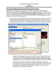
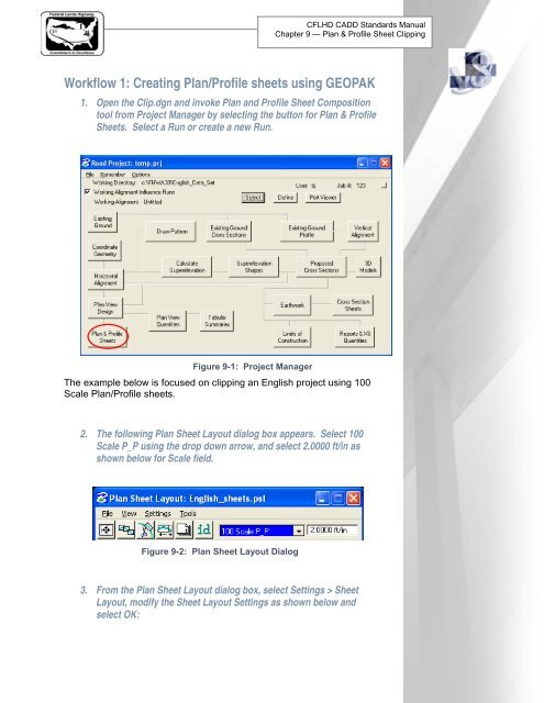
CFLHD CADD Standards Manual<strong>Chapter</strong> 9 — Plan & Profile Sheet ClippingWorkflow 1: Creating Plan/Profile sheets using <strong>GEOPAK</strong>1. Open the Clip.dgn and invoke Plan and Profile Sheet Compositiontool from Project Manager by selecting the button for Plan & Profile<strong>Sheets</strong>. Select a Run or create a new Run.Figure 9-1: Project ManagerThe example below is focused on clipping an English project using 100Scale Plan/Profile sheets.2. The following Plan Sheet Layout dialog box appears. Select 100Scale P_P using the drop down arrow, and select 2.0000 ft/in asshown below for Scale field.Figure 9-2: Plan Sheet Layout Dialog3. From the Plan Sheet Layout dialog box, select Settings > SheetLayout, modify the Sheet Layout Settings as shown below andselect OK:
CFLHD CADD Standards Manual<strong>Chapter</strong> 9 — Plan & Profile Sheet ClippingFigure 9-3: Sheet Layout Settings4. Invoke the Sheet Composition dialog by clicking on the SheetComposition icon from the Plan Sheet Layout dialog as shownbelow:Figure 9-4: Plan Sheet Layout Dialog5. Modify the Sheet Composition dialog box as shown below:
CFLHD CADD Standards Manual<strong>Chapter</strong> 9 — Plan & Profile Sheet ClippingFigure 9-5: Sheet CompositionThe above sheet composition dialog setting shows "sheet style" for 100Scale P_P Sheet. Sheet styles have been created for English andMetric projects. Click HERE for other sheet style settings located at theend of this documentation.6. Invoke the Layout <strong>Sheets</strong> tools by selecting the Layout <strong>Sheets</strong> iconfrom the Plan Sheet Layout dialog as shown below:Figure 9-6: Plan Sheet Layout Dialog
CFLHD CADD Standards Manual<strong>Chapter</strong> 9 — Plan & Profile Sheet ClippingFigure 9-7: Layout Settings7. Select Multiple <strong>Sheets</strong> from the dialog box and Select the GPK fileby keying it into the “Job:” box, or by browsing using the file openicon.8. To populate the Plan Port Data dialog box, double click along therow for Port 1 in the Layout Settings dialog box and the followingdialog box will be invoked.Figure 9-8: Plan Port Data9. Select the correct Chain and the appropriate Plan Motif file. SelectOK. If the Motif File has not been created, create Motif files usingthe Create Motif File icon as shown below:Figure 9-9: Plan Port Data - Create Motif FileMotif file should be created from a 2D seed file. After creating the Motiffile, make sure to attach the required reference files.
CFLHD CADD Standards Manual<strong>Chapter</strong> 9 — Plan & Profile Sheet ClippingTo create Double Plan <strong>Sheets</strong> (plan/plan), attach Plan Motif File to Port1 and 2.10. To populate the Profile Port Data dialog box, double click along therow for Port 2 in the Layout Settings dialog box and the followingdialog box will be invoked.Figure 9-10: Profile Layout11. If a profile cell exists for the file that is referenced to the Clip.dgnfile, then select on Identify cell, place data point on the profile celland accept. Profile Data dialog fields can be populated using thismethod, or manually enter in the required information.12. Select the appropriate Profile Motif file. Select OK. If the Motif filehas not been created, create Motif files using a 2D seed file asoutlined in step 9.13. <strong>GEOPAK</strong> will calculate the number of sheets to layout. Number ofsheets calculated will be placed on the button at the bottom rightof the Layout Settings dialog box. Use the “Extend” distance fieldto shift the clipping shapes ahead or back a given distance frombegin and end stations. If the number of sheets is acceptable,
CFLHD CADD Standards Manual<strong>Chapter</strong> 9 — Plan & Profile Sheet Clippingpress the Layout # <strong>Sheets</strong> button and <strong>GEOPAK</strong> will draw clippingshapes into the drawing.Figure 9-11: Layout SettingsIn order for the data to be clipped correctly, use the Sheet LayoutModify Tools. Two most common types of modification supported aresliding the sheets and modifying the drawing area. The drawing areacannot be increased in Length (Horizontal) or Height (Vertical) toexceed the drawing area setup in the sheet library.14. For extremely curved chains and steep vertical curves it may benecessary to modify the clipping shapes. To invoke the Modifytools, use the Modify <strong>Sheets</strong> icon from the Plan Sheet Layoutdialog as shown below:Figure 9-12: Plan Sheet Layout Dialog
CFLHD CADD Standards Manual<strong>Chapter</strong> 9 — Plan & Profile Sheet ClippingFigure 9-13: Modify Sheet Layout-Plan15. Use the drop down arrow to select the clipping shape to bemodified from the list or Identify the clipping shape by clicking onthe ID button and then data pointing the clipping shape.Figure 9-14: Modify Sheet Layout-ProfileNOTE: The application is intelligent enough to knowwhether a Plan clipping shape or Profile clippingshape has been identified. When a Profile clippingshape is identified, the "Sheet Chord Offset" fieldchanges to "Bottom Elevation", (as shown above).When modifying the vertical position of a Profileclipping shape, toggle "Bottom Elevation" ON, typein the desired "bottom of the shape" elevation, orpress Dynamic and move the shape up or down.Drawing area cannot be increased horizontally orvertically to exceed the drawing area setup in theSheet Library.
CFLHD CADD Standards Manual<strong>Chapter</strong> 9 — Plan & Profile Sheet Clipping16. Use the Sheet Number Manager tool to number sheet to CFLstandards. To invoke the Sheet Number Manager tool, use theSheet Number Manager icon from the Plan Sheet Layout dialog asshown below:Figure 9-15: Plan Sheet Layout DialogFigure 9-16: Sheet Number Manager17. To select all rows, click anywhere on row one, hold down the shiftkey and click a second time anywhere on the last row. Once rowsare selected, select the Edit Sheet Number icon as shown above.18. The Edit Sheet Number dialog box will appear, complete as shownbelow and select OK. Dialog box values correspond to CFLspecific sheet numbering schemes. Use “C” for main plan andprofile sheets or “D” for minor roads. The examples below, thesheets are numbered in sequence beginning with D1.
CFLHD CADD Standards Manual<strong>Chapter</strong> 9 — Plan & Profile Sheet ClippingFigure 9-17: Edit Sheet Number<strong>19</strong>. Upon Selecting OK, Sheet numbers will change from 1 to D1 in theSheet Number Manager dialog box.Figure 9-18: Sheet Number Manager20. To Invoke the Clip <strong>Sheets</strong> tool, Select the Clip <strong>Sheets</strong> icon from thePlan Sheet Layout dialog as shown below:Figure 9-<strong>19</strong>: Plan Sheet Layout Dialog
CFLHD CADD Standards Manual<strong>Chapter</strong> 9 — Plan & Profile Sheet ClippingFigure 9-20: Clip <strong>Sheets</strong>21. In the Clip <strong>Sheets</strong> dialog box, select the directory for the output fileand type in the Sheet Name Prefix. Sheet name prefix shouldfollow the naming convention set in <strong>Chapter</strong> 3 of the CFL CADDstandards Manual.NOTE: The software appends the beginning sheetnumber to the "Sheet Name Prefix". You most likelywill have to rename this (or these) file(s) later.22. Select Orientation to Rotate View for Plan & Profile sheets andSingle Plan sheets. Select Orientation to Rotate Reference forDouble Plans sheets and Profile sheets. Sheet Cell is rotated andmoved into correct position with plan reference file data whenorientation is set to Rotate View. Reference file data is rotated andmoved into correct position with each of the sheet cells whenorientation is set to Rotate Reference.
CFLHD CADD Standards Manual<strong>Chapter</strong> 9 — Plan & Profile Sheet Clipping23. Select Sheet per File to 1. CFLHD policy is to create one sheet perfile.24. Select the Sheet Range required from the pick list using the dropdown arrows.25. Enter Labels and Annotation. Complete Clip <strong>Sheets</strong> dialog asshown below. Select Process <strong>Sheets</strong>.Figure 9-21: Clip <strong>Sheets</strong>Since the CFL reference sheet cell drawing is write protected. Thefollowing dialog box below will appear. Just click OK.