1935-1940 Car - Mustang II - Front End Kit - Total Cost Involved
1935-1940 Car - Mustang II - Front End Kit - Total Cost Involved
1935-1940 Car - Mustang II - Front End Kit - Total Cost Involved
- No tags were found...

Create successful ePaper yourself
Turn your PDF publications into a flip-book with our unique Google optimized e-Paper software.
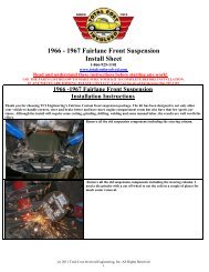
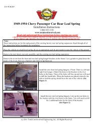
Installing the lower control arms:*NOTE* The acorn side of the 5/8” shaft faces forward.The arrows in the picture denote where the washersare used. There is no washer placed against the frontside of the cross member. There are only 3 washersused per side of the vehicle. Install the 5/8” full nylocknut on the back side of the shaft and torque to 75 ft.Ibs.*NOTE* Driver side control arm is picturedPage 4 of 10(c) 2012 <strong>Total</strong> <strong>Cost</strong> <strong>Involved</strong> Engineering, Inc. All Rights Reserved.
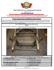
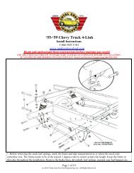
1. (Image A) With the vehicle securely positioned onjack stands remove the grease fitting on the lowerball joint. Install the coil spring with the flat groundside up in the spring pocket and the pig tail endinserted onto the notched portion on the lower a-arm. Use a long screwdriver or flat bar insertedabove the last coil and hooked through the coilpocket to hold the spring from coming out as youjack up the a-arm.2. (Image B) Position the floor jack under the lowera-arm as shown with a clean towel protecting thefinish.3. (Image C) Hook the ratcheting tie down to the front ofthe floor jack cross bar, then go up and over the uppera-arm mounting bracket. With the other end of the tiedown hooked to the other side of the jack’s crossbar.This keeps the frame from going up as you raise thea-arm.4. (Image D) Slowly raise the jack until it is safe toremove the large screwdriver holding the spring inplace. Keep raising the jack until the lower a-arm ishigh enough to fit the shock absorber into place.5. (Image F) Install the shock through the bottom of thelower a-arm with the shock stem going through themounting hole in the upper hat. Align the lower shocksleeve with the shock bosses on the lower a-arm andinstall the 7/16” shock bolt and tightenNote: If you have difficulty with the sleeve fitting betweenthe bosses lightly sand the ends of the sleeve.6. (Image E) Install the cup washers, bushings and nut ontop of the shock stem and tighten. <strong>Car</strong>efully lower the jackand remove the ratchet tie down. Re-install your ball jointgrease fittings. (Image G) This is what your installedspring will look like.The spring that comes with the kit is a 300 lb. per inchrate and is identified with a green dot on the flat end.Page 7 of 10(c) 2012 <strong>Total</strong> <strong>Cost</strong> <strong>Involved</strong> Engineering, Inc. All Rights Reserved.
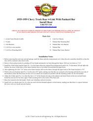
Installing the upper control arms:Use three of the provided .090” thick washersbetween the tower and the control arm shaft on eachbolt. The rest can be placed under the head of eachbolt and under the lock nut. These spacers may needto be moved around when final alignment isperformed. Once all the hardware is in place goahead and set the bolts in the center of alignmentslots and tighten down.The slotted arm mount holes will make it easy to addin extra positive caster for power rack applications.Installing the spindle assemblies:Place the spindle onto the lower ball joint with thesteering arm facing forward with the large I/D tie rodend taper facing down.(The tie rod end goes up intothe spindle)Place the ball joint washer first and then the castlenut. Torque the lower ball joint to 90 ft. lbs andinstall the cotter pin. The lower ball joint is a MOOGK719Pull the upper control arm down onto the spindle.Place the ball joint washer first and then the castlenut. Torque the lower ball joint to 70 ft. lbs andinstall the cotter pin. The upper ball joint is a MOOGK772*NOTE* Caliper Fittings:GM Calipers = 10mm x 1.5Wilwood Calipers = 1/8” NPTCentering the rack assembly:The rack needs to be centered to allow equalsteering left to right. On a bench, turn the pinion outto lock one way. Measure from a convenient point tothe end of the inner tie rod. (This rack was 17 ¾).Turn the pinion of the opposite lock position andmeasure from the same point to the end of the sametie rod (11 ¾). 17 ¾ minus 11 ¾ = 6. Divided by 2 =3 Add that number to the smallest measurement (11¾” + 3” = 14 ¾”) and turn the pinion back till you getthat measurement and your rack is centered.Page 8 of 10(c) 2012 <strong>Total</strong> <strong>Cost</strong> <strong>Involved</strong> Engineering, Inc. All Rights Reserved.
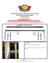
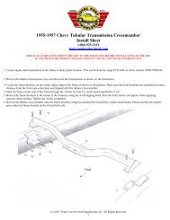
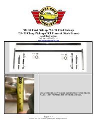
Installing the rack and pinion:Place the rack on the cross member brackets asshown. Use the supplied 5/8” hardware to fasten itinto place. The picture shows a power rack thatrequires a 5/8” spacer between the rack and themounting brackets. A manual rack bolts directly tothe mounting brackets not needing these spacers.Torque bolts to 90 ft. lbs*NOTE* Power Rack & Pinion fittings:9/16”-18 Pressure side & 5/8”-18 Return sideInstall the jam nut and outer tie rod end onto bothsides of the rack. With the rotors pointing straightahead(0 toe) install the tie rod ends into the bottomof the steering arm.Torque the tie rod end to 60 ft. lbs. and install thecotter pin.*NOTE* Rack & Pinion output shaft:Manual rack = 9/16”-26 splinePower rack = ¾”-36 SplineInstalling the anti-sway bar:Slide the lock ring collar over the bar on each sidefirst. The split bushings go over the bar and then thealuminum blocks slide on over the bushings.The anti-sway bar mounts to the rear of the crossmember below the lower control arm pins. Use thesupplied hardware to install the aluminum blocksonto the cross member. Torque to 35 ft lbs.Center the anti-sway bar and lock down the setscrews against the bushings.Page 9 of 10(c) 2012 <strong>Total</strong> <strong>Cost</strong> <strong>Involved</strong> Engineering, Inc. All Rights Reserved.
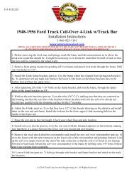
The sway bar routes from behind the cross memberunder the control arms and hooks up to the front ofthe control arms. Use the supplied hardware to installthe heim joints with the male on the bottom.*NOTE* You can adjust the preload(or lack thereof)once the vehicle is ready to be driven. Disconnectone heim, place driver in the driver’s seat, adjust theloose heim until it goes onto the anti-sway bar withzero load.Alignment specificationsCaster: Power rack 4-6 degrees positiveManual rack 2-4 degrees positiveCamber: 0 DegreeToe-in: 1/32 to 1/16 inchAfter 500-1000 miles the front springs will begin tobreak in. The lower control arms should be level tothe ground or within a degree or two. You can nowperform the final alignment. If the vehicle is still toohigh after 1000 miles it may be necessary to cutsome of the coil off. Never cut more than a ¼ coil offat a time.AXLE STUD SIZES:4.5” Bolt circle rotors = ½”x20(’75-’80 Ford Granada)4.75” Bolt circle rotors = 12mmx1.5(’82-’87 Camaro)ALL Wilwood hubs = 7/16”x20No returns or exchanges without an RMA#.Packages must be inspected upon receipt & be reported within 10 days.If you are missing parts from your kit, TCI Engineering will send the missing parts via FedEx or U.S. mail ground.Returned packages are subject to inspection before replacement/refund is given(Some items will be subject to a 15% restocking fee)Thank you for your business!Page 10 of 10(c) 2012 <strong>Total</strong> <strong>Cost</strong> <strong>Involved</strong> Engineering, Inc. All Rights Reserved.