0827- SIGI-271 Break Glass Call Point - Netwell
0827- SIGI-271 Break Glass Call Point - Netwell
0827- SIGI-271 Break Glass Call Point - Netwell
- No tags were found...

You also want an ePaper? Increase the reach of your titles
YUMPU automatically turns print PDFs into web optimized ePapers that Google loves.
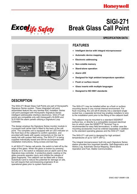
S Y S T E M<strong>SIGI</strong>-<strong>271</strong><strong>Break</strong> <strong>Glass</strong> <strong>Call</strong> <strong>Point</strong>SPECIFICATION DATAFEATURES• Intelligent device with integral microprocessor• Automatic device mapping• Electronic addressing• Non-volatile memory• Stand-alone operation• Alarm LED• Designed for high ambient temperature operation• Flush or surface mount• <strong>Glass</strong> inserts with multiple languages• Designed to ISO 9001 standardsDESCRIPTIONThe <strong>SIGI</strong>-<strong>271</strong> <strong>Break</strong> <strong>Glass</strong> <strong>Call</strong> <strong>Point</strong>s are part of Honeywell'sSignature Series system. These integrated call pointassemblies feature the very familiar KAC Installers’Seriescall point packaged with Honeywell’s Signature Seriesintelligent addressable interface electronics. <strong>SIGI</strong>-<strong>271</strong>callpoints are compatible only with Honeywell’s XLS200 andXLS1000 fire alarm panels utilizing a Signature LoopController.The design employs the Signature Series monitor module ina purpose built carrier that is fitted to the back of the callpoint. The complete unit is equipped with an LED indicator onthe front face of the callpoint to confirm operation, andprovided with leads with spade connectors on the rear toeasily link with system field wiring. The <strong>SIGI</strong>-<strong>271</strong> is beingsupplied individually boxed and will be accompanied withinstallation instructions, fixing screws and test key.In all <strong>SIGI</strong>-<strong>271</strong> Series call points, the switch is held off by theedge of the glass. When the glass is broken by pressingdirectly on it, the switch is released and an alarm sent to theSignature loop controller. A protective plastic coating on theglass prevents operator injury and inhibits the release ofglass fragments. The callpoint can be fitted with a <strong>Glass</strong>Substitute Card to reduce the potential for damage on site,but will require that commissioning engineers fit anoperational glass prior to system hand-over.The <strong>SIGI</strong>-<strong>271</strong> may be installed either as a flush or surfacemounting device in any normal internal environment. Forflush mounting, the unit will fit directly into a standard singlesocket box; a separate terminal tray enables installers to wireto the installation point prior to the fitting of the callpoint itself.The callpoint may be mounted to a standard SSDSR3Tsurface box, or directly to a compatible recessed electricalbox (in which case the SSDETT-P Terminal Tray isrecommended for easy field termination). In either case themounting accessories must be ordered separately in additionto the standard operating glasses and the <strong>SIGI</strong>-<strong>271</strong> itself.The <strong>SIGI</strong>-<strong>271</strong> call point is designed for high ambienttemperatures of up to 120°F (49°C).The integral microprocessor built into each Signature Seriesstation provides four important benefits: Self-diagnostics andHistory Log, Automatic Device Mapping, Stand-aloneOperation and Fast, Stable Communication.EN0C-<strong>0827</strong> 0599R1-OB
<strong>SIGI</strong>-<strong>271</strong> BREAK GLASS CALL POINTSelf-Diagnostics and History Log:Each Signature Series manual call point constantly runs selfchecksto provide important maintenance information. Theresults of the self-check are automatically updated andpermanently stored in the call point's non-volatile memory.This information is accessible for review any time at thecontrol panel, PC, or by using the SIGA-PRO SignatureProgram/Service Tool.The information stored in the call point's memory includes:- <strong>Call</strong> point serial number, address, and type code.- Date of manufacture, hours of operation, and lastmaintenance date.- Number of recorded troubles, alarms, and time anddate of last alarm.- Up to 24 possible trouble codes which can be used tospecifically diagnose faults.Automatic Device Mapping:The Signature loop controller learns where each device'sserial number address is installed relative to other devices onthe circuit. The loop controller keeps a "map" of the SignatureSeries devices connected to it.Signature Series Data Entry Program also uses the mappingfeature. With interactive menus and graphic support, thewired circuits between each device can be determined.Layout or "as-built" drawing information showing thebranches (T-taps), device types and their address are storedon disk for printing hard copy. This takes the mystery" out ofthe installation. The preparation of "as-built" drawings is fastand efficient. Device mapping allows the Signature loopcontroller to discover:- Unexpected additional device addresses.- Missing device addresses.- Changes to the wiring in the circuit.Stand-alone Operation:A decentralized alarm decision by the call point isguaranteed. On-board intelligence permits the call point tooperate in stand-alone mode. If loop controller CPUcommunications fail for more than 4 seconds, all devices onthat circuit go into stand-alone mode. The circuit acts like aconventional alarm receiving circuit. Each call point on theloop will still transmit an alarm if its operating lever is pulled.Fast Stable Communication:Built-in intelligence means less information needs to be sentbetween the call point and the loop controller. Other thanregular supervisory polling response, the call point onlyneeds to communicate with the loop controller when it hassomething new to report. This provides very fast controlpanel response time and allows a lower baud rate (speed) tobe used for communication on the loop. The lower baud rateoffers several advantages including:- Less sensitivity to circuit wire characteristics.- Less sensitivity to noise glitches on the cable.- Less emitted noise from the analog wiring.- Twisted or shielded wiring is not required.Fig.1: Complete Assembly with SSDSR3T BackboxElectronic Addressing:The loop controller electronically addresses each call point,saving valuable time during system commissioning. Settingcomplicated switches or dials is not required. Each call pointhas its own serial number stored in its "on-board memory".The loop controller identifies each device on the loop andassigns a "soft" address to each serial number. If desired, thecall points can be addressed using the SIGA-PRO SignatureProgram/ Service Tool.Alarm LED:A large red LED on the front of the call point provides visualindication of normal and alarm conditions. A flashing LEDmeans the call point is in “alarm” state. A steady-on LEDshows alarm state in “stand-alone” mode.Quality and Reliability:Honeywell fire alarm call points are manufactured in NorthAmerica to strict international ISO 9001 standards. Allelectronics utilize surface mount technology (SMT) forsmaller size and greater immunity to RF noise. A conformalcoating is used for humidity and corrosion resistance.Compatibility:Signature Series call points are compatible only withHoneywell’s XLS200 and XLS1000 fire alarm panels with aSignature Loop Controller.EN0C-<strong>0827</strong> 0599R1-OB 2
Application Notes:The operating characteristics of the fire alarm call points aredetermined by their sub-type code or "Personality Code".NORMALLY-OPEN ALARM - LATCHING (Personality code 1)is assigned by the factory; no user configuration is required.The device is configured for Class B IDC operation. AnALARM signal is sent to the loop controller when the callpoint is operated (i.e. when the glass is broken). The alarmcondition is latched the call point.<strong>SIGI</strong>-<strong>271</strong> BREAK GLASS CALL POINTNOTE: This module will not operate without electrical power.As fires frequently cause power interruption, wesuggest you discuss further safeguards with yourfire protection specialist.Testing and Maintenance:To test the call point simply insert the special test key(provided with every unit); the glass drops and the switchcloses. Removing the key restores the call point to normal.The call point's automatic self-diagnosis identifies when it isdefective and causes a trouble message. The user-friendlymaintenance program shows the current state of eachSignature series device and other pertinent messages.Single devices may be deactivated temporarily, from thecontrol panel. Availability of some maintenance features isdependent on the fire alarm system used.Fig.2: SSDSR3T Flush Mount BackboxScheduled maintenance (regular or scheduled) for propersystem operation should be planned according to localcodes.Installation and Mounting:The Signature Series fire alarm call points flush mount toEuropean General Purpose Outlet Boxes using the SSDETT-P European Terminal Tray. Surface mounting requires theSSDSR3T backbox.Honeywell recommends that these call points be installedaccording to the latest recognized edition of national andlocal codes.Fig.3: SSDETT-P European Terminal TrayMountingScrewsBREAK GLASSBACK PANELCompatible Electrical BoxSSDSR3T SurfaceBox ShownFRONT PLATETEST KEYLoop WiringFig.4:Typical Assembly3 EN0C-<strong>0827</strong> 0599R1-OB
<strong>SIGI</strong>-<strong>271</strong> BREAK GLASS CALL POINTSPECIFICATIONSModels:<strong>SIGI</strong>-<strong>271</strong>: Intelligent call point, English markingsAddressing Requirements:uses 1 module addressType Code:Factory setOperating Voltage:15.2 to 19.95V dc (19V dc nominal)Operating Current:Standby: 250µAActivated: 400µALED Operation:On-board red LED: Flashes when in alarmGlows steady when in “stand-alone” alarm modeCompatibility:Use with Signature Loop ControllerConstruction and Finish:Thermoplastic, red with black markingsMounting:Surface mounted on wall using SSDSR3T surfacemounting box or flush mounted to compatible electricalboxes. However it is advised that the Terminal Tray(SSDETT-P) is used to effectively terminate field wiringto the callpoint.Dimensions in Inches (Millimeters):3-3/8 in. (86mm) Height3-3/8 in. (86mm) Width25/32 in. (20mm) Depth (when flush mounted)1-1/2 in. (38mm) Depth (when mounted on SSDSR3T)Shipping Weight:150 grams (89 x 90 x 35mm carton box)Environmental Limits:Operating Temperature: 32° to 120°F (0° to 49°C)Storage Temperature: -4° to 140°F (-20° to 60°C)Humidity: 0 to 93% rhAccessories:SSDSR3T Surface Mounting BackboxSSDETT-P Terminal TraySSDE-G/10 English <strong>Break</strong> <strong>Glass</strong>es (Pack of 10)KG-1/xx/ Local language <strong>Break</strong> <strong>Glass</strong>esKG-1/25/: Pack of 25KG-1/50/: Pack of 50for available language options see the list belowAvailable languages (Single and double) :ArabicArabic/EnglishAfrikaans/EnglishBelgianEnglish/ChineseDanishDutchEnglish/DutchEnglishEnglish/FrenchGerman/FrenchGermanGreekHebrew/EnglishHungarianEnglish/HungarianIcelandicItalianNorwegianNorwegian/EnglishPortugueseRussianEnglish/SpanishSwedishThai/EnglishEnglish/TurkishWelsh/EnglishApprovals:CE MarkedComfort from ExperienceHome and Building Control Home & Building Control European Centre of ExcellenceHoneywell Inc. Honeywell GmbH Fire SolutionsHoneywell Plaza Honeywellstrasse Lovelace Road, Southern Industrial AreaP.O. Box 524 63477 Maintal 1 Bracknell, Berkshire, RG12 8WDMinneapolis MN 55408-0524 Germany United KingdomEN0C-<strong>0827</strong> 0599R1-OB 4