

Simulation of Soil Nail's Dynamic Pullout Response.pdf - Plaxis
Simulation of Soil Nail's Dynamic Pullout Response.pdf - Plaxis
Simulation of Soil Nail's Dynamic Pullout Response.pdf - Plaxis
- No tags were found...

Create successful ePaper yourself
Turn your PDF publications into a flip-book with our unique Google optimized e-Paper software.
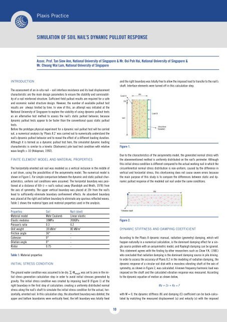
<strong>Plaxis</strong> PracticeSIMULATION OF SOIL NAIL’S DYNAMIC PULLOUT RESPONSEAssoc. Pr<strong>of</strong>. Tan Siew Ann, National University <strong>of</strong> Singapore & Mr. Ooi Poh Hai, National University <strong>of</strong> Singapore &Mr. Cheang Wai Lum, National University <strong>of</strong> SingaporeINTRODUCTIONThe assessment <strong>of</strong> an in-situ nail – soil interface resistance and its load displacementcharacteristic are the main design parameters to ensure the stability and serviceability<strong>of</strong> a nail reinforced structure. Sufficient field pullout results are required for a safeand economic nailed structure design. However, the number <strong>of</strong> available pullout testresults are always limited by time. In view <strong>of</strong> this, an attempt was initiated at theNational University <strong>of</strong> Singapore to explore the viability <strong>of</strong> using dynamic pullout testsas an alternative test method to assess the nail’s static pullout behavior, becausedynamic pullout tests appear to be faster than the conventional quasi static pullouttests.Before the prototype physical experiment for a dynamic nail pullout test will be carriedout, a numerical analysis by ‘<strong>Plaxis</strong> 8.2’ was carried out to numerically understand thenail’s dynamic pullout behavior and to reveal the effect <strong>of</strong> a different loading duration.Although it is termed as a dynamic pullout test here, the simulated dynamic loadingcharacteristic is similar to a kinetic (Statnamic) pile load test condition with relativewave length > 10 (Holeyman, 1992).FINITE ELEMENT MODEL AND MATERIAL PROPERTIESThe horizontally oriented soil nail was modeled as a vertical inclusion in the middle <strong>of</strong>a soil drum, using the possibilities <strong>of</strong> the axisymmetry model. The numerical model isshown in Figure 1. For simple comparison between the dynamic and static pullout characteristics,uniform soil conditions were assumed. The horizontal boundary was positionedat a distance <strong>of</strong> 60r (r = nail’s radius) away (Randolph and Wroth, 1978) fromthe axis <strong>of</strong> symmetry. The upper vertical boundary was placed at 20r from the nail’shead to sufficiently eliminate boundary confinement effects. An absorbent boundarywas placed at the right and bottom boundary to eliminate any spurious reflected waves.Table 1 shows the material types and material properties used in the analysis.Properties <strong>Soil</strong> Nail (steel)Material model Mohr Coulomb Linear elasticElastic modulus 10MPa 200GPaPoisson’s ratio 0.3 0.2Unit weight 18 kN/m 3 80 kN/m 3Friction angle 36° -Cohesion 0° -Dilation angle 0° -Rinter 0.75 -Table 1: Material propertiesINITIAL STRESS CONDITIONThe ground water condition was assumed to be dry. ∑-M weight was set to zero in the initialstress generation calculation step in order to avoid initial stresses generated bygravity. The initial stress condition was created by imposing load B (Figure 1) at theright boundary in the first step <strong>of</strong> calculation; creating a uniformly distributed normalstress along the nail’s shaft to simulate the initial stress condition for the actual, horizontally,oriented nail. In this calculation step, the absorbent boundary was deleted, theupper and bottom boundaries were vertically fixed, the left boundary was totally fixedand the right boundary was totally free to allow the imposed load to transfer to the nail’sshaft. Interface elements were turned <strong>of</strong>f in this calculation step.Figure 1.Due to the characteristics <strong>of</strong> the axisymmetry model, the generated normal stress withthe abovementioned method is uniformly distributed on the nail’s perimeter. Althoughthis initial stress condition is different compared to the actual working nail in which thecircumferential normal stress distribution is non-uniform, caused by the difference invertical and horizontal stress, this shortcoming does not cause severe errors becausethe main purpose <strong>of</strong> this study is to compare the differences between static and dynamicpullout response <strong>of</strong> the modeled soil nail under the same conditions.Figure 2.DYNAMIC STIFFNESS AND DAMPING COEFFICIENTAccording to the <strong>Plaxis</strong> 8 dynamic manual, radiation (geometry) damping, which willhappen naturally in a numerical calculation, is the dominant damping effect for a singlesource problem with an axisymmetric model, and Rayleigh damping can be ignored.This statement agrees with the finding by other researchers such as Chow Y.K. (1981)who concluded that radiation damping is the dominant damping source in pile driving.In order to assess the accuracy <strong>of</strong> <strong>Plaxis</strong> 8.2 in the modeling <strong>of</strong> radiation damping, thedynamic response <strong>of</strong> a circular soil disk with a massless vibrating shaft at the axis <strong>of</strong>symmetry, as shown in Figure 2, was calculated. A known frequency harmonic load wasimposed on the shaft and the calculated vibration response was measured. Accordingto the dynamic equation <strong>of</strong> motion as shown below,Ma + Cv + Ku = Fwith M = 0, the dynamic stiffness (K) and damping (C) coefficient can be back-calculatedby matching the measured displacement (u) and velocity (v) with the imposed10
harmonic load (F). Figure 3 shows the back-analyzed stiffness and damping coefficientplotted against a dimensionless frequency, a 0 , defined asIt was found that the measured displacement trace is identical for 0 > 1.8, thus 2 isproposed as the optimum a value.a 0 =rϖV sWith r = the shaft’s radius, ϖ = the circular frequency and V s = the soil’s distortionstress velocity.The theoretical value for the stiffness and damping coefficient derived by Novak et al(1978) was also plotted in Figure 3 for comparison. It can be concluded that the stiffnessand damping coefficient simulated by ‘<strong>Plaxis</strong> 8.2’ agree well with the theoreticalvalue.Figure 5.RESULT AND DISCUSSIONFigure 3.ELEMENT SIZE EFFECTFigure 5 shows the load displacement curves calculated by <strong>Plaxis</strong> 8.2 for a stiff nail100mm in diameter and 5m in length loaded by a half sine load with different loadingdurations. All dynamic loading results fall in the kinetic loading condition with a relativewave length > 10. The numerically simulated static load displacement curve is alsoplotted in this figure for comparison. This figure clearly shows that the differencebetween dynamic and static load displacement curves becomes less with longer loadingduration.The effect <strong>of</strong> element size is crucial for dynamic calculations, especially for lumpedmass finite element codes such as <strong>Plaxis</strong>. A model with too large element size adverselyaffects the stress wave propagation. Theoretically, the element size must be as smallas possible but it is impractical to adopt very small elements because it increases thecalculation time dramatically. Deeks and Randolph (1992) have proposed that for accuratesimulation <strong>of</strong> stress propagation, the node spacing for a line element must be atleast 1/12 <strong>of</strong> TL, the length travelled by the rising portion <strong>of</strong> the imposed load in themedium.Figure 6.Figure 6 shows the dynamic soil response curves, which were derived from Figure 5 bysubtracting the inertia effects. The inertia effect was assumed equal to the nail’s totalmass multiplied by the nail’s head acceleration, considering that only the nail’s headacceleration is measurable in actual field tests. The difference between the soilresponse curve and the static pullout curve is now purely due to the radiation dampingeffect. The effect <strong>of</strong> an increase in the stiffness coefficient due to dynamic loading isnegligible as shown in Figure 3.Figure 4.To assess the optimum element size for a 15-node triangular element, the same meshin Figure 2 was utilized by replacing the harmonic load with a half sine load with a certainloading duration. Figure 4 plots the displacement trace measured at a distance <strong>of</strong>0.5m from the imposed load for the mesh with a different α ratio, defined asα =TLAverage Element SizeFigure 7 and Figure 8 show the dynamic soil response and static load displacementcurves for a 15m extensible nail, measured respectively at the nail’s head and the nail’stip. Again kinetic loading conditions were ensured. These figures show that the dynamicsoil response curves are almost similar to the static load displacement curve withinsignificant dynamic effects. This is because a longer loading duration (> 60ms) is requiredto achieve a kinetic loading condition. The dimensionless frequency, a0, for alonger loading duration will be smaller; and the damping coefficient will also be smallerby referring to Figure 3. As an example, for a loading duration <strong>of</strong> 100ms, the a0 isequal to 0.03 and the damping coefficient is close to zero (Figure 3).11
<strong>Plaxis</strong> PracticeWHAT IS THE MECHANICAL IMPACT OFFrans Barends, GeoDelft / Delft University <strong>of</strong> TechnologyWater pressures play a crucial role in the stability <strong>of</strong> dikes and excavations. Stabilityand deformation incorporating the actual local pore pressures is based on:Figure 7.equilibrium: σ ij,j ’ = p ,i (1)and can be obtained by PLAXIS. The pore pressure field is conceived as input, as a conditionedvolume force. How this field is determined? Figure 1 shows a typical canalembankment near Delft in the Netherlands which conducts the excess water pumpedout <strong>of</strong> the lowlands, here almost 4 meter under the canal water level.Figure 8.CONCLUSIONIn this article, the dynamic pullout test <strong>of</strong> a single soil nail was simulated using the<strong>Plaxis</strong> 8.2 dynamic module. At first, the ability <strong>of</strong> ‘<strong>Plaxis</strong> 8.2’ to accurately simulate theradiation damping effect <strong>of</strong> a vibrating shaft with an axisymmetric model was examined,and found to be closely comparable with the theoretical solution. From a series <strong>of</strong>parametric studies on the effect <strong>of</strong> element size, it is recommended that the α ratio (asdefined in this article) should be larger than 2 to ensure the accuracy <strong>of</strong> stress propagationin this lumped mass finite element program.The numerically simulated soil nail’s dynamic pullout behavior has provided convincingresults on the viability <strong>of</strong> a dynamic pullout test to assess the static pullout behavior <strong>of</strong>both stiff and extensible nails. Generally the dynamic pullout response is stiffer thanthe static pullout response, mainly due to the damping effect (radiation damping). Theincrease in loading duration decreases the damping effect, and consequently the dynamicpullout response will be closer to the static pullout response. For the simulatedcase, the radiation damping effect is negligible for loading durations > 100ms.REFERENCESChow, Y.K. <strong>Dynamic</strong> Behavior <strong>of</strong> Piles. PhD Thesis, University <strong>of</strong> Manchester. 1981.Deeks A.J. and M.F. Randolph. Accuracy in Numerical Analysis <strong>of</strong> Pile Driving <strong>Dynamic</strong>s.In 4th Int. Conf. Application <strong>of</strong> Stress Wave Theory to Piles, 1992, the Hague, theNetherlands, pp 85-90.Holeyman, A.E. Keynote lecture: Technol<strong>of</strong>y <strong>of</strong> Pile <strong>Dynamic</strong> Testing. In Proc. 4thApplication <strong>of</strong> Stress Wave Theory to Piles, September 1992, the Hague, theNetherlands, pp 195-215.Novak, M., T. Nogami and F. Aboul-Ella. <strong>Dynamic</strong> <strong>Soil</strong> Reactions for Plane Strain Case.J. Engineering Mechanics Division, ASCE, vol. 104, pp 953-959. 1978.Randolph, M.F. and P. Wroth. Analysis <strong>of</strong> Deformation <strong>of</strong> Vertically Loaded piles. J.Geotechnical Engineering div., vol. 104, pp 1465-1488. 1978Figure 1: Stagnant flow in a canal embankment.The stationary groundwater flow pattern in the geological stratification consisting <strong>of</strong>peat, clay, and sand (top down) can be determined by the porous flow equation:stat. flow: K ij (p ,j + γ z ,j ) ,i = 0 (2)where anisotropy and inhomogeneity are included in the permeability K.Capillarity and infiltration by rain, evaporation or overtopping water determine thedynamics <strong>of</strong> the groundwater table. Then the permeability K is a function <strong>of</strong> the moisturecontent θ. This flow field is described by:unsat. flow: K[θ](p ,i ) ,i + γK[θ] ,z = γθ ,t (3)For example, infiltration on a sloping surface shows a saturated zone on top and a wettingfront propagating vertically, finally reaching the groundwater table underneath(see fig. 2)Saturated groundwater flow including storage effects, like fluid compressibility β isformulated by:compr. flow: K ij (p ,j + γ z ,j ) ,i = nγβ p ,t (4)The so-called elastic storage, related to the compressibility <strong>of</strong> the porous medium: α,can be included in a similar manner:stor. flow: K ij (p ,j + γ z ,j ) ,i = S p ,t (5)12


