VG08 - webadmin1.net
VG08 - webadmin1.net
VG08 - webadmin1.net
- No tags were found...

You also want an ePaper? Increase the reach of your titles
YUMPU automatically turns print PDFs into web optimized ePapers that Google loves.
INSTALLATION, OPERATION &MAINTENANCE MANUALMODEL <strong>VG08</strong>ORBINOX SPAIN Pol.Ind. s/n-20270 ANOETA. Tel:+34 943 698030 Fax:+34 943 653066 e-mail:orbinox@orbinox.comORBINOX CANADA, ORBINOX USA, ORBINOX COMERCIAL, ORBINOX UK, ORBINOX FRANCE, ORBINOX GERMANY,ORBINOX INDIA, ORBINOX CHINA.www.orbinox.com
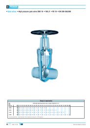
MODEL<strong>VG08</strong>The following table gives the maximum torque values for the valve fixing bolts. Also shown is themaximum depth (T) allowed for the tapped blind boltholes drilled into the valve body.DN 50 65 80 100 125 150 200 250 300 350 400 450 500 600T (mm) 8 8 8,7 8,7 8,7 10,3 12 12 12 15 15 15 22,2 22,2Kg.m 5 5 5 5 7 9 9 15 15 22 22 32 32 32The valve can be mounted in any position with regard to the pipe. However, it is advisable to place itvertically in horizontal pipeline (A) if the installation allows it. (Please consult the technical departmentat Orbinox).With larger diameters (> 300 mm), heavy actuators (pneumatic, electric, etc.), or with the valveinstalled horizontally (B) or at an angle (C) on a horizontal pipeline, the installation will require theconstruction of suitable supports. (See the following diagram and consult the technical departmentat Orbinox).ACCBBC*C*A** For these positions please consult Orbinox.In vertical pipelines, the construction of suitable supports is always required (for further informationplease consult the technical department at Orbinox).Once the valve is installed, test that the flanges have been fastened correctly and that all electricaland/or pneumatic connections have been properly made.Where electric accessories are mounted on the valve (i.e. solenoid valves, electro-pneumaticpositioners, etc.), or is in an ATEX zone, the corresponding earth connections must be made beforeit is put into operation.The operation of automated valves is limited only with fitted gate covers.First, operate the valve with no flow in the pipeline. Then test operation and valve seal with flow.Once performance has been tested, the valve can be put into operation.In an ATEX zone, the continuity between the body of the valve and the pipe must be checked (testin accordance with EN 12266-2 Standard, annex B, points B.2.2.2. and B.2.3.1).It must also be verified that the pipe is connected to earth and that there is electrical conductivitybetween the two pipes (outlet/inlet)..www.orbinox.com2009-1 EDITION<strong>VG08</strong>-4/8
MODEL<strong>VG08</strong>3.- ACTUATORS3.1.- HandwheelTo open the valve, turn the handwheel anticlockwise. To close, turn the handwheel clockwise.3.2.- Bevel gearBevel gear designed for full force below 30Kg.To open the valve, turn the handwheel (11) anticlockwise. To close, turn the handwheelclockwise.3.3.- PneumaticValves are usually supplied with a double acting pneumatic actuator although, upon request,we can supply single-acting actuators. In either case the feed pressure can vary between 3,5and 10 Kg/cm 2 . However, the size of the actuator for each valve has been designed for a feedpressure of 6 Kg/cm 2 .It is essential for a good maintenance of the cylinder that air should be well dried, filtered andlubricated.It is recommended to actuate the cylinder 3-4 times before the start up, once it is installed in thepipeline.3.4.- Electric actuatorDepending on the type or make of the electric actuator, specific instructions (i.e. amanufacturer’s manual) will be supplied.3.5..- HydraulicThe valve is sized based on 150bar hydraulic supply pressure. The cylinder stroke is a fixedlength and does not require any adjustments.Recommendation: actuator maximum manoeuvre speed is 1 second per 25mm of travel.4.- MAINTENANCEThe valve must not undergo any modifications without a previous agreement with ORBINOX.ORBINOX shall not be liable for any damages that may arise due to the use of non original parts orcomponentsTo avoid personal injury or damage to property from the release of process fluid:- Those in charge of handling and maintenance of the valve must be qualified and trained invalve operations.- Use appropriate personal protection equipment (gloves, safety shoes, etc).- Shut off all operating lines to the valve and place a warning sign.- Isolate the valve completely from the process.- Release process pressure.- Drain the process fluid from the valve and insert the open-closed lockout (if the valve hasit).- According to EN 13463-1 (15), during installation and maintenance operations, use handtools (non electric) with Working Allowance.In an ATEX zone, there may be electrostatic charges in the internal parts of the valve. Theseelectrostatic charges, caused by the evacuation of the fluid, may entail a risk of explosion. It is theresponsibility of the user to take extreme precautions to minimize this risk..www.orbinox.com2009-1 EDITION<strong>VG08</strong>-5/8
MODEL<strong>VG08</strong>Safety in an ATEX zone:- The maintenance personnel must be made fully aware of the risks of explosion, and it isadvisable that they receive specific training regarding ATEX.- Should the fluid transported create an internal explosive atmosphere, the user must checkperiodically the correct water-tightness of the installation- Clean the valve periodically to prevent dust accumulation.- Assembly at the end of the line is not allowed.- Avoid repainting the products supplied.The only maintenance required is to change the packing seal (4) and the two rubber sleeves (3) as wellas the use of the grease nipples (7) for regular lubrication.The life of these elements will depend on the working conditions of the valve such as: pressure,temperature, abrasion, chemical action, number of operations, etc.To allow optimal operation, the lower part of the valve, accessible through the splashguard (8) shouldbe cleaned regularly.If the gate is brushed and cleaned regularly, the wear of the sleeves (3) can be minimised.4.1. - Replacement of the packing seal (4):If one or both sleeves (3) have failed, the slurry may injure personnel during this replacement.Then, the valve should be removed from the pipeline before starting the following steps.1) Place the valve in close position and insert the open-closed lockout (if the valve has it).2) Remove the gate guards (for automatically actuated valves only).3) Release the spindle or stem (9) from the gate (2).4) Loosen the screws of the yoke (6), extract the open-closed lockout (if the valve has it) andremove the yoke (without loosing the actuator).5) Loosen the bolts of the gland follower (5) and remove it.6) Remove the gate (2) and the old packing seal (4) and clean the stuffing box.7) Insert the new packing seal (4) lubricated (put silicone-based grease inside of the seal).Radiused edges go in first.8) Insert the gate (2) and tighten the gland follower (5).9) Place the yoke (6) (with the actuator) and screw it.10) Fix the stem (9) to the gate (2).11) Remount the gate guards.12) Carry out some operations with a loaded circuit.4.2.- Replacement of the sealing sleeves (3):1) Remove the valve from the pipeline.2) Remove the sealing sleeves (3).3) Set the gate (2) in the open position.4) Clean within the bodies (1), filling the inner part of the body with silicone based grease.5) Lubricate the new sleeves (3) with the same grease and install them.6) Remount the valve in the pipeline.7) Tighten the flanges.8) Operate the valve a couple of times before leaving it in the position required for the process.4.3. - Lubrication:The VG valve must be lubricated and inspected at least once every 2000 operations, using asilicone based grease for the sleeves.Twice a year, it is recommended to fill up the stem protector (11) halfway with a calcium-basedgrease with the following characteristics: highly water resistant, low ash content, and excellentadherence..www.orbinox.com2009-1 EDITION<strong>VG08</strong>-6/8
MODEL<strong>VG08</strong>After maintenance, and in an ATEX zone, it is obligatory to verify the electrical continuity betweenthe pipe and the different valve components, such as the body, the gate, the supports,... (test inaccordance with EN 12266-2 Standard, annex B, points B.2.2.2. and B.2.3.1).5.- STORAGEStorage recommendations:- Drain valves of any and all liquid.- Indoor storage in a well-ventilated room (to avoid moisture).- Valves should not be exposed to temperatures higher than 30ºC, as some soft seal materials canbe damaged when exposed to higher temperatures (sleeves, packing, …).- If outdoor storage cannot be avoided, cover the valve and protect it from sources of heat or directsunlight.- During the storage, the valve should always be in the open position.- Avoid dirt and/or moisture contamination of the stem.- To prevent contamination in the supply ports of the cylinders: insure actuators have appropriatepipe plugs installed.- The sleeves must be totally relaxed during the storage and without any heavy objects on them.- Prior to start-up, clean the gate and apply grease according point 4.3. of this manual..www.orbinox.com2009-1 EDITION<strong>VG08</strong>-7/8
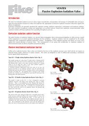
MODEL<strong>VG08</strong>6.- PARTS LIST & DRAWINGS.www.orbinox.com1. – BODY 7. – GREASE NIPPLE2. – GATE 8. – SPLASHGUARD3. – SLEEVES 9. – STEM4. – PACKING SEAL 10. – STEM PROTECTOR5. – GLAND FOLLOWER 11. – BEVEL GEAR6. – YOKE2009-1 EDITION<strong>VG08</strong>-8/8