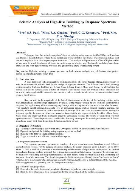
Seismic Analysis of High-Rise Building by Response ... - ijcer
Seismic Analysis of High-Rise Building by Response ... - ijcer
Seismic Analysis of High-Rise Building by Response ... - ijcer
- No tags were found...

You also want an ePaper? Increase the reach of your titles
YUMPU automatically turns print PDFs into web optimized ePapers that Google loves.
<strong>Seismic</strong> <strong>Analysis</strong> Of <strong>High</strong>-<strong>Rise</strong> <strong>Building</strong>…[4] Calculate participation <strong>of</strong> each mode corresponding to the single-degree-<strong>of</strong>-freedom response read from thecurve.[5] Add the effect <strong>of</strong> modes to obtain combined maximum response.[6] Convert the combined maximum response into shears and moments for use in design <strong>of</strong> the structure.Analyze the building for the resulting moments and shears in the same manner as the static loads.In thismethod, natural frequencies and mode shapes are to be obtained <strong>by</strong> a free vibration analysis. The designlateral force at each floor level in each mode <strong>of</strong> vibration is given <strong>by</strong> the equation. The peak shear forceacting in storey i in mode k is given <strong>by</strong> the equation.Q A PWiPkikni1k ni1kiiiW ikikW ( )2The peak storey shear force in storey i due to all modes considered is obtained <strong>by</strong> combining those due to eachmode in accordance with using SRSS combination given <strong>by</strong> equation. So the lateral force at each storey due toall modes considered is calculated <strong>by</strong> the equationF ro<strong>of</strong> = V ro<strong>of</strong>F i = V i – V i + 1In response spectrum method the peak response <strong>of</strong> the structure is calculated from model combination, wherethe following two methods can be used.a) Square Root <strong>of</strong> Sum <strong>of</strong> Square (SRSS) Method (r k)2k = 1where, k = Absolute value <strong>of</strong> quantity in mode kr = Number <strong>of</strong> modes being considered.b) Complete Quadratic Combination Method: rri1 j1 1P1jwhere, i = <strong>Response</strong> quantity in modeP ij = Cross modal coefficientj = <strong>Response</strong> quantity in mode jP j = Cross-modal coefficient82 2(1 ) 4where, = Modal damping ratio in fraction = Frequency ratio = j/ii = Circular Frequency in i th modej = Circular frequency in j th mode2.2 <strong>Response</strong> Spectrum Method <strong>by</strong> using StaadProThis is accurate method <strong>of</strong> analysis. The design lateral force at each floor in each mode is computed <strong>by</strong>STAADPro in accordance with IS: 1893 (Part 1)-2002. The s<strong>of</strong>tware provides result for design values, modalmasses and storey wise base shear. <strong>Response</strong> Spectrum data specification is shown in figure 1.Methodology: The design lateral shear force at each floor in each mode is computed <strong>by</strong> STAAD in accordancewith the IS: 1893 (Part 1) -2002 following equation.Q ik = A k *f ik *P k *W k and V ik = Q ikSTAAD utilizes the following procedure to generate the lateral seismic loads.Z I[1] User provides the value for as factors for input spectrum.2 R[2] Program calculates time periods for first six modes or as specified <strong>by</strong> the user.273273||Issn||2250-3005|| (Online) ||March||2013|| ||www.<strong>ijcer</strong>online.com||
<strong>Seismic</strong> <strong>Analysis</strong> Of <strong>High</strong>-<strong>Rise</strong> <strong>Building</strong>…[3] Program calculates Sa/g for each mode utilizing time period and damping for each mode.[4] The program calculates design horizontal acceleration spectrum A k for different modes.[5] The program then calculates mode participation factor for different modes.[6] The peak lateral seismic force at each floor in each mode is calculated.[7] All response quantities for each mode are calculated.[8] The peak response quantities are then combined as per method (CQC or SRSS or ABS or TEN or CSM) asdefined <strong>by</strong> the user to get the final results.3. <strong>Analysis</strong> <strong>of</strong> <strong>Building</strong> With <strong>Response</strong> Spectrum Method<strong>Seismic</strong> <strong>Analysis</strong> <strong>of</strong> high-rise building having following data is analyzed for different models <strong>of</strong> lateralload resisting systems. Typical plan is shown in figure 2. <strong>Analysis</strong> isFigure:1 <strong>Response</strong> Spectrum data specificationdone <strong>by</strong> taking into account the data form STAADpro. Space frame model is prepared. Member Properties arecolumn size up to 6 th storey 0.45 X 0.60m, column size above 6 th storey 0.30 X 0.45m, beam size 0.23 X 0.30m,shear wall 0.2m, concrete bracing 0.23 X 0.23m, thickness <strong>of</strong> slab 0.1m. Loads considered are floor load, wallload, live load and earthquake load. The grade <strong>of</strong> concrete is M 20 & steel used is Fe 415 .The parametric study for following mentioned models is carried.[1] Bare frame[2] Brace frameCase 1 Bracing at location A in plan- Bracing is centrally located at exterior frame <strong>of</strong> Z direction through outheight.Case 2 Bracing at location B in plan- Bracing is centrally located at exterior frame <strong>of</strong> X direction through outheight.Case 3 Bracing at location A and B in plan- Bracing is centrally located at exterior frame <strong>of</strong> both X and Zdirection through out height.Case 4 Bracing at location C in plan- Bracing is located at exterior frame end corners <strong>of</strong> both X and Z directionthrough out height.3.1 Shear wall frameCase 1 Shear wall at location A in plan- Shear wall is centrally located at exterior frame <strong>of</strong> Z direction throughout height.Case 2 Shear wall at location B in plan- Shear wall is centrally located at exterior frame <strong>of</strong> X direction throughout height.Case 3 Shear wall at location A and B in plan- Shear wall is centrally located at exterior frame <strong>of</strong> both X and Zdirection through out height.Case 4 Shear wall at location C in plan- Shear wall is located at exterior frame end corners <strong>of</strong> both X and Zdirection through out height.For present work response spectrum method as per IS:1893-2002 is carried out for reinforced concrete momentresisting frame having (G+14) storey situated in zone IV. The floor to floor height <strong>of</strong> the building is 3m. Thetotal height <strong>of</strong> building is 45m.Load combinations considered in this analysis are274274||Issn||2250-3005|| (Online) ||March||2013|| ||www.<strong>ijcer</strong>online.com||
<strong>Seismic</strong> <strong>Analysis</strong> Of <strong>High</strong>-<strong>Rise</strong> <strong>Building</strong>…1) 1.5(DL+LL)2) 1.2(DL+LL+EQX)3) 1.2(DL+LL-EQX)4) 1.2(DL+LL+EQZ)5) 1.2(DL+LL-EQZ)6) DL+1.5EQX7) DL-1.5EQX8) DL+1.5EQZ9) DL-1.5EQZFigure 2 Plan <strong>of</strong> building showing location <strong>of</strong> braced frame & shear wall frameDesign Parameters: The design spectrum used is <strong>of</strong> medium soil as per IS 1893 Part I (2002). A responsespectrum is shown in figure 3.Figure 3 <strong>Response</strong> spectrum for soil as per IS 1893 Part I (2002)4. Result and DiscussionThe variation <strong>of</strong> storey drift, base shear, story deflection and time period is evaluated for all thesemodels and compared with response spectrum method.4.1 Variation <strong>of</strong> base shear, story deflection, storey drift and time periodThe parametric study to know base shear, story deflection, storey drift & time period in case <strong>of</strong> allmodels is performed here. The results are shown in table I to IV & in graph 1 to 4 which are listed below. FromTable I and graph 1, it is observed that base shear minimum for case 2 and 3 in both brace frame and shear wallframe. From Table II and graph 2, time period is also less for case 2 and 3 in both brace frame and shear wallframe. As base shear increases time period <strong>of</strong> models decreases and vise versa. <strong>Building</strong> with short time periodtends to suffer higher accelerations but smaller displacement. Therefore, from table III & IV, graph 3 & 4 storydeflections is also minimum for case 2 and 3 in both brace frame and shear wall frame. Story drift i.e. top storydisplacement is also reduced for case 2 and 3 in both brace frame and shear wall frame.275275||Issn||2250-3005|| (Online) ||March||2013|| ||www.<strong>ijcer</strong>online.com||
Scheme Features <strong>of</strong> Reliance Index Fund – Nifty PlanInvestment ObjectiveNature <strong>of</strong> the SchemeBenchmarkProposed Asset AllocationThe primary investment objective <strong>of</strong> the scheme is to replicate thecomposition <strong>of</strong> the NIFTY, with a view to generate returns that arecommensurate with the performance <strong>of</strong> the NIFTY, subject to trackingerrors.An Open Ended Index Linked SchemeS&P CNX NIFTY INDEXEquities & equity related securities covered <strong>by</strong> Nifty - 95% to100%Cash/CBLO/Repo & Reverse Repo & Money Market instruments(CPs,CDs, Tbills, Mibor linked instruments with daily Put/Call options &overnight Interest rate Reset Linked Instruments)but excludingSubscription and Redemption Cash Flow # - 0% to 5%Fund ManagerChoice <strong>of</strong> Plans/OptionsMinimum InvestmentLoad Structure#Subscription Cash Flow is the subscription money in transit before deployment andRedemption Cash Flow is the money kept aside for meeting redemptions.Krishan Daga(a) Growth Plan(1) Growth Option(2) Bonus Option(b) Dividend Plan (Payout Option & Reinvestment Option)(1) Quarterly Dividend Option(2) Half Yearly Dividend Option(3) Annual Dividend OptionRs. 5000 & in multiples <strong>of</strong> Re 1 thereafterEntry Load* : Not ApplicableExit Load :1% <strong>of</strong> the applicable NAV if redeemed or switched out on or beforecompletion <strong>of</strong> 1 year from the date <strong>of</strong> allotment <strong>of</strong> units.There shall be no exit load after completion <strong>of</strong> 1 year from the date <strong>of</strong>allotment <strong>of</strong> units*In accordance with the requirements specified <strong>by</strong> the SEBI circular no. SEBI/IMD/CIRNo.4/168230/09 dated June 30, 2009 no entry load will be charged for purchase /additional purchase / switch-in accepted <strong>by</strong> the Fund with effect from August 01,2009. Similarly, no entry load will be charged with respect to applications forregistrations under systematic investment plans/ systematic transfer plans accepted<strong>by</strong> the Fund with effect from August 01, 2009.DisclaimersThe views expressed herein constitute only the opinions and do not constitute any guidelines or recommendation on any course <strong>of</strong>action to be followed <strong>by</strong> the reader. This information is meant for general reading purposes only and is not meant to serve as apr<strong>of</strong>essional guide for the readers. Certain factual and statistical (both historical and projected) industry and market data and otherinformation was obtained <strong>by</strong> RCAM from independent, third-party sources that it deems to be reliable, some <strong>of</strong> which have beencited above. However, RCAM has not independently verified any <strong>of</strong> such data or other information, or the reasonableness <strong>of</strong> theassumptions upon which such data and other information was based, and there can be no assurance as to the accuracy <strong>of</strong> suchdata and other information. Further, many <strong>of</strong> the statements and assertions contained in these materials reflect the belief <strong>of</strong> RCAM,which belief may be based in whole or in part on such data and other information.The Sponsor, the Investment Manager, the Trustee or any <strong>of</strong> their respective directors, employees, affiliates or representatives donot assume any responsibility for, or warrant the accuracy, completeness, adequacy and reliability <strong>of</strong> such information. Whilst noaction has been solicited based upon the information provided herein, due care has been taken to ensure that the facts are accurateand opinions given are fair and reasonable. This information is not intended to be an <strong>of</strong>fer or solicitation for the purchase or sale <strong>of</strong>5 Product/PN/Ver 1.0/Feb,2012
<strong>Seismic</strong> <strong>Analysis</strong> Of <strong>High</strong>-<strong>Rise</strong> <strong>Building</strong>…Graph 4 Storey drift in mmBrace frameShear wall frameMethodBareframecase 1(bracing atlocation A inplan)case 2(bracingat locationB in plan)case 3(bracingatlocationA & B inplan)Case 4(bracing atlocation Cin plan)case 1(Shearwall atlocation Ain plan)case2(Shearwall atlocationB inplan)case 3(Shearwall atlocationA & B inplan)Case 4(Shear wallat locationC in plan)RSM 272.5 366.92 527.2 612.9 553.9 304.05 495.4 482.9 358Table I Design Base Shear in KNBrace frameShear wall frameMethodBareframecase 1(bracingatlocationA inplan)case 2(bracingat locationB in plan)case 3(bracing atlocation A& B inplan)Case 4(bracingatlocation C inplan)case 1(Shearwall atlocationA inplan)case2(Shearwall atlocation Bin plan)case 3(Shearwall atlocation A& B inplan)Case 4(Shearwall atlocation Cin plan)RSM 1.315 1.319 0.794 0.66 0.68 0.8 0.79 0.66 0.57Table II Time Period in secBrace frameShear wall frameStoryLevelBareframecase 1(bracingatlocationA inplan)case 2(bracingatlocation Bin plan)case 3(bracingatlocationA & B inplan)Case 4(bracingatlocationC inplan)case 1(Shearwall atlocationA inplan)case2(Shearwall atlocationB inplan)case 3(Shearwall atlocationA & B inplan)Case 4(Shearwall atlocationC inplan)1 0.34 0.34 0.23 0.39 0.3 0.35 0.14 0.14 0.092 2.55 2.56 1 0.48 1.06 2.63 0.87 0.87 0.73 5.88 5.9 1.85 1.98 2.05 6.06 1.58 1.57 1.444 9.69 9.73 2.87 3.03 3.32 9.99 2.48 2.45 2.425 13.65 13.71 4.04 4.21 4.71 14.05 3.55 3.51 3.66 17.58 17.64 5.32 5.49 6.24 18.05 4.77 4.72 4.957 21.38 21.46 6.68 6.85 7.86 21.92 6.11 6.05 6.44277||Issn||2250-3005|| (Online) ||March||2013|| ||www.<strong>ijcer</strong>online.com||
<strong>Seismic</strong> <strong>Analysis</strong> Of <strong>High</strong>-<strong>Rise</strong> <strong>Building</strong>…8 25.26 23.35 8.16 8.3 9.61 25.85 7.55 7.48 8.059 28.79 28.89 9.71 9.82 11.47 29.4 9.07 8.99 9.7410 31.98 32.09 11.31 11.4 13.4 32.61 10.64 10.55 11.4911 34.84 34.96 12.92 13 15.39 35.48 12.25 12.15 13.2812 37.34 37.47 14.52 14.6 17.38 37.98 13.88 13.76 15.0813 39.45 39.58 16.09 16.18 19.37 40.06 15.51 15.39 16.8814 41.09 41.23 17.58 17.71 21.33 41.69 17.15 17.02 18.6815 42.25 42.39 19.04 19.2 23.23 42.82 18.78 18.64 20.4616 42.99 43.12 20.38 20.6 25.09 43.51 20.38 20.23 22.19MethodBareframecase 1(bracing atlocation A inplan)Table III Storey deflection in mmBrace framecase 2(bracing atlocation B inplan)case 3(bracingatlocationA & Bin plan)Case 4(bracingatlocationC inplan)case 1(Shearwall atlocationA inplan)Shear wall framecasecase 32(Shea(Shearr wallwall atatlocationlocatioA & B inn B inplan)plan)Case 4(Shearwall atlocation C inplan)RSM 42.99 43.12 20.38 20.6 25.09 43.51 20.38 20.23 22.19Table IV Storey drift (Top storey displacement) in mm5. Conclusions A significant amount <strong>of</strong> decrease in story drift has been observed in case 2 and 3 i.e. lateral stiffness systemis centrally located at exterior frame <strong>of</strong> X direction through out height and lateral stiffness system iscentrally located at exterior frame <strong>of</strong> X & Z direction through out height in both brace frame and shear wallframe compared to other models. Also shear wall models in case 3 gives less storey deflection and storeydrift than bare frame and brace frame.A significant amount <strong>of</strong> decrease in time period <strong>of</strong> model in case 2 and 3 i.e. lateral stiffness system iscentrally located at exterior frame <strong>of</strong> X direction through out height and lateral stiffness system is centrallylocated at exterior frame <strong>of</strong> X & Z direction through out height in both brace frame and shear wall framecompared to other models, therefore displacements in the structure are minimized.<strong>Building</strong> with short time period tends to suffer higher accelerations but smaller displacement. Comparing the top storey drift in the longitudinal direction, it can be seen that it decrease <strong>by</strong> 52.59%,52.08% & 41.63% in case 2, 3 and 4 <strong>of</strong> brace frame as compared to bare frame and it decreases <strong>by</strong> 52.59%,52.94 & 48.38% in case 2, 3 and 4 <strong>of</strong> shear wall frame as compared to bare frame. The models with shearwall located at exterior frame <strong>of</strong> X & Z direction through out height is found most effective in resistinglateral loads because it shows least deflection as compare with other models.A significant amount <strong>of</strong> increase in the lateral stiffness has been observed in all models <strong>of</strong> brace frame andshear wall frame as compared to bare frame.More accurate values <strong>of</strong> response may be obtained for buildings <strong>by</strong> the modal analysis method, usingmodified design response spectra for inelastic analysis.References[1] IS 1893-2002, ‘Indian Standard Criteria <strong>of</strong> practice for Earthquake Resistant Design <strong>of</strong> Structures’,Bureau <strong>of</strong> Indian Standards, New Delhi, India[2] Pankaj Agrawal, Manish Shrikhande, ‘Earthquake Resistant Design <strong>of</strong> Structures’, Prentice Hall IndiaPublication278||Issn||2250-3005|| (Online) ||March||2013|| ||www.<strong>ijcer</strong>online.com||
<strong>Seismic</strong> <strong>Analysis</strong> Of <strong>High</strong>-<strong>Rise</strong> <strong>Building</strong>…[3] Liu Haufeng, Zhao Ning, ‘Study on Tall buildings structure <strong>Analysis</strong>’, Joint international Conference onComputing and decision making in Civil and <strong>Building</strong> Engineering, Montreal, Canada, June 14-16, 2006,pp 4018-4024[4] Bangle S. Taranath, Textbook <strong>of</strong> McGraw Hill International Editions, ‘Structural <strong>Analysis</strong> and Design <strong>of</strong>Tall <strong>Building</strong>s’ 1988, pp 563-569[5] D.-G. Lee & H.S. Kim, ‘Efficient seismic analysis <strong>of</strong> high-rise buildings considering the basements’,NZSEE Conference, 2001, pp 1-9[6] Yongqi Chen, Tiezhu Cao, Liangzhe Ma, and ChaoYing luo, ‘<strong>Seismic</strong> protection system and its economicanalysis on the beijing high-rise building pangu plaza’, The 14 World Conference on EarthquakeEngineering,October 12-17, 2008, Beijing, China[7] Andreas J. Kappos, Alireza Manafpour, ‘<strong>Seismic</strong> design <strong>of</strong> R/C buildings with the aid <strong>of</strong> advancedanalytical techniques’, Engineering Structures 23 (2001), pp 319–332279||Issn||2250-3005|| (Online) ||March||2013|| ||www.<strong>ijcer</strong>online.com||