BM Motor Brake Kit - Rotor UK
BM Motor Brake Kit - Rotor UK
BM Motor Brake Kit - Rotor UK
- No tags were found...

You also want an ePaper? Increase the reach of your titles
YUMPU automatically turns print PDFs into web optimized ePapers that Google loves.
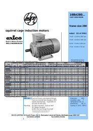
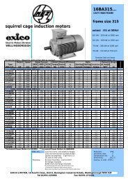
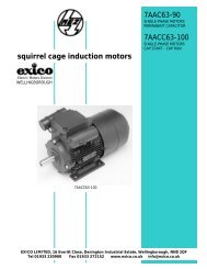
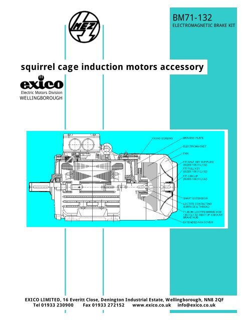
<strong>BM</strong>71-132ELECTROMAGNETIC BRAKE KITsquirrel cage induction motors accessoryElectric <strong>Motor</strong>s DivisionWELLINGBOROUGHEXICO LIMITED, 16 Everitt Close, Denington Industrial Estate, Wellingborough, NN8 2QFTel 01933 230900 Fax 01933 272152 www.exico.co.uk info@exico.co.uk
<strong>Brake</strong>s <strong>BM</strong>...Assembly <strong>Kit</strong> for Three-phase <strong>Motor</strong>sAny standard off-the-shelf Siemens / MEZ electric motor canbe fitted with LENZE brake supplied as an assembly kit. Inorder to be able to fit a <strong>BM</strong> brake to 71, 80 or 90 frameelectric motor you must have an access to a lathe to be ableto drill and tap a hole in the shaft which is not drilled andtapped as standard as well as to modify the NDE shaft in theway described below.FITTING INSTRUCTIONS:A. Dismantling parts from the standard motora) Dismantle motor fan cover by removing the holding screws.c) Dismantle NDE endshield after removing all 4 screws which hold the endshield to the frameThe surfaces under the screw heads are not machined as standard to achieve sufficient planeness in the range of 0 to0.4mm; it is therefore necessary to fit the machined enshield supplied as a part of the brake kit.B. <strong>Brake</strong> fittingB.a Frame Sizes 71, 80, 90:a) Dismantle the front endshield and the rotor from the stator.b) Fit the rotor in a lathe and drill and tap hole “D” in the NDEshaft using the “Drill Size” specified in the table below.c) Drill and tap hole “S” positioned approximately in the middleof the turned-down end of the NDE shaft.Size A B C D S Drill Size71… 2 3 17 M5 M5 4.280… 3 3 20 M6 M6 5.090… 4 4 20 M6 M6 5.0Extra Length<strong>Brake</strong> LE<strong>BM</strong>71 51<strong>BM</strong>80 54<strong>BM</strong>90 75<strong>BM</strong>100 78<strong>BM</strong>112 87<strong>BM</strong>132 106d) Fit the endshiled supplied but do not screw it on. Fit a Grub Screw “S” in the NDE shaft.e) De-grease all contacting surfaces (shaft end, shaft face and shaft extension face)f) Use LOCTITE 603 to fit the supplied <strong>Brake</strong> Hub onto the shaft. The <strong>Brake</strong> Hub keyway to be fitted overthe Grub Screw.B.b Frame Sizes 100, 112, 132 (NDE shaft supplied drilled and tapped as standard):a) Remove fan key and from NDE shaft.b) Fit the endshiled supplied but do not screw it on.c) Replace fan key in NDE shaft with the half-key supplied.d) Heat the toothed <strong>Brake</strong> Hub to the temperature 280° to 300°C and mount it on the NDE shaft end so the faceof the toothed <strong>Brake</strong> Hub is in line with the end of the shaft. If mounted at a lower temperature than 280°Cthe toothed <strong>Brake</strong> Hub would stretch and become unusable!e) Before fitting the shaft extension the fan key must be inserted in its keyway (the larger keyway is for balancingpurposes and must be left without any key).f) De-grease all contacting surfaces (shaft face and shaft extension face)Continuation of FITTING INSTRUCTIONS common for all Frame Sizes:g) Apply LOCTITE 603 on the NDE shaft face and Shaft Extension face and screw the Shaft Extension in.h) Fit the brake itself attached to the steel braking plate by using the 4 socket screws.i) Fit the original fan on the shaft extension (lock it with the circlip - larger motor sizes only).k) Fit the rectifier (supplied) in the terminal box and connect it. Larger terminal boxes are supplied as partof the brake kit for frame sizes 71 and 80.l) Fit the extended fan cover supplied.
LENZE BRAKE HAND RELEASE ASSEMBLY6.01 stirrup6.02 lever6.03 screw6.04 washer6.05 spring6.06 handle6.07 spring washer6.08 washer6.09 boltDimension “S” must be maintainedfor correct function of Hand Release.The Air Gap is to be adjusted to “SL0”AIR GAP ADJUSTMENT<strong>Brake</strong><strong>Kit</strong>SAir GapDiscThicknessNominal SL0 Maximum SL0 MAX TMINmm mm mm mm<strong>BM</strong>71 1 0.2 0.4 4.3<strong>BM</strong>80 1 0.2 0.5 5.3<strong>BM</strong>90 1 0.2 0.5 7.3<strong>BM</strong>100 1.3 0.3 0.5 6.0<strong>BM</strong>112 1.3 0.3 0.8 6.0<strong>BM</strong>132 1.5 0.3 0.8 7.0The Air Gap S L0 is to be measured between the Electromagnet (2) and the Stationary Disc and can be adjusted byturning of the Adjustment Screws (3). Subsequent tightening of the Fixing Screws (1) is necessary.The Air Gap S L0 dimensions can be found in the table above. When adjusting the Air Gap check Thickness of therotating Disc for T MIN .<strong>Brake</strong><strong>Kit</strong>LENZERef.<strong>Brake</strong>Torque Current Input ReactionTime*<strong>Brake</strong>releaseTime*Momentof Inertia[kgm²]SwitchingNoise<strong>BM</strong>71 2LM8 005-2 5Nm 0.10A 20W 17ms 35ms 0.000013 77dB<strong>BM</strong>80 2LM8 010-3 10Nm 0.12A 25W 20ms 50ms 0.000045 74dB<strong>BM</strong>90 2LM8 020-4 20Nm 0.15A 30W 30ms 90ms 0.000160 75dB<strong>BM</strong>100 2LM8 040-5 40Nm 0.20A 40W 40ms 120ms 0.000360 80dB<strong>BM</strong>112 2LM8 060-6 60Nm 0.25A 50W 65ms 150ms 0.000630 77dB<strong>BM</strong>132 2LM8 100-7 100Nm 0.27A 55W 90ms 180ms 0.001500 75dB*The switching time is given for switching on the DC side of the rectifier. If switching on the AC Side of therectifier the time is approximately 6 times longer !The LENZE <strong>Brake</strong>s are single disc brakes with 2 friction surfaces. The brake torque isachieved by springs. The disengagement is electromechanical. The Rotating Disc (3) isshifted on the Toothed Hub (4) mounted on the Shaft (5) and pressed against the frictionsurface of the steel Braking Plate (6) during braking. The movement is actioned byPush Springs (2) through the Stationary Disc (1) and the Electromagnet (7). To disengage the brake aDC voltage must be supplied to the Electromagnet (7). The electromagnetic force then pulls the Stationary Disc(1) towards the Electromagnet (7) enabling the Rotating Disc (3) free rotation.RECTIFIERS - Suitable rectifiers are delivered as a part of the brake kit. The input voltage is230V±10% 50/60Hz, which must be connected to the 2 terminals designated (~). The Electromagnetleads must be connected to (+), (-). The polarity is not essential.All Technical Data and Dimensions given in this Catalogue are subject to change without notice. Always consult Name Plate for technical information.