DCN Next Generation - Bosch
DCN Next Generation - Bosch
DCN Next Generation - Bosch
- No tags were found...

Create successful ePaper yourself
Turn your PDF publications into a flip-book with our unique Google optimized e-Paper software.
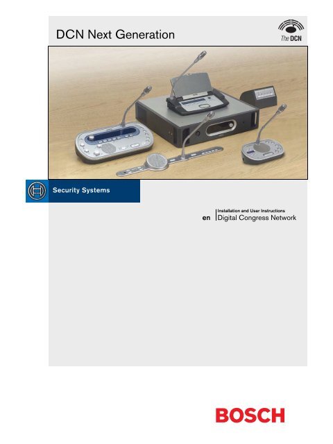
<strong>DCN</strong> <strong>Next</strong> <strong>Generation</strong>enInstallation and User InstructionsDigital Congress Network
<strong>DCN</strong> <strong>Next</strong> <strong>Generation</strong> | Installation and User Instructions | Important Safeguards en | 3Important SafeguardsBefore you install or operate the <strong>DCN</strong> <strong>Next</strong> <strong>Generation</strong>digital congress network, you must read the ImportantSafety Instructions. The Important Safety Instructionsare supplied together with the central control unit.<strong>Bosch</strong> Security Systems | 2005-09 | 9922 141 70524
<strong>DCN</strong> <strong>Next</strong> <strong>Generation</strong> | Installation and User Instructions | Disclaimers en | 4DisclaimersCobraNet is a trademark of Peak Audio — a division ofCirrus Logic, Inc. — in the United States and/or othercountries.<strong>Bosch</strong> Security Systems | 2005-09 | 9922 141 70524
<strong>DCN</strong> <strong>Next</strong> <strong>Generation</strong> | Installation and User Instructions | About this manual en | 5About this manualFunctionThe Installation and User Instructions gives theinstallers and the operators the necessary data to install,configure and operate the <strong>DCN</strong> <strong>Next</strong> <strong>Generation</strong> digitalcongress network.Digital versionThe Installation and User Instructions is available as adigital file (Portable Document File, PDF).When the PDF refers you to a location that containsmore data, you can click the text to go there. The textcontains hyperlinks.Precautions and notesThe Installation and User Instructions uses precautionsand notes. The precaution gives the effect if you do notobey the instructions. These are the types:• NoteA note gives more data.• CautionIf you do not obey the caution, you can causedamage to the equipment.• WarningIf you do not obey the warning, you can causepersonal injury or death.SignsThe Installation and User Instructions shows eachprecaution with a sign. The sign shows the effect if youdo not obey the instruction.PrecautionGeneral sign for cautions and warnings.PrecautionRisk of electric shock.PrecautionRisk of electro-static discharges (refer to thesection ’Electro-static discharges’).The sign that is shown along with a note gives moredata about the note itself.NoteGeneral sign for notes.NoteRefer to another information source.<strong>Bosch</strong> Security Systems | 2005-09 | 9922 141 70524
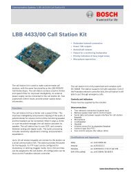
<strong>DCN</strong> <strong>Next</strong> <strong>Generation</strong> | Installation and User Instructions | About this manual en | 6Electro-static dischargesElectro-static discharges can damage electriccomponents. You must take measures to preventelectro-static discharges when you touch PCBs (refer tofigure 1).1 234 5Conversion tablesLength, mass and temperature are in SI units. Refer tothe data below to change SI units to imperial units.table 2: Conversion of units of length1 in = 25.4 mm 1 mm = 0.03937 in1 in = 2.54 cm 1 cm = 0.3937 in1 ft = 0.3048 m 1 m = 3.281 ft1 mi = 1.609 km 1 km = 0.622 mitable 3: Conversion of units of mass1 lb = 0.4536 kg 1 kg = 2.2046 lbtable 4: Conversion of units of pressure1 psi = 68.95 hPa 1 hPa = 0.0145 psiNote1 hPa = 1 mbar.12 11 10 9 8 7 6figure 1: ESD preventiontable 1: ESD preventionNo. Description1 Safety isolating transformer2 Distribution supply box3 Conductive compartment trays4 Electro-static voltage sensor5 Cotton overall6 Conductive floor mat7 Conductive boots/heel grounding protectors8 Conductive stool9 Strap (resistance 0.5 to 1.0 MΩ)10 Common reference point11 Conductive bench top12 Supply groundtable 5: Conversion of units of temperature°F=9--- ⋅ °C + 3255°C = --- ⋅ ( °F – 32)9<strong>Bosch</strong> Security Systems | 2005-09 | 9922 141 70524
<strong>DCN</strong> <strong>Next</strong> <strong>Generation</strong> | Installation and User Instructions | Table of Contents en | 88.1 Introduction ............................................................................................................................................................................ 428.2 Controls, connectors and indicators ............................................................................................................................... 428.3 Internal settings .................................................................................................................................................................... 438.4 Installation .............................................................................................................................................................................. 478.5 External connections ........................................................................................................................................................... 478.6 Configuration menu ............................................................................................................................................................. 539. <strong>DCN</strong>-CCUB Basic Central Control Unit ................................................................................................................................ 629.1 Introduction ............................................................................................................................................................................ 629.2 Controls, connectors and indicators ............................................................................................................................... 629.3 Internal settings .................................................................................................................................................................... 639.4 Installation .............................................................................................................................................................................. 639.5 External connections ........................................................................................................................................................... 639.6 Configuration menu ............................................................................................................................................................. 6510. <strong>DCN</strong> Configuration ..................................................................................................................................................................... 6610.1 Introduction ............................................................................................................................................................................ 6610.2 Initialization ............................................................................................................................................................................. 6610.3 Microphone modes .............................................................................................................................................................. 6710.4 Audio routing modes ........................................................................................................................................................... 6710.5 Attention chimes ................................................................................................................................................................... 7010.6 Erase lists ............................................................................................................................................................................... 7010.7 Floor distribution ................................................................................................................................................................... 7010.8 Intercom .................................................................................................................................................................................. 7011. Camera control ............................................................................................................................................................................. 7211.1 Introduction ............................................................................................................................................................................ 7211.2 Scenarios ............................................................................................................................................................................... 7211.3 Direct camera control without a <strong>DCN</strong> control PC ........................................................................................................ 7211.4 Video switcher without a <strong>DCN</strong> control PC .................................................................................................................... 7411.5 Direct control with a <strong>DCN</strong> control PC ............................................................................................................................. 7611.6 Video switcher with a <strong>DCN</strong> control PC .......................................................................................................................... 7712. <strong>DCN</strong>-EPS Extension Power Supply ........................................................................................................................................ 8012.1 Introduction ............................................................................................................................................................................ 8012.2 Controls, connectors and indicators ............................................................................................................................... 8012.3 Internal settings .................................................................................................................................................................... 8112.4 Installation .............................................................................................................................................................................. 8212.5 External connections ........................................................................................................................................................... 8213. LBB4402/00 Audio Expander .................................................................................................................................................. 8413.1 Introduction ............................................................................................................................................................................ 8413.2 Controls, connectors and indicators ............................................................................................................................... 8413.3 Installation .............................................................................................................................................................................. 8513.4 External connections ........................................................................................................................................................... 8613.5 Configuration menu ............................................................................................................................................................. 9114. PRS-4DEX4 Digital Audio Expander ...................................................................................................................................... 9714.1 Introduction ............................................................................................................................................................................ 9714.2 Controls, connectors and indicators ............................................................................................................................... 9714.3 Installation .............................................................................................................................................................................. 9814.4 External connections ........................................................................................................................................................... 9914.5 Configuration menu ...........................................................................................................................................................10415. LBB4404/00 Cobranet Interface ..........................................................................................................................................110<strong>Bosch</strong> Security Systems | 2005-09 | 9922 141 70524
<strong>DCN</strong> <strong>Next</strong> <strong>Generation</strong> | Installation and User Instructions | Table of Contents en | 915.1 Introduction ..........................................................................................................................................................................11015.2 Controls, connectors and indicators .............................................................................................................................11015.3 Installation ............................................................................................................................................................................11115.4 External connections .........................................................................................................................................................11215.5 Configuration menu ...........................................................................................................................................................11416. CobraNet Discovery ..................................................................................................................................................................12016.1 Introduction ..........................................................................................................................................................................12016.2 Installation ............................................................................................................................................................................12016.3 Start .......................................................................................................................................................................................12016.4 Operation .............................................................................................................................................................................12016.5 Configuration .......................................................................................................................................................................12117. CNConfig ....................................................................................................................................................................................12217.1 Introduction ..........................................................................................................................................................................12217.2 Installation ............................................................................................................................................................................12217.3 Start .......................................................................................................................................................................................12217.4 Operation .............................................................................................................................................................................12217.5 Configuration .......................................................................................................................................................................123Section 3 - Contribution Devices.......................................................................................................................... 12718. <strong>DCN</strong>-DIS Discussion Units .....................................................................................................................................................12818.1 Introduction ..........................................................................................................................................................................12818.2 Controls, connectors and indicators .............................................................................................................................12818.3 Internal settings ..................................................................................................................................................................13218.4 Modes ...................................................................................................................................................................................13418.5 Installation ............................................................................................................................................................................13518.6 External connections .........................................................................................................................................................13918.7 Operation .............................................................................................................................................................................14019. <strong>DCN</strong>-CON Concentus Delegate Units ................................................................................................................................14119.1 Introduction ..........................................................................................................................................................................14119.2 Controls, connectors and indicators .............................................................................................................................14119.3 Internal settings ..................................................................................................................................................................14419.4 Installation ............................................................................................................................................................................14619.5 External connections .........................................................................................................................................................14719.6 Operation .............................................................................................................................................................................15020. <strong>DCN</strong>-CONCM Concentus Chairman Unit ...........................................................................................................................15120.1 Introduction ..........................................................................................................................................................................15120.2 Controls, connectors and indicators .............................................................................................................................15120.3 Internal settings ..................................................................................................................................................................15120.4 Installation ............................................................................................................................................................................15120.5 External connections .........................................................................................................................................................15120.6 Operation .............................................................................................................................................................................15121. <strong>DCN</strong>-MICL, <strong>DCN</strong>-MICS Pluggable Microphones ..............................................................................................................15221.1 Introduction ..........................................................................................................................................................................15221.2 Controls, connectors and indicators .............................................................................................................................15221.3 External connections .........................................................................................................................................................15321.4 Operation .............................................................................................................................................................................15322. LBB3555/00 Intercom Handset ............................................................................................................................................154Section 4 - Flush-mounted Devices..................................................................................................................... 15523. Installation ....................................................................................................................................................................................156<strong>Bosch</strong> Security Systems | 2005-09 | 9922 141 70524
<strong>DCN</strong> <strong>Next</strong> <strong>Generation</strong> | Installation and User Instructions | Table of Contents en | 1023.1 Introduction ..........................................................................................................................................................................15623.2 Methods ...............................................................................................................................................................................15623.3 Recesses .............................................................................................................................................................................15624. <strong>DCN</strong>-FPT Flush Positioning Tool ...........................................................................................................................................16025. <strong>DCN</strong>-DDI Dual Delegate Interface ........................................................................................................................................16125.1 Introduction ..........................................................................................................................................................................16125.2 Controls, connectors and indicators .............................................................................................................................16125.3 Internal settings ..................................................................................................................................................................16225.4 Configuration .......................................................................................................................................................................16225.5 Installation ............................................................................................................................................................................16625.6 External connections .........................................................................................................................................................16626. <strong>DCN</strong>-FMIC Microphone Connection Panel .........................................................................................................................16926.1 Introduction ..........................................................................................................................................................................16926.2 Controls, connectors and indicators .............................................................................................................................16926.3 Internal settings ..................................................................................................................................................................16926.4 Installation ............................................................................................................................................................................16926.5 External connections .........................................................................................................................................................17027. <strong>DCN</strong>-FMICB Microphone Control Panel .............................................................................................................................17127.1 Introduction ..........................................................................................................................................................................17127.2 Control, connectors and indicators ................................................................................................................................17127.3 Installation ............................................................................................................................................................................17127.4 External connections .........................................................................................................................................................17127.5 Operation .............................................................................................................................................................................17128. <strong>DCN</strong>-FPRIOB Priority Panel ...................................................................................................................................................17228.1 Introduction ..........................................................................................................................................................................17228.2 Controls, connectors and indicators .............................................................................................................................17228.3 Installation ............................................................................................................................................................................17228.4 External connections .........................................................................................................................................................17228.5 Operation .............................................................................................................................................................................17229. <strong>DCN</strong>-FLSP Loudspeaker Panel .............................................................................................................................................17329.1 Introduction ..........................................................................................................................................................................17329.2 Controls, connectors and indicators .............................................................................................................................17329.3 Installation ............................................................................................................................................................................17329.4 External connections .........................................................................................................................................................17330. <strong>DCN</strong>-FV(CRD) Voting Panel ...................................................................................................................................................17430.1 Introduction ..........................................................................................................................................................................17430.2 Controls, connectors and indicators .............................................................................................................................17430.3 Installation ............................................................................................................................................................................17530.4 External connections .........................................................................................................................................................17530.5 Operation .............................................................................................................................................................................17731. <strong>DCN</strong>-FCS Channel Selector ..................................................................................................................................................17831.1 Introduction ..........................................................................................................................................................................17831.2 Controls, connectors and indicators .............................................................................................................................17831.3 Internal settings ..................................................................................................................................................................17931.4 Installation ............................................................................................................................................................................18131.5 External connections .........................................................................................................................................................18131.6 External headphones socket ............................................................................................................................................18231.7 Level reduction plug ..........................................................................................................................................................183<strong>Bosch</strong> Security Systems | 2005-09 | 9922 141 70524
<strong>DCN</strong> <strong>Next</strong> <strong>Generation</strong> | Installation and User Instructions | Table of Contents en | 1132. <strong>DCN</strong>-FVU Voting Unit ...............................................................................................................................................................18432.1 Introduction ..........................................................................................................................................................................18432.2 Controls, connectors and indicators .............................................................................................................................18432.3 Installation ............................................................................................................................................................................18532.4 External connections .........................................................................................................................................................18632.5 Operation .............................................................................................................................................................................18833. <strong>DCN</strong>-FCOUP Couple Piece ...................................................................................................................................................18934. <strong>DCN</strong>-FEC End Caps ................................................................................................................................................................19035. <strong>DCN</strong>-TTH Tabletop Housing ..................................................................................................................................................19136. <strong>DCN</strong>-FBP Flush Blank Panel ..................................................................................................................................................192Section 5 - Interpretation Devices........................................................................................................................ 19337. <strong>DCN</strong>-IDESK Interpreter Desks ...............................................................................................................................................19437.1 Introduction ..........................................................................................................................................................................19437.2 Controls, connectors and indicators .............................................................................................................................19437.3 Installation ............................................................................................................................................................................19737.4 External connections .........................................................................................................................................................19837.5 Operation .............................................................................................................................................................................20037.6 Configuration .......................................................................................................................................................................20337.7 Operation .............................................................................................................................................................................207Section 6 - Installation Devices ............................................................................................................................ 20938. LBB4114/00 Trunk Splitter ....................................................................................................................................................21038.1 Introduction ..........................................................................................................................................................................21038.2 Controls, connectors and indicators .............................................................................................................................21038.3 Installation ............................................................................................................................................................................21038.4 External connections .........................................................................................................................................................21039. LBB4115/00 Protected Trunk Splitter .................................................................................................................................21139.1 Introduction ..........................................................................................................................................................................21139.2 Controls, connectors and indicators .............................................................................................................................21139.3 Installation ............................................................................................................................................................................21139.4 External connections .........................................................................................................................................................21140. LBB4116 Extension Cables ...................................................................................................................................................21240.1 Introduction ..........................................................................................................................................................................21240.2 Connectors ..........................................................................................................................................................................21240.3 Custom-made cables ........................................................................................................................................................21241. LBB4119/00 <strong>DCN</strong> Connectors .............................................................................................................................................21342. LBB4117/00 Cable Locking Clamps ...................................................................................................................................21443. LBB4118/00 Cable Termination Plug ..................................................................................................................................21544. LBB4410/00 Network Splitter ...............................................................................................................................................21644.1 Introduction ..........................................................................................................................................................................21644.2 Controls, connectors and indicators .............................................................................................................................21644.3 Internal settings ..................................................................................................................................................................21744.4 Installation ............................................................................................................................................................................21844.5 External connections .........................................................................................................................................................21844.6 Operation .............................................................................................................................................................................22045. LBB4414/10 Fiber Interface ..................................................................................................................................................22145.1 Introduction ..........................................................................................................................................................................22145.2 Controls, connectors and indicators .............................................................................................................................22145.3 Installation ............................................................................................................................................................................222<strong>Bosch</strong> Security Systems | 2005-09 | 9922 141 70524
<strong>DCN</strong> <strong>Next</strong> <strong>Generation</strong> | Installation and User Instructions | Table of Contents en | 1245.4 External connections .........................................................................................................................................................22245.5 Operation .............................................................................................................................................................................22346. LBB4416 Optical Network Cables .......................................................................................................................................22446.1 Introduction ..........................................................................................................................................................................22446.2 Connectors ..........................................................................................................................................................................22446.3 Wiring ...................................................................................................................................................................................22546.4 Custom-made cables ........................................................................................................................................................22546.5 Technical data .....................................................................................................................................................................22547. LBB4417/00 Optical Network Connectors ........................................................................................................................22648. LBB4418/00 Cable-connector Tool Kit ...............................................................................................................................22748.1 Introduction ..........................................................................................................................................................................22748.2 Contents ...............................................................................................................................................................................22748.3 Connector components ....................................................................................................................................................22948.4 Assemble the Cable-connector ......................................................................................................................................23049. LBB4419/00 Cable Couplers ................................................................................................................................................240Section 7 - Peripheral Devices .............................................................................................................................. 24150. <strong>DCN</strong>-DDB Data Distribution Board ......................................................................................................................................24250.1 Introduction ..........................................................................................................................................................................24250.2 Controls, connectors and indicators .............................................................................................................................24250.3 Configuration .......................................................................................................................................................................24350.4 Hall displays ........................................................................................................................................................................24550.5 Signaling ..............................................................................................................................................................................24950.6 Remote controls .................................................................................................................................................................25150.7 Installation ............................................................................................................................................................................25351. LBB4157/00 Chip Card Encoder .........................................................................................................................................25551.1 Introduction ..........................................................................................................................................................................25551.2 Installation ............................................................................................................................................................................25551.3 Operation .............................................................................................................................................................................25552. LBB4159/00 Chip Cards ........................................................................................................................................................256Section 8 - Troubleshooting .................................................................................................................................. 25753. Procedure ....................................................................................................................................................................................25854. Problems and hints ....................................................................................................................................................................259Section 9 - Appendices ........................................................................................................................................... 263A Audio levels .................................................................................................................................................................................264B Language list ..............................................................................................................................................................................268C Product index ..............................................................................................................................................................................270<strong>Bosch</strong> Security Systems | 2005-09 | 9922 141 70524
<strong>DCN</strong> <strong>Next</strong> <strong>Generation</strong> | Installation and User Instructions | System Design and Planning en | 13Section 1 - System Design and Planning<strong>Bosch</strong> Security Systems | 2005-09 | 9922 141 70524
<strong>DCN</strong> <strong>Next</strong> <strong>Generation</strong> | Installation and User Instructions | System Design and Planning en | 141 <strong>DCN</strong> design1.1 IntroductionThe <strong>DCN</strong> <strong>Next</strong> <strong>Generation</strong> has two parts: the <strong>DCN</strong> andthe optical network. This chapter tells how to design the<strong>DCN</strong>.1.2 Calculation toolThe calculation tool makes the planning and design ofthe <strong>DCN</strong> easier. You can find the calculation tool on theCD-ROM that is supplied with your system.1.3 Concepts1.3.1 IntroductionThis section gives necessary data to understand thelimitations in section 1.4.1.3.2 Trunk and tap-off socketsThe <strong>DCN</strong> uses two types of socket:• <strong>DCN</strong> trunk socketsUse the <strong>DCN</strong> trunk sockets to make a loop-throughin the trunk of the <strong>DCN</strong>.• <strong>DCN</strong> tap-off socketsUse the <strong>DCN</strong> tap-off sockets to make more branchesin the <strong>DCN</strong>. A <strong>DCN</strong> tap-off socket alwaysregenerates the digital <strong>DCN</strong> signal.1.3.3 CablesMany devices used in the <strong>DCN</strong> have a 2 m cable. Ifnecessary the extension cable (LBB4116) can extend thedevice cables.1.4 LimitsMake sure that these limits are not exceeded when youmake the <strong>DCN</strong>:Limit 1: Control capacityThe maximum number of active devices in a <strong>DCN</strong> thatthe central control unit can control is 245. The numberof passive devices is without limit (refer to section 1.5).Limit 2: Power capacityThe maximum power that one <strong>DCN</strong> socket of thecentral control unit can supply is 65 W. The maximumpower that one <strong>DCN</strong> socket of the extension powersupply can supply is 85 W (refer to section 1.6).Limit 3: Loop-throughsThe maximum loop-through in succession is 50. If thereare more than 50 loop-throughs, the signal must beregenerated with a trunk splitter (LBB4114/00).Limit 4: Tap-off connectionsThe maximum number of tap-off connections insuccession between the central control unit and the lasttap-off in a branch is four. If there are more than fourtap-off connections in succession, the system does notoperate correctly.Limit 5: Cable lengthsRefer to section 1.7:• With regenerative tap-offs, the maximum cablelength is 250 m from the central control unit to thefurthest device in any branch of the <strong>DCN</strong>.• The maximum cable length from the central controlunit to the first regenerative tap-off is 100 m.• The maximum length of the cable betweenregenerative tap-offs is 100 m.• Open-ended cables can cause an incorrect operationof the system.NoteThe total cable length includes the 2 m longdevice cables.<strong>Bosch</strong> Security Systems | 2005-09 | 9922 141 70524
<strong>DCN</strong> <strong>Next</strong> <strong>Generation</strong> | Installation and User Instructions | System Design and Planning en | 151.5 Control capacity1.5.1 Active devicesActive devices are devices that can:• Receive data from the central control unit.• Transmit data to the central control unit.NoteActive devices must have an address (refer tosection 10.2).1.5.2 Passive devicesPassive devices can only receive data from the centralcontrol unit.1.5.3 OverviewThe table 1.1 shows the active and passive devices inthe <strong>DCN</strong>.table 1.1: Active and passive devicesDeviceType<strong>DCN</strong>-CONActive<strong>DCN</strong>-CONCSActive<strong>DCN</strong>-CONFFActive<strong>DCN</strong>-CONCMActive<strong>DCN</strong>-DDBPassive/Active<strong>DCN</strong>-DDIActive<strong>DCN</strong>-DISLActive<strong>DCN</strong>-DISSActive<strong>DCN</strong>-DISCSActive<strong>DCN</strong>-DISDActive<strong>DCN</strong>-DISDCSActive<strong>DCN</strong>-DISVActive<strong>DCN</strong>-DISVCSActive<strong>DCN</strong>-EPSPassive<strong>DCN</strong>-FCSPassive<strong>DCN</strong>-FVUActive<strong>DCN</strong>-FVU-CNActive<strong>DCN</strong>-IDESKActiveLBB4114/00PassiveLBB4115/00Passive<strong>Bosch</strong> Security Systems | 2005-09 | 9922 141 70524
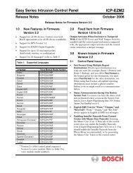
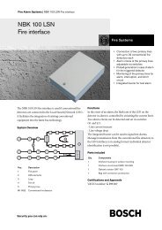
Network1 2NetworkNetwork1 21 2TrunkTrunkTrunkRS 232 Port 1RS 232FaultOK FaultPort 2RS 232 Port 1RS 232FaultOKFaultPort 2RS 232 Port 1RS 232FaultOKFaultPort 2Audio In 1 Audio Out 1 Audio In 2 Audio Out 2Audio In 1 Audio Out 1 Audio In 2 Audio Out 2Audio In 1 Audio Out 1 Audio In 2 Audio Out 2Mains115: 100-120V 50-60Hz T2.5A 250V230: 220-240V 50-60Hz T2A H 250VMains115: 100-120V 50-60Hz T2.5A 250V230: 220-240V 50-60Hz T2A H 250VMains115: 100-120V 50-60Hz T2.5A 250V230: 220-240V 50-60Hz T2A H 250V<strong>DCN</strong> <strong>Next</strong> <strong>Generation</strong> | Installation and User Instructions | System Design and Planning en | 161.6 Power capacity1.6.1 IntroductionIt is important that the devices in the <strong>DCN</strong> do not usemore total power than you supply to the devices. Eachdevice uses power and most devices do not have anindependent power supply.1.6.2 Power consumptionThe table 1.2 shows the power each device in the <strong>DCN</strong>uses.table 1.2: Power consumptionDeviceWatt<strong>DCN</strong>-CON 3.4<strong>DCN</strong>-CONCS 3.7<strong>DCN</strong>-CONFF 4.2<strong>DCN</strong>-CONCM 4.2<strong>DCN</strong>-DDB 2.0<strong>DCN</strong>-DDI 4.9<strong>DCN</strong>-DISL 2.75<strong>DCN</strong>-DISS 2.75<strong>DCN</strong>-DISCS 2.9<strong>DCN</strong>-DISD 2.8<strong>DCN</strong>-DISDCS 3.15<strong>DCN</strong>-DISV 3.05<strong>DCN</strong>-DISVCS 3.20<strong>DCN</strong>-EPS 0.1<strong>DCN</strong>-FCS 0.9<strong>DCN</strong>-FVU 1.0<strong>DCN</strong>-FVU-CN 1.0<strong>DCN</strong>-IDESK 3.6LBB4114/00 1.3LBB4115/00 1.41.6.3 Power supplies1.6.3.1 IntroductionThe devices that supply power to the <strong>DCN</strong> are thecentral control unit and the extension power supply(refer to figure 1.1 and figure 1.3). The power that thecentral control unit supplies includes the power that theoptical network uses.1.6.3.2 <strong>DCN</strong>-CCU<strong>DCN</strong>-CCU<strong>DCN</strong>-CCU<strong>DCN</strong>-CCU1 2 230P
CautionR isk of electric shock.Do not open.AvisR isk of electric shock.Do not open.CautionR isk of electric shock.Do not open.AvisR isk of electric shock.Do not open.TrunkTrunk1 21 2eRS 232RS 232Audio In 1 Audio Out 1 AudioIn2 Audio Out 2Audio In 1 Audio Out 1 AudioIn2 Audio Out 2Mains115: 100-120V 50-60Hz T2.5A 250V230: 220-240V 50-60Hz T2A H 250VMains115: 100-120V 50-60Hz T2.5A 250V230: 220-240V 50-60Hz T2A H 250V<strong>DCN</strong> <strong>Next</strong> <strong>Generation</strong> | Installation and User Instructions | System Design and Planning en | 171.6.3.3 <strong>DCN</strong>-CCUB<strong>DCN</strong>-CCUB2301.6.4 Overload indicationEach <strong>DCN</strong> socket of the central control unit andextension power supply has a red LED that comes on toshow that there is a power overload. An overload occurswhen:• The necessary power for the devices is greater thanthat supplied.• A short-circuit occurs.P
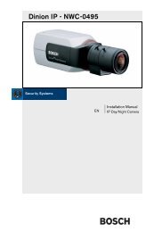
<strong>DCN</strong> <strong>Next</strong> <strong>Generation</strong> | Installation and User Instructions | System Design and Planning en | 181.7.3 Power correctionThe type and number of devices connected to a socketaffects the necessary power (refer to section 1.6.2 andsection 1.6.3). The length of the extension cablesconnected to the socket affects the available power.The cable correction graph (refer to figure 1.4) correctsthe power level to compensate for the length of theextension cable. For each <strong>DCN</strong> socket:1 Find the power consumption of each device from theconsumption table (refer to table 1.2). Add togetherthe power used by all the devices.2 Calculate the cable length from the socket to thefurthest device in the trunk.3 Find the value from step 1 on the vertical axis (Y) ofthe graph (refer to figure 1.4). Find the value fromstep 2 on the horizontal axis (X). The graphcalculates the power consumption values for thelength of the extension cable.8580757081768465707860657280Y: Power (Watt)55504540353025206054494338322721666054484236302473666053464033268275676052453730857768605142348373645546368070605040766554438472604880665375608568 7315161820222527303236404551551011121315171820212426303436566678910111213151718020 40 60 80 100 120 140 160 180200 220 240 250<strong>DCN</strong>-CCU, <strong>DCN</strong>-CCUB+ <strong>DCN</strong>-EPSX: Extension cable (m)figure 1.4: Power correction graph1.7.4 Open-ended <strong>DCN</strong> cables‘Open-ended’ <strong>DCN</strong> cables are <strong>DCN</strong> cables of which thesocket is not connected to a device in the <strong>DCN</strong>.‘Open-ended’ cables can cause an incorrect operation ofthe system. You can ‘close’ the extension cable with atermination plug (refer to chapter 43). When the‘open-ended’ cable is connected to a termination plug,the system operates correctly.<strong>Bosch</strong> Security Systems | 2005-09 | 9922 141 70524
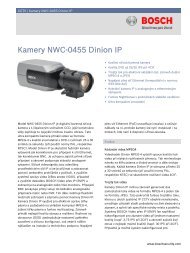
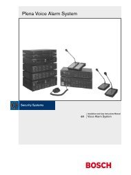
Network48V1 248VTrunk1 2RS 232 Port 1RS 232FaultNC C C NOPort 2Audio In 1 Audio Out 1 Audio In 2 Audio Out 2Mains115: 100-120V 50-60Hz T2.5A 250V230: 220-240V 50-60Hz T2A H 250V<strong>DCN</strong> <strong>Next</strong> <strong>Generation</strong> | Installation and User Instructions | System Design and Planning en | 191.8 Examples1.8.1 Cable lengthsLegendR Regenerative tap-off<strong>DCN</strong>-CCU230<strong>DCN</strong>-EPS2mTrunkTap-offInOutOutOutTrunkLBB4114/00100 mLBB4114/00100 mRRLBB4114/00100 mLBB4114/00100 mRR240 m240 mLBB4114/00LBB4114/002m2mLBB4114/00LBB4114/00250 m (max)250 m (max)<strong>DCN</strong>-DIS<strong>DCN</strong>-DIS<strong>DCN</strong>-DIS<strong>DCN</strong>-DIS444x2m=8m434x2m=8m<strong>DCN</strong>-DIS1figure 1.5: Example with cable lengthsPoint IThe maximum available power with 240 m of extensioncables is 19 W (refer to figure 1.4). Because the first andsecond trunk splitter use 2.6 W, the available power atpoint I is 19 W.Point IIThe maximum available power with 240 m of extensioncable is 25 W (refer to figure 1.4). Because the first andsecond trunk splitter use 2.6 W, the available power atpoint II is 22.4 W.<strong>Bosch</strong> Security Systems | 2005-09 | 9922 141 70524
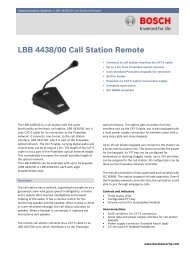
Network48V1 248VTrunk1 2RS 232 Port 1RS 232FaultNC C C NOPort 2Audio In 1 Audio Out 1 Audio In 2 Audio Out 2Mains115: 100-120V 50-60Hz T2.5A 250V230: 220-240V 50-60Hz T2A H 250V<strong>DCN</strong> <strong>Next</strong> <strong>Generation</strong> | Installation and User Instructions | System Design and Planning en | 211.8.3 Conference devices<strong>DCN</strong>-CCU230LBB4114/0010 m 10 m4520 m<strong>DCN</strong>-CON5410 m10 m4252figure 1.7: Example with conference units (<strong>DCN</strong>-CON)table 1.4: Example with conference units (<strong>DCN</strong>-CON)Socket Power for devices Cable length Corrected powerTrunk 1 51.5 W 40 m 61.8 WTrunk 2 57.0 W 20 m 62.2 W<strong>Bosch</strong> Security Systems | 2005-09 | 9922 141 70524
<strong>DCN</strong> <strong>Next</strong> <strong>Generation</strong> | Installation and User Instructions | System Design and Planning en | 221.8.4 <strong>DCN</strong>-CCU(B) power correctionAll examples use the power correction graph (refer tofigure 1.4).table 1.5: <strong>DCN</strong>-CCU(B) power correction examplesExample Y X Diagram Calculation<strong>DCN</strong>-DISS<strong>DCN</strong>-DISL65 0 1 2323 x 2.75 = 63.25 W23 x2m<strong>DCN</strong>-DISD 65 0 23 x 2.8 = 64.4 W1 2323x2m<strong>DCN</strong>-DISCS 65 0 22 x 2.9 = 63.8 W1 2222x2m<strong>DCN</strong>-DISDCS 65 0 20 x 3.15 = 63 W1 2020 x2m<strong>DCN</strong>-DISV 65 0 21 x 3.05 = 64.05 W1 2121x2m<strong>DCN</strong>-DISVCS 65 0 20 x 3.2 = 64 W1 2020 x2m<strong>DCN</strong>-DDI 65 0 13 x 4.9 = 63.7 W1 1313 x2m<strong>DCN</strong>-CON 65 0 19 x 3.4 = 64.6 W1 1919 x2m<strong>DCN</strong>-CONCS 65 0 17 x 3.7 = 62.96 W1 1717x2m<strong>DCN</strong>-CONFF 65 0 15 x 4.2 = 63 W1 1515 x2m<strong>Bosch</strong> Security Systems | 2005-09 | 9922 141 70524
<strong>DCN</strong> <strong>Next</strong> <strong>Generation</strong> | Installation and User Instructions | System Design and Planning en | 23table 1.6: <strong>DCN</strong>-CCU(B) power correction examples (continued)Device Y X Diagram Calculation<strong>DCN</strong>-FCS 65 0 150 LBB41145170 70 x 0.9 = 63 W1 x 1.3 = 1.3 W +64.3 W50 x2m2m20 x2m<strong>DCN</strong>-DISS 38 100 LBB4116 LBB41141 13 13 x 2.75 = 35.75 W1 x 1.3 = 1.3 W +37.1 W100 m2m13x2m<strong>DCN</strong>-DDI 38 100 LBB4116 LBB41141 17 7 x 4.9 = 34.3 W1 x 1.3 = 1.3 W +35.6 W100 m2m7x2m<strong>DCN</strong>-CON 38 100 LBB4116 LBB41141 10 10 x 3.4 = 34 W1 x 1.3 = 1.3 W +35.3 W100 m2m10 x2m<strong>DCN</strong>-FCS 38 100 LBB4116 LBB41141 40 40 x 0.9 = 36 W1 x 1.3 = 1.3 W +37.3 W100 m2m40 x2m<strong>Bosch</strong> Security Systems | 2005-09 | 9922 141 70524
<strong>DCN</strong> <strong>Next</strong> <strong>Generation</strong> | Installation and User Instructions | System Design and Planning en | 241.8.5 <strong>DCN</strong>-EPS power correctionThe examples use the power correction graph (refer tofigure 1.4).table 1.7: <strong>DCN</strong>-EPS power correction examplesExample Y X Diagram Calculation<strong>DCN</strong>-DISS<strong>DCN</strong>-DISL85 0 1 3030 x 2.75 = 82.25 W30 x2m<strong>DCN</strong>-DISD 85 0 30 x 2.8 = 84 W1 3030x2m<strong>DCN</strong>-DISCS 85 0 29 x 2.9 = 84.1 W1 2929 x2m<strong>DCN</strong>-DISDCS 85 0 26 x 3.15 = 81.9 W1 2626 x2m<strong>DCN</strong>-DISV 85 0 27 x 3.05 = 82.35 W1 2727x2m<strong>DCN</strong>-DISVCS 85 0 26 x 3.2 = 83.2 W1 2626 x2m<strong>DCN</strong>-DDI 85 0 17 x 4.9 = 83.3 W1 1717x2m<strong>DCN</strong>-CON 85 0 25 x 3.4 = 85 W1 2525 x2m<strong>DCN</strong>-CONCS 85 0 22 x 3.7 = 81.4 W1 2222x2m<strong>DCN</strong>-CONFF 85 0 20 x 4.2 = 84 W1 2020 x2m<strong>Bosch</strong> Security Systems | 2005-09 | 9922 141 70524
<strong>DCN</strong> <strong>Next</strong> <strong>Generation</strong> | Installation and User Instructions | System Design and Planning en | 25table 1.8: <strong>DCN</strong>-EPS power correction examples (continued)Device Y X Diagram Calculation<strong>DCN</strong>-FCS 85 0 150 LBB41145193 93 x 0.9 = 83.7 W1 x 1.3 = 1.3 W +85 W50 x2m2m43 x2m<strong>DCN</strong>-DISS 50 100 LBB4116 LBB41141 17 17 x 2.75 = 46.75 W1 x 1.3 = 1.3 W +48.1 W100 m2m17x2m<strong>DCN</strong>-DDI 50 100 LBB4116 LBB41141 19 9 x 4.9 = 44.1 W1 x 1.3 = 1.3 W +45.4 W100 m2m9 x2m<strong>DCN</strong>-CON 50 100 LBB4116 LBB41141 14 14 x 3.4 = 34 W1 x 1.3 = 1.3 W +48.9 W100 m2m14x2m<strong>Bosch</strong> Security Systems | 2005-09 | 9922 141 70524
<strong>DCN</strong> <strong>Next</strong> <strong>Generation</strong> | Installation and User Instructions | System Design and Planning en | 272 Optical network design2.1 IntroductionThe <strong>DCN</strong> <strong>Next</strong> <strong>Generation</strong> has two parts: the <strong>DCN</strong> andthe optical network. This chapter tells how to design theoptical network.2.2 Calculation toolThe calculation tool makes the planning and design ofthe optical network easier. You can find the calculationtool on the CD-ROM that is supplied with your system.2.3 LimitsMake sure that these limits are not exceeded when youmake the optical network:Limit 1: Control capacityThe maximum number of nodes in the optical networkis 63 (refer to section 2.4).Limit 2: Number of devicesThe maximum number of devices that you can connectto the optical network of the central control unit is 16.Limit 3: Power capacityThe maximum power that the optical network socketsof the central control unit can supply is 65 W (refer tosection 2.5).Limit 4: CablesRefer to section 2.6:• The maximum length of a POF cable is 50 m.• The maximum cable length (POF and GOF) of theoptical network is dependent on the number ofnodes in the optical network.• The minimum bend radius of a 90 degree bend in aPOF cable is 25 mm.• The minimum coiling radius of a POF cable is100 mm.2.4 Control capacityEach device in the optical network has a number ofnodes (refer to table 2.1). The maximum number ofnodes in the optical network is 63.table 2.1: NodesDeviceNodes<strong>DCN</strong>-CCU 2LBB4402/00 1LBB4404/00 1LBB4410/00 1LBB4414/10 0INT-TX04 1INT-TX08 2INT-TX16 4INT-TX32 8PRS-4DEX4 12.5 Power capacity2.5.1 IntroductionIt is important that the devices in the optical network donot use more total power than you supply to thedevices. Each device uses power and most devices donot have an independent power supply.2.5.2 Power consumptionThe table 2.2 shows the power each device in theoptical network uses.table 2.2: Power consumptionDeviceWattLBB4402/00 7.6LBB4404/00 10.5LBB4410/00 3.9LBB4414/10 4.6PRS-4DEX4 6.0NoteThe Integrus transmitters do not use power fromthe system.<strong>Bosch</strong> Security Systems | 2005-09 | 9922 141 70524
NetworkNetworkNetwork1 21 21 2TrunkTrunkTrunkRS 232 Port 1RS 232FaultOKFaultPort 2RS 232 Port 1RS 232FaultOKFaultPort 2RS 232 Port 1RS 232FaultOKFaultPort 2Audio In 1 Audio Out 1 Audio In 2 Audio Out 2Audio In 1 Audio Out 1 Audio In 2 Audio Out 2Audio In 1 Audio Out 1 Audio In 2 Audio Out 2Mains115: 100-120V 50-60Hz T2.5A 250V230: 220-240V 50-60Hz T2A H 250VMains115: 100-120V 50-60Hz T2.5A 250V230: 220-240V 50-60Hz T2A H 250VMains115: 100-120V 50-60Hz T2.5A 250V230: 220-240V 50-60Hz T2A H 250V<strong>DCN</strong> <strong>Next</strong> <strong>Generation</strong> | Installation and User Instructions | System Design and Planning en | 282.5.3 Power supplyThe device that supplies power to the optical network isthe central control unit, refer to figure 2.1. The powerthat the central control unit supplies includes the powerthat the <strong>DCN</strong> uses.<strong>DCN</strong>-CCU2.5.4 Overload indicationEach optical network socket of the central control unithas a red LED that comes on to show that there is apower overload. An overload occurs when thenecessary power for the devices is greater than thatsupplied. The sockets are set to off and the devicesconnected to the central control unit do not operate.The socket checks every 8 seconds.1 2 230<strong>DCN</strong>-CCUP
<strong>DCN</strong> <strong>Next</strong> <strong>Generation</strong> | Installation and User Instructions | System Design and Planning en | 292.6.3 Cable couplersYou can use the LBB4419/00 Cable Couplers toconnect optical network cables to each other. A cablecoupler causes optical attenuation. Each cable couplerdecreases the maximum distance between two devicesin the optical network (normally 50 meters) with20 meters.2.6.4 Maximum cable lengthThe maximum cable length (LBB4416 and GOF) of theoptical network is dependent on:• The number of nodes• The number of LBB4414/10 Fiber InterfacesDo as follows:1 Find the number of nodes of each device from thenode value table (refer to table 2.1). Add together thenodes of all devices.2 With the value of step 1, use the graph (refer tofigure 2.2) to find the maximum cable length withoutLBB4414/10 Fiber Interfaces.3 Count the number of LBB4414/10 Fiber Interfaces.Each fiber interface decreases the maximum cablelength from step 2 with 18 m.Max. cable length (m)2150205019501850175016501550145013501250115010509500 5 10 15 20 2530 35 40 45 50 55 60 63Nodesfigure 2.2: Cable correction graph<strong>Bosch</strong> Security Systems | 2005-09 | 9922 141 70524
<strong>DCN</strong> <strong>Next</strong> <strong>Generation</strong> | Installation and User Instructions | System Design and Planning en | 302.6.5 BendingThe minimum bend radius of a 90 degree bend in anLBB4416 cable is 110 mm (refer to figure 2.3). A180 degree bend is the same as two 90 degree bends.R=110 mm2.7 Example layouts2.7.1 IntroductionThe number and type of devices that make the opticalnetwork give the layout of the optical network. Thischapter shows examples of the possible layouts ofoptical networks.2.7.2 Basic optical networkRefer to figure 2.5 for an example of a basic opticalnetwork.<strong>DCN</strong>-CCUfigure 2.3: Bend radius2.6.6 CoilingThe minimum coiling radius of an LBB4416 cable is110 mm (refer to figure 2.4).LBB4404/00LBB4402/00R=110 mmPRS-4DEX4INT-TXfigure 2.5: Basic optical networkfigure 2.4: Coiling radius<strong>Bosch</strong> Security Systems | 2005-09 | 9922 141 70524
<strong>DCN</strong> <strong>Next</strong> <strong>Generation</strong> | Installation and User Instructions | System Design and Planning en | 312.7.3 Redundant cablesThe basic optical network (refer to figure 2.5) has noredundant cables. If the cable between the centralcontrol unit (<strong>DCN</strong>-CCU) and the audio expander(LBB4402/00) breaks, the central control unit cannottransmit data to the audio expander. A solution for thisproblem is to use redundant cable (refer to figure 2.6).2.7.4 Tap-offsThe network splitter (LBB4410/00) lets you maketap-offs (refer to figure 2.7). Tap-offs cannot beredundant. If the cable between the network splitter andthe digital audio expander (PRS-4DEX4), becomesdefective, the digital audio expander has no connectionto the central control unit.<strong>DCN</strong>-CCU<strong>DCN</strong>-CCULBB4404/00LBB4402/00LBB4402/00LBB4410/00PRS-4DEX4INT-TXPRS-4DEX4INT-TXfigure 2.6: Redundant optical networkfigure 2.7: Redundant optical network with tap-offThe basic system with no redundant cables has noconnection between the cobranet interface(LBB4404/00) and the central control unit (<strong>DCN</strong>-CCU).A system with redundant cables has a connectionbetween the Cobranet Interface and the central controlunit. This connection makes a ring. If a cable breaks, theoptical network continues to operate.The maximum total power of all devices in theredundant optical network is 65 W. If the opticalnetwork is defective near the central control unit, theother socket can supply power to all of the opticalnetwork.<strong>Bosch</strong> Security Systems | 2005-09 | 9922 141 70524
<strong>DCN</strong> <strong>Next</strong> <strong>Generation</strong> | Installation and User Instructions | System Design and Planning en | 323 Wireless languagedistributionYou can connect the system to an Integrus digitalinfra-red language distribution system. This system has atransmitter, radiators and receivers.NoteRefer to the Integrus Installation and UserInstructions for more data.figure 3.1: Integrus<strong>Bosch</strong> Security Systems | 2005-09 | 9922 141 70524
<strong>DCN</strong> <strong>Next</strong> <strong>Generation</strong> | Installation and User Instructions | System Design and Planning en | 334 CobraNetCobraNet is a standard for the transport of real-timedigital audio and control data through an Ethernetnetwork. A CobraNet network can transport amaximum of 64 channels of 48 kHz, 20-bit audiothrough a 100 Mbit link connection in each direction.Many manufacturers of professional audio devicessupport the CobraNet standard.The <strong>DCN</strong> <strong>Next</strong> <strong>Generation</strong> digital congress networkcan connect to CobraNet networks with theLBB4404/00 Cobranet Interface. For example, you canuse the LBB4404/00 Cobranet Interface to:• Benefit from Ethernet infrastructure• Transport audio signals over large distancesPC data, for example data from the <strong>DCN</strong> <strong>Next</strong><strong>Generation</strong> Open Interface can co-exist with CobraNetdata on the same Ethernet network when you usemanaged Ethernet switches that are approved by PeakAudio.NoteRefer to the website of Peak Audio(www.peakaudio.com) for:• More data about CobraNet networks.• A list of approved Ethernet switches.<strong>Bosch</strong> Security Systems | 2005-09 | 9922 141 70524
<strong>DCN</strong> <strong>Next</strong> <strong>Generation</strong> | Installation and User Instructions | System Design and Planning en | 345 User set-up5.1 Public areas5.1.1 Hall displaysPut the hall displays in a position where users can easilysee the display. Do not put the display in direct lightingor sunlight. The following has an effect on the visibilityfor the specified system:• The distance that is necessary to see the display.• The character size of the displays.• Contrast and intensity of the lighting conditions.The supplier of the hall display recommends allnecessary adjustments.5.3 Speaking distanceWe recommend the distance that people speak to themicrophones is between 0.2 m and 0.4 m.5.4 Interpreter boothsMake sure each interpreter booth has sufficientdimensions to let interpreters use the interpreter booth.The International Organization for Standardization(ISO) gives the specification for interpreter booths.Refer to standard ISO 2603 ‘Booths for simultaneousinterpretation - General characteristics and equipment’for more data. Most international conferences put stresson the interpreters thus interpreters do their work inturns.5.1.2 WalkwaysKeep public areas clear of system and extension cablesand connections.5.2 Headphones/headsetsPut headphones and headsets with:• Interpreter desks.• Concentus delegate and chairman units.• Channel selectors.• Discussion units.• Integrus receivers.Acoustic feedback between the connected headphonesor headsets and the microphone occurs when:• The volume level is set too high.• The headphones are too close to enabledmicrophones.You must tell the users to keep sufficient distance fromthe microphones or not to set the volume level higherthan is necessary.NoteAll <strong>DCN</strong> devices have a level reduction function.<strong>Bosch</strong> Security Systems | 2005-09 | 9922 141 70524
<strong>DCN</strong> <strong>Next</strong> <strong>Generation</strong> | Installation and User Instructions | System Design and Planning en | 356 Device set-up6.1 GeneralCautionDo not put objects on top of devices. Objectscan fall through the airflow holes. A blockage ofthe airflow holes can prevent airflow and causea risk of fire.CautionDo not put the devices near or above a radiator,heat grill or in direct sunlight.CautionDo not cause vibration of the devices.• Make sure that the area is clean.• Make sure that the air is sufficiently cool.• Make sure that there is sufficient lighting.6.2 CablesUse different cable ducts for the extension and mainscables. Identify each cable with a label and dividetrunks to manageable geographic locations. In publicareas where people can touch or move above theconnectors and cables, use metal protection covers.Refer to the applicable protection specification of theprotection covers.6.3 TemperatureWhen devices are in a 19-inch rack, make sure there israck space between the devices to let sufficient airflow.Forced airflow may be necessary to keep thetemperature of the devices below the maximumtemperature (refer to section 7.2). This extends thelifetime of the devices.6.4 VentilationKeep a good airflow. Airflow holes are in the front, rightand left sides of the central control units, audioexpanders and extension power supplies.• Put the devices on a hard and level surface.• Put the central control unit at minimum distance of0.10 m from walls to make sure of sufficient airflow.6.5 CleaningCautionDo not use alcohol, ammonia or petroleumsolvents or abrasive cleaners to clean thedevices.1 Disconnect the mains power supply from thedevices, if you want to clean the devices.2 Use a soft cloth that is not fully moist with a weaksoap and water solution.3 Let the device fully dry before you operate thedevice again.6.6 StorageNoteIf the central control unit is stopped ordisconnected from the mains power supply formore than 100 days, the values of all systemparameter are erased. This includes all thevalues of the parameters of the interpreterdesks.1 Disconnect the mains power supply from thedevices, if you do not use the devices for a long time.2 Keep the devices in a clean and dry area with asufficient airflow.<strong>Bosch</strong> Security Systems | 2005-09 | 9922 141 70524
<strong>DCN</strong> <strong>Next</strong> <strong>Generation</strong> | Installation and User Instructions | System Design and Planning en | 366.7 Acoustic feedbackAcoustic feedback (‘howling’) occurs when the sound ofthe loudspeakers or headphones in the system is sent tothe system again by enabled microphones.table 6.1: Acoustic feedbackSource Quick solution Structural solutionThe acoustic feedback is caused bythe loudspeakers of the contributiondevices.The acoustic feedback is caused byan external public address systemthat is connected to the <strong>DCN</strong> <strong>Next</strong><strong>Generation</strong> digital congressnetwork.The acoustic feedback is caused bythe headphones that are connectedto the contribution devices.Decrease the volume level of thesystem. For example, with the knobon the front of the central controlunit (refer to section 8.6.3).Decrease the volume level of thepublic address system or the <strong>DCN</strong><strong>Next</strong> <strong>Generation</strong> digital congressnetwork.Tell the chairmen and the delegatesto decrease the volume level of theirheadphones with their contributiondevices.Do as follows:1 Install a feedback suppressorbetween audio input 2 and audiooutput 2 of the central controlunit.2 Set the audio routing mode ofthe system to Insertion (refer tosection 10.4).Install a feedback suppressorbetween audio output 1 and theinput of the external public addresssystem.Install and configure theheadphones level reduction of thecontribution devices. (Refer to thesection about the contributiondevices.)<strong>Bosch</strong> Security Systems | 2005-09 | 9922 141 70524
<strong>DCN</strong> <strong>Next</strong> <strong>Generation</strong> | Installation and User Instructions | System Design and Planning en | 377 Technical data7.1 System electrical and electro-acoustic characteristics7.1.1 Generaltable 7.1: Electro-acoustic characteristicsNominal input level:85 dB SPLOverload input level:110 dB SPLAutomatic gain reduction (not for PA-floor output):• 24 dB (interpretation channels)• 12 dB (delegate loudspeaker channel)Automatic gain reduction with:• 3 dB (2 microphones on• 6 dB (4 or more microphones on)Loudspeaker gain control:24 x 1 dB and off (mute)7.1.2 Transmission links• From delegate microphone to interpreter headphones• From delegate microphone to delegate headphones• From interpreter microphone to delegate headphones• From interpreter microphone to interpreter headphones• From auxiliary input to delegate headphones• From auxiliary input to interpreter headphones• From delegate microphone to auxiliary output• From interpreter microphone to auxiliary outputtable 7.2: Transmission linksFrequency response:• 125 Hz to 20 kHz (General)• 125 Hz to 3.5 kHz (Intercom links)Harmonic distortion:< 0.5%Harmonic distortion @ overload:< 1%Crosstalk attenuation @ 4 kHz:> 80 dBDynamic range:> 90 dB<strong>Bosch</strong> Security Systems | 2005-09 | 9922 141 70524
<strong>DCN</strong> <strong>Next</strong> <strong>Generation</strong> | Installation and User Instructions | System Design and Planning en | 387.1.3 Combined devices from input to output• Delegate microphone with transmission link to interpreter headphones• Delegate microphone with transmission link to delegate headphones• Delegate microphone with transmission link to auxiliary output• Interpreter microphone with transmission link to interpreter headphones• Interpreter microphone with transmission link to delegate headphones• Interpreter microphone with transmission link to auxiliary outputtable 7.3: Combined devices from input to outputTypical frequency response:125 Hz to 20 kHzFront-to-random sensitivity index:> 4.6 dBRated equivalent sound pressure level due to inherent noise:< 25 dB(A)Total harmonic distortion @ overload:< 1%Crosstalk attenuation:> 80 dB7.2 Environmental conditionstable 7.4: Environmental conditionsWorking conditions:Fixed, stationary, transportableTemperature range:• -20 to +70 °C (transport)• +5 to +45 °C (operation)• For EPS and contribution devices with an LCD, the maximum temperature is +40 °C.Relative humidity:< 95%7.3 SafetyAccording to EN 60065, and according to CAN/CSA-E65-94 (C and US) and UL 6500-96 for all non-stationaryequipment, <strong>DCN</strong>-CCU and <strong>DCN</strong>-EPS.7.4 Electro-magnetic compatibilitytable 7.5: Electromagnetic compatibilityEMC emission:According to harmonized standard EN 55013 and FCC rules (part 15) complying with the limits for a class A digitaldevice.EMC immunity:According to harmonized standard EN 55020.EMC approvals:Affixed with the CE mark. EC directive 89/336 EEC.<strong>Bosch</strong> Security Systems | 2005-09 | 9922 141 70524
<strong>DCN</strong> <strong>Next</strong> <strong>Generation</strong> | Installation and User Instructions | System Design and Planning en | 397.5 Miscellaneoustable 7.6: MiscellaneousESD:According to IEC 801-2; contact 4 kV, air 8 kV. Fast transients to the mains and data lines according to IEC 801-4.Mains harmonics:Prepared to EN 60555-2 Class AShock resistance:According to IEC 68.2.29 EbVibration resistance:According to IEC 68.2.6 Fc, procedure AAdditional immunity tests:According to IEC 801-3. Field strength 3 V/m in the frequency range 80 - 1000 MHz. Severity level 3: not affectingnormal operation.Other legal requirements:No cadmium used other than in the Nickel-Cadmium battery housed in the central unit.<strong>Bosch</strong> Security Systems | 2005-09 | 9922 141 70524
<strong>DCN</strong> <strong>Next</strong> <strong>Generation</strong> | Installation and User Instructions | System Design and Planning en | 40Intentionally left blank.<strong>Bosch</strong> Security Systems | 2005-09 | 9922 141 70524
<strong>DCN</strong> <strong>Next</strong> <strong>Generation</strong> | Installation and User Instructions | Central Control Devices en | 41Section 2 - Central Control Devices<strong>Bosch</strong> Security Systems | 2005-09 | 9922 141 70524
<strong>DCN</strong> <strong>Next</strong> <strong>Generation</strong> | Installation and User Instructions | Central Control Devices en | 428 <strong>DCN</strong>-CCU Central ControlUnit8.1 IntroductionThe <strong>DCN</strong>-CCU Central Control Unit controls thesystem. The central control unit can operate with orwithout a control PC.NoteThe <strong>DCN</strong>-CCU-UL is the CSA/UL approvedversion of the <strong>DCN</strong>-CCU.8.2 Controls, connectors andindicators8.2.1 Front viewThe front of the central control unit (refer to figure 8.1)contains:1 On/off switch - Starts and stops the central controlunit.2 Display - Shows the configuration menu (refer tosection 8.6).3 Knob - Operates the configuration menu (refer tosection 8.6). You can also change the volume level ofthe system with the knob.4 Headphones socket - Connects headphones tothe central control unit (refer to section 8.5.4).152 3 46 7CautionRisk of electric shock.Do not open.AvisRisk of electric shock.Do not open.RS 232 Port 1MainsRS 232Port 2Audio In 1 Audio Out 1 AudioIn2 Audio Out 2Network1 2Trunk1 2Fault230OKFail115: 100-120V 50-60Hz T2.5A 250V230: 220-240V 50-60Hz T2AH250V8 910 11 12 11 12 13 14figure 8.1: Front and rear views<strong>Bosch</strong> Security Systems | 2005-09 | 9922 141 70524
<strong>DCN</strong> <strong>Next</strong> <strong>Generation</strong> | Installation and User Instructions | Central Control Devices en | 438.2.2 Rear viewThe rear of the central control unit (refer to figure 8.1)contains:5 RS232 ports - Connects a PC, remote controllers orvideo cameras to the central control unit (refer tosection 8.5.8).6 Power inlet - Connects the central control unit tothe mains power supply with a power cable (refer tosection 8.5.1).7 Ground screw - Connects the central control unitto ground.8 Optical network sockets - Connects the centralcontrol unit to the optical network (refer to section8.5.3).9 <strong>DCN</strong> sockets - Connect the central control unit tothe <strong>DCN</strong> (refer to section 8.5.2).10 Fault contact - Connect the central control unit todevices to sense the condition of the central controlunit (refer to section 8.5.7).11 Audio inputs - Connect the central control unit toexternal analog audio sources (refer to section 8.5.5).12 Audio outputs - Connect the central control unitto external analog audio devices (refer to section8.5.6).13 Voltage selector - Selects the voltage on which thecentral control unit must operate (refer to section8.5.1).14 Fuse holder - Prevents damage to the internalpower supply unit of the central control unit (refer tosection 8.5.1).8.3 Internal settings8.3.1 OverviewCautionBefore you open the central control unit,disconnect it from the mains power supply.Electrical discharges from the mains powersupply can kill you.CautionBefore you open the central control unit, takemeasures to prevent electro-static discharges.The PCBs of the central control unit (refer to figure 8.2)contain:15 Software LEDs - Show the condition of thesoftware of the central control unit. When thesoftware runs correctly, the yellow and green LEDflash.16 S600 switches - Reserved (refer to section 8.3.2).17 X605 jumper block - Enables or disables thewatchdog (refer to section 8.3.5).18 Reset switch - Starts the central control unit again.19 Optical network processor indicator - Comeson when the optical network processor operatescorrectly.20 S500 switches - Configure the RS232 ports of thecentral control unit (refer to section 8.3.3).21 X600 jumper block - Connects and disconnectsthe internal back-up battery of the central controlunit (refer to section 8.3.4).22 X104 jumper block - Connects and disconnectsthe mechanical ground and the electrical ground(refer to section 8.3.6).23 Fuse - Prevents damage to the electroniccomponents in the central control unit.<strong>Bosch</strong> Security Systems | 2005-09 | 9922 141 70524
T1T2R2T3 R3T4T5T6R1R4R5R6P1P2P3P4N1N2T7 R7 P7 N7 M7 L7 K7T8 R8 P8 N8 M8 L8 K8T9 R9 P9 N9 M9 L9 K9M1M2L1L2L3L4K1K2K3K4K5K6K10K11K12K13K14K15K16J1 H1 G1 F1J2 H2 G2 F2J3 H3 G3 F3J4 H4 G4 F4J5J6J8G5G8J9 H9 G9J10J11J12J13J14H5H6H7H8H10H11H12H13H14G6G7G10G11G12G13G14F5F6F7F8F9F10F11F12F13F14F15F16E1E2E3E4E5E6E7E8E9E10E11E12E13E14E15E16D1D2D3D4D5D6D7D8D9D10D11D12C1C2C3C4B1B2B3A1A2A3B4 A4C5 B5 A5C6 B6 A6C7 B7 A7C8 B8 A8C9C10C11C12B9B10B11B12A9A10A11A12D13 C13 B13 A13D14 C14 B14 A14D15 C15 B15 A15D16C16B16A16ONON1 2 3 4 5 6 7 81 2 3 4 5 6 7 8<strong>DCN</strong> <strong>Next</strong> <strong>Generation</strong> | Installation and User Instructions | Central Control Devices en | 44N3 M3N4 M4T10T11T12T13T14T15T16R10R12P5P6P10N5 M5L5N6 M6 L6N12P14 N14M10R11 P11 N11 M11R13R14R16P12P13P16N10N13N16M12M13M14L10L11L12L13L14R15 P15 N15 M15 L15L1623 22 2120 19X104S500X155S1000S800J15 H15 G15J16 H16 G16F100X1000B1000X1001G600X103B601B602B604X600X14X605S601S60015 16 1718figure 8.2: Internal settings<strong>Bosch</strong> Security Systems | 2005-09 | 9922 141 70524
<strong>DCN</strong> <strong>Next</strong> <strong>Generation</strong> | Installation and User Instructions | Central Control Devices en | 458.3.2 S600 switchestable 8.1: S600 switches (* = default)Switch Position DescriptionS600-1 ON*Reserved. Do not change the position of this switch.OFFS600-2 ONReserved. Do not change the position of this switch.OFF*S600-3 ONReserved. Do not change the position of this switch.OFF*S600-4 ONReserved. Do not change the position of this switch.OFF*S600-5 ONReserved. Do not change the position of this switch.OFF*S600-6 ONReserved. Do not change the position of this switch.OFF*S600-7 ONOFF*Reserved. Do not change the position of this switch.S600-8 ONOFF*Enables the download of new firmware.Normal operation.8.3.3 RS232 configurationUse the S500 switches to configure the RS232 ports ofthe central control unit (refer to table 8.2 and table 8.3).table 8.2: RS232 protocol (* = default)Protocol Port 1 Port 2S500-1 S500-2 S500-5 S500-6Open interface Off Off Off OffTerminal Off On Off OnFull On* Off* On OffCamera control On On On* On*table 8.3: RS232 baudrate (* = default)Baudrate Port 1 Port 2S500-3 S500-4 S500-7 S500-89.6k Off Off Off Off19.2k Off On Off* On*57.6k On Off On Off115.2k On* On* On On<strong>Bosch</strong> Security Systems | 2005-09 | 9922 141 70524
<strong>DCN</strong> <strong>Next</strong> <strong>Generation</strong> | Installation and User Instructions | Central Control Devices en | 468.3.4 Internal back-up batteryUse the X600 jumper block to connect and disconnectthe internal back-up battery of the central control unit(refer to table 8.4).NoteWhen your central control unit is new, you mustenergize the central control unit to charge theinternal back-up battery. The internal back-upbattery is fully charged after 24 hours.table 8.4: X600 jumper block (* = default)Jumper shunt Description1 and 2 * Connects the internal back-upbattery. When you stop thecentral control unit, the memoryof the central control unit is noterased.2 and 3 Disconnects the internalback-up battery. When you stopthe central control unit, thememory of the central controlunit is immediately erased. Thememory of the central controlunit contains:• The license code• The settings of theinterpreter desks.NoteYou only have a license code when you use thesystem in combination with:• The PC Control Software• A remote controller8.3.5 WatchdogUse the X605 jumper to enable or disable the watchdogof the central control unit (refer to table 8.5).table 8.5: X605 jumper block (* = default)Jumper shunt DescriptionPresentThe watchdog is disabled. Thecentral control unit does notstart again after an error.Not present* Enables the watchdog. Thecentral control unit starts againafter an error.NoteWhen you disable the watchdog, the systemcan operate incorrectly.8.3.6 GroundUse the X104 jumper block to connect and disconnectthe system ground and the ground of the central controlunit (refer to table 8.6). For example, you can connectthe system ground and the ground of the central controlunit to prevent hum.table 8.6: X104 jumper block (* = default)Jumper shunt Description1 and 2 Connects the system groundand the ground of the centralcontrol unit.2 and 3 * Disconnects the system groundand the ground of the centralcontrol unit.NoteWhen you connect the system ground to theground of more than one device in the system,you can create ground loops. Ground loops cancause hum.<strong>Bosch</strong> Security Systems | 2005-09 | 9922 141 70524
<strong>DCN</strong> <strong>Next</strong> <strong>Generation</strong> | Installation and User Instructions | Central Control Devices en | 478.4 InstallationInstall the central control unit in a 19-inch rack systemor on a flat surface. Four feet and two brackets aresupplied with the central control unit (refer to figure8.3).8.5 External connections8.5.1 Power supplyTo connect the central control unit to a mains powersupply do as follows:NoteThe <strong>DCN</strong>-CCU is configured for a voltage of220 - 240 V(AC). The <strong>DCN</strong>-CCU-UL isconfigured for a voltage of 100 - 120 V(AC).1 Set the voltage selector on the rear of the centralcontrol unit to the correct position (refer to table8.8).figure 8.3: Installationtable 8.7: Physical characteristicsDimensions (h x w x d), flat surface:92 x 440 x 400 mm (without brackets, with feet)Dimensions (h x w x d), 19-inch rack system:88 x 483 x 400 mm (with brackets, without feet)Weight:6.7 kg (without brackets, without feet)NoteWhen you install the central control unit in a19-inch rack system, the central control unitextends 36 mm in front of the brackets.table 8.8: Voltage selectorPower supply voltage Voltage selector90 to 132 V(AC) 115198 to 264 V(AC) 2302 Make sure that the fuse holder in the rear of thecentral control unit contains the correct fuse (refer totable 8.9).table 8.9: FusesVoltage selector Fuse115 T2.5A 250 V (UL 248)230 T2AH 250 V (IEC 60127)3 Connect a locally approved power cable to thecentral control unit (refer to figure 8.4).figure 8.4: Power supply<strong>Bosch</strong> Security Systems | 2005-09 | 9922 141 70524
<strong>DCN</strong> <strong>Next</strong> <strong>Generation</strong> | Installation and User Instructions | Central Control Devices en | 484 Connect the power cable to a power supply.CautionMake sure that the mains power supply isgrounded. Electrical discharges from the mainspower supply can kill you.8.5.3 Optical networkConnect the trunk of the optical network to the opticalnetwork sockets of the central control unit with opticalnetwork cables (refer to figure 8.6).8.5.2 <strong>DCN</strong>Connect the trunk of the <strong>DCN</strong> to the <strong>DCN</strong> sockets ofthe central control unit (refer to figure 8.5).LEDfigure 8.6: Optical networkLEDfigure 8.5: <strong>DCN</strong>Each <strong>DCN</strong> socket has a red LED that comes on if thereis an overload (refer to figure 8.5 and section 2.5.4).table 8.10: <strong>DCN</strong> connectionNumber of connections:2x <strong>DCN</strong> socketLocation:Rear sidePower supply:max. 65 W (refer to figure 1.1)Each optical network socket has a red LED that comeson if there is an overload (refer to figure 8.6 and section2.5.4).table 8.11: Optical network connectionsNumber of connections:2x proprietary socketsLocation:Rear sideNodes:2Power supply:max. 65 W (refer to figure 2.1)<strong>Bosch</strong> Security Systems | 2005-09 | 9922 141 70524
<strong>DCN</strong> <strong>Next</strong> <strong>Generation</strong> | Installation and User Instructions | Central Control Devices en | 498.5.4 HeadphonesYou can connect headphones to the headphones socketof the central control unit. The headphones must have a3.5 mm plug (refer to figure 8.7).2 3 18.5.5 Audio inputsYou can connect an external analog audio source to theaudio inputs of the central control unit. The centralcontrol unit has two audio inputs. Each audio input has(refer to figure 8.8):• 1 XLR socket for balanced signals. The electriccircuits behind the XLR sockets containtransformers.• 1 double cinch socket for unbalanced signals.figure 8.7: 3.5 mm headphones plug, connectiontable 8.12: 3.5 mm headphones plug, connectionNumberSignal1 Left2 Common3 RightNoteThe audio inputs change stereo signals in monosignals.2Audio In1NoteYou can also connect mono headphones to theheadphones socket.3 45You can select the signal that is available on theheadphones socket with the configuration menu (referto section 8.6.5).figure 8.8: Audio input, connectiontable 8.13: Audio input, connectionPin Type Signal Description1 XLR Xternal Shield/ground2 Live Positive3 Return Negative4 Cinch Live Signal in5 Return Shield/ground<strong>Bosch</strong> Security Systems | 2005-09 | 9922 141 70524
<strong>DCN</strong> <strong>Next</strong> <strong>Generation</strong> | Installation and User Instructions | Central Control Devices en | 50You can select the procedure that is used to send audiosignals through the central control unit with the audiorouting modes (refer to section 8.6.7).NoteYou can only connect line level sources to theaudio inputs of the central control unit. It is notpossible to connect microphone sources.table 8.14: Audio input details, line level signalsNumber of connections:• 1x XLR socket for each audio input• 1x double cinch socket for each audio inputLocation:Rear sideCable:Shielded cableMaximum level:Refer to appendix ANominal level:Refer to appendix AFrequency response:-3 dB @ 30 Hz and 20 kHzImpedance:• XLR: 22 kΩ• Cinch: 12 kΩSignal-to-noise ratio:> 85 dBA @ max. levelCMRR:> 60 dB @ 100 Hz> 50 dB @ 1 kHzCrosstalk attenuation:> 85 dB @ max. levelDistortion:< 0.1% @ 100 Hz @ -3 dB of the max. input8.5.6 Audio outputsYou can connect an audio recording device or a publicaddress system to the audio outputs of the centralcontrol unit. The central control unit has two audiooutputs. Each audio output has (refer to figure 8.9):• 1 XLR plug for balanced signals. The electric circuitsbehind the XLR plugs contain transformers.• 1 double cinch socket for unbalanced signals.NoteThe two cinch sockets contain the same monosignal.1Audio Outfigure 8.9: Audio output, connection23 4table 8.15: Audio output, connectionPin Type Signal Description1 XLR Xternal Shield/ground2 Live Positive3 Return Negative4 Cinch Live Signal out5 Return Shield/Ground5<strong>Bosch</strong> Security Systems | 2005-09 | 9922 141 70524
<strong>DCN</strong> <strong>Next</strong> <strong>Generation</strong> | Installation and User Instructions | Central Control Devices en | 51You can select the procedure that is used to send audiosignals through the central control unit with theavailable audio routing modes (refer to section 8.6.7).table 8.16: Audio output detailsNumber of connections:• 1x XLR plug for each audio output• 1x double cinch socket for each audio outputLocation:Rear sideCable:Shielded cableMaximum level:Refer to appendix ANominal level (audio output 1):Refer to appendix ANominal level (audio output 2):Refer to appendix AFrequency response:-3 dB @ 30 Hz and 20 kHzImpedance:< 100 ΩSignal-to-noise ratio:> 89 dBA @ max. levelCrosstalk attenuation:> 85 dB @ max. levelDistortion:< 0.1% @ 100 Hz @ - 3 dB of the max. input8.5.7 Fault contactUse the fault contact to send the condition of the centralcontrol unit to external devices. If the central controlunit operates correctly, the OK pins are internallyconnected. The central control unit internally connectsthe Fail pins when:• The central control unit is stopped.• The internal power supply unit operates incorrectly.• The central control unit does a reset.figure 8.10: Fault contactOKFailtable 8.17: Fault contactNumber of connections:4-pole plugLocation:Rear sideSignal:Potential-free change-over relayVoltage:Max. 24 V(DC), 15 V(AC)Current:Max. 500 mA<strong>Bosch</strong> Security Systems | 2005-09 | 9922 141 70524
<strong>DCN</strong> <strong>Next</strong> <strong>Generation</strong> | Installation and User Instructions | Central Control Devices en | 528.5.8 RS232 portsYou can connect a PC, remote controllers or videocameras to the RS232 ports of the central control unit(refer to chapter 11). The central control unit has 2RS232 ports (refer to figure 8.11). You can set theprotocol and the baudrate of the RS232 ports with theS500 switches (refer to section 8.3.3).519 6figure 8.11: RS232 port, connectiontable 8.18: RS232 port, connectionPin Definition Description1 DCD Data Carrier Select2 RxD Receive Data3 TxD Transmit Data4 DTR Data Terminal Ready5 SG Signal Ground6 DSR Data Set Ready7 RTS Request To Send8 CTS Clear To Send9 RI Ring Indicatortable 8.19: RS232 portsNumber of connections:2x 9-pole SUB-D socketLocation:Rear sideMaximum cable length:9600 baud: 15 m, >9600 baud: 3 mSignal levels:EIA RS232-C interface specifications<strong>Bosch</strong> Security Systems | 2005-09 | 9922 141 70524
<strong>DCN</strong> <strong>Next</strong> <strong>Generation</strong> | Installation and User Instructions | Central Control Devices en | 538.6 Configuration menu8.6.1 OverviewUse the configuration menu of the central control unit toconfigure the central control unit and the system (referto figure 8.12).MainMenu itemFault status1Menu item with sub-menu2ASource/Volume3EFW Version4LDefaultsMonitoring23DSW Version4KUnit Name3CFPGA Version4JDel. Display3A3B HW VersionSerial Number4H4I De-initIntercom4Ha Assign OperatorEnquiry34GFloor Distr.4Hb Assign Chairman4FMic. Priority4EAtt. Tones4DRouting I/O24CLevel4BMic. Mode4ALoudspkrSetup44Aa Bass4Ab TrebleBack
<strong>DCN</strong> <strong>Next</strong> <strong>Generation</strong> | Installation and User Instructions | Central Control Devices en | 548.6.2 Navigation and operation8.6.2.1 Menu itemsThe configuration menu consists of menu items. Referto figure 8.13 for the parts of a menu item.8.6.2.6 To open the main menuTo open the main menu, push the knob in the Mainmenu item. The main menu number and the menu itemtitle flash.Main menunumberSub-menucharacterMenu itemtitle8.6.2.7 To go through the main menu• Turn the knob clockwise in the main menu to go tothe next menu item in the main menu.• Turn the knob counterclockwise in the main menu togo to the previous menu item in the main menu.Parameter Value VU meterfigure 8.13: Menu item parts8.6.2.8 To open a sub-menuWhen the display shows a menu item that has three dots(...), the menu item gives access to a sub-menu. To openthe sub-menu, push the knob in a menu item that hasthree dots. (The last sub-menu character and the menuitem title flash.)8.6.2.2 Number and charactersIdentify menu items by the main menu numbersub-menu character. The number identifies the mainmenu to which the menu item is connected. Thecharacters identify the sub-menus to which the menuitem is connected.8.6.2.3 Menu titleEach menu item has a title. The title gives a shortdescription of the function of the menu item.8.6.2.4 Parameters and valuesMost menu items have one or more parameters. Tomake adjustments, change the values of the parameters.8.6.2.5 VU meterSome menu items have a VU meter. The VU metershows the volume levels of signals. The VU meter hasseven rows.NoteTo open the Setup sub-menu, you mustpush and hold the knob for more than 3seconds.8.6.2.9 To select menu items in a sub-menu• Turn the knob clockwise in a sub-menu to go to thenext menu item in the sub-menu.• Turn the knob counterclockwise in a sub-menu to goto the previous menu item in the sub-menu.8.6.2.10 To open a menu item1 Turn the knob to select the applicable menu item.2 When the display shows the correct menu item, pushthe knob to open the menu item. The display showsa cursor.table 8.20: VU meterVU meterOne row onSeven rows onTriangleMinusDescriptionNo signalMaximum signalClipped signalDisabled by control input<strong>Bosch</strong> Security Systems | 2005-09 | 9922 141 70524
<strong>DCN</strong> <strong>Next</strong> <strong>Generation</strong> | Installation and User Instructions | Central Control Devices en | 558.6.2.11 To select a parameter1 Open the correct menu item (refer to section8.6.2.10).2 Turn the knob to move the cursor to the parameterthat is shown.3 On the parameter, push the knob. The parameterflashes.4 Turn the knob to go to the applicable parameter.5 When the display shows the applicable parameter,push the knob to select the parameter. The displayshows a cursor.8.6.2.16 ExampleFor an example, do as follows to change the level ofaudio input 2 of the central control unit:NoteMake sure that when you do this example, youstart from the Main menu item.1 Push the knob to open the main menu.8.6.2.12 To change the value of a parameter1 Select the applicable parameter (refer to section8.6.2.11).2 Turn the knob to move the cursor to the value.3 Push the knob. The value flashes.4 Turn the knob to go to the value.5 When the display shows the correct value, push theknob to select the value. The display shows a cursor.2 Turn the knob to go to 4 Setup ...8.6.2.13 To close a menu item1 Turn the cursor to the last character that identifiesthe menu item.2 Push the knob to close the menu item. The lastcharacter and the menu item title flash.3 Push-and-hold the knob for 3 seconds to open thesub-menu.8.6.2.14 To close a sub-menu1 Turn the cursor to go to the last character but onethat identifies the menu item.2 Push the knob to close the sub-menu. The lastcharacter and the menu item title flash.4 Turn the knob to go to 4C Level.8.6.2.15 To close the main menu1 From the main menu, turn the primary knobclockwise to go to the < Back menu item.2 From the < Back menu item, push the knob to go tothe Main menu item.5 Push the knob to open the menu item.<strong>Bosch</strong> Security Systems | 2005-09 | 9922 141 70524
<strong>DCN</strong> <strong>Next</strong> <strong>Generation</strong> | Installation and User Instructions | Central Control Devices en | 566 Turn the knob to move the cursor to the parameterthat is shown.12 Turn the knob to change the value.7 On the parameter, push the knob.NoteIn this example, the knob is turnedcounterclockwise to decrease the value from0 dB to -18 dB. Turn the knob clockwise toincrease the value.8 Turn the knob to go to Output 2.13 Push the knob to select the value.9 Push the knob to select Output 2.14 Turn the knob to go to the main menu number.10 Turn the knob to move the cursor to the value that isshown.15 Push the knob to go back to the main menu.NoteIn this example, the value is 0 dB. It is possiblethat your display shows a different value.16 Turn the knob clockwise to go to the < Back menuitem.11 On the value, push the knob.17 Push the button to go to the Main menu item.<strong>Bosch</strong> Security Systems | 2005-09 | 9922 141 70524
<strong>DCN</strong> <strong>Next</strong> <strong>Generation</strong> | Installation and User Instructions | Central Control Devices en | 578.6.3 MainWhen you start the central control unit, the display firstshows Starting. The display then shows the Main menuitem:The Main menu item contains:• An indicator that shows the volume level of theloudspeakers of the contribution devices. Turn theknob to change the volume level (refer to section10.4).• The name of the central control unit. The defaultname is CCU. You can change the name with the4K Unit Name menu item (refer to section 8.6.7).• The microphone mode and the maximum numberof enabled microphones. You can change themicrophone mode and the maximum number ofenabled microphones with the 4B Mic. Mode menuitem (refer to section 8.6.7).8.6.4 Fault statusUse the 1 Fault Status menu item to see the conditionmessages of the central control unit. If there is morethan one message, the display shows the most importantmessage (refer to table 8.21).table 8.21: Messages (low to high importance)MessagesDescriptionNo FaultThe central control unitoperates correctly.Invalid softwareThe central control unitcannot start. Thecentral control unitdoes not contain thecorrect software.DownloadingThe central control unitdownloads software.NoteWhen a PC is connected to the central controlunit, the Main menu item also shows PC.NoteWhen the condition of the central control unitchanges, the Main menu item shows a message(refer to table 8.21). Such a message goes outof view when you push the knob.NoteIf you do not turn or push the knob for threeminutes, the display automatically goes back tothe Main menu item. The display does notautomatically go back to the Main menu itemfrom these menu items and their sub-menus:• 2 Monitoring• 4H Intercom• 4I De-init<strong>Bosch</strong> Security Systems | 2005-09 | 9922 141 70524
<strong>DCN</strong> <strong>Next</strong> <strong>Generation</strong> | Installation and User Instructions | Central Control Devices en | 588.6.5 MonitoringUse the 2 Monitoring menu item to open the Monitoringsub-menu (refer to table 8.22).table 8.22: Monitoring sub-menu (* = default)Menu item Parameter Value Description2A Source/VolumeSignal:FloorInput 1Input 2Output 1Output 2Volume level:-31 to 0 dB (16 dB*)-31 to 0 dB (16 dB*)-31 to 0 dB (16 dB*)-31 to 0 dB (16 dB*)-31 to 0 dB (16 dB*)The signal that is availableon the headphonessocket of the centralcontrol unit and its volumelevel.8.6.6 EnquiryUse the 3 Enquiry menu item to open the Enquirysub-menu. The menu items in this sub-menu givegeneral data about the central control unit (refer to table8.23).NoteThis data must be mentioned in all servicerequests and failure reports.table 8.23: Enquiry sub-menu (* = default)Menu item Parameter Value (read-only) Description3A Serial Number --- e.g. 20.0.0027E The hexadecimal serialnumber of the centralcontrol unit.3B HW Version --- e.g. 02.00 The version number of thehardware of the centralcontrol unit.3C FPGA Version --- e.g. 01.05 The version number of theFPGA firmware of thecentral control unit.3D SW Version --- e.g. 02.00.0777 The version number of thesoftware of the centralcontrol unit.3E FW Version --- e.g. 3.10.1560 The version number of thefirmware of the centralcontrol unit.<strong>Bosch</strong> Security Systems | 2005-09 | 9922 141 70524
<strong>DCN</strong> <strong>Next</strong> <strong>Generation</strong> | Installation and User Instructions | Central Control Devices en | 598.6.7 SetupUse the 4 Setup menu item to open the Setupsub-menu. You can use the menu items in thissub-menu to configure the central control unit and thesystem (refer to table 8.24 and table 8.25).table 8.24: Setup sub-menu (* = default)Menu item Parameter Value Description4A Loudspkr --- --- Gives access to theLoudspkr sub-menu (referto section 8.6.8).4B Mic. Mode4C LevelMode:Open*OverrideVoiceSignal:Input 1Input 2Output 1Output 2NOM:1, 2*, 3, 41, 2*, 3, 42*, 3, 4Level:-6 to 6 dB (0 dB*)-6 to 6 dB (0 dB*)-24 to 6 dB (0 dB*)-24 to 6 dB (0 dB*)4D Routing I/O 2 --- Mode:Recorder*Equalized PAMix-minusInsertion4E Att. TonesEvent:PriorityVotingChime:Off, 1*, 2, 3Off*, 1, 2, 34F Mic. Priority --- Temporarily off*Permanently offThe microphone mode ofthe <strong>DCN</strong> and themaximum number ofenabled delegatemicrophones (refer tosection 10.3).The nominal levels of theaudio inputs and the audiooutputs of the centralcontrol unit.The audio routing mode ofthe central control unit(refer to section 10.4).The attention chimes ofthe system (refer tosection 10.5).The action taken by thesystem when thechairman releases thepriority button (refer tosection 10.6).<strong>Bosch</strong> Security Systems | 2005-09 | 9922 141 70524
<strong>DCN</strong> <strong>Next</strong> <strong>Generation</strong> | Installation and User Instructions | Central Control Devices en | 60table 8.25: Setup sub-menu (* = default)Menu item Parameter Value Description4G Floor Distr. --- On*, Off Enables or disables floordistribution (refer tosection 10.7).4H Intercom ... --- --- Gives access to theIntercom sub-menu (referto section 8.6.9).4I De-Init ... --- --- Gives access to theDe-initialization menu item(refer to section 8.6.10).4J Del. Display --- Language:English*GermanFrenchItalianDutchSpanish4K Unit Name --- Name:CCU*Custom nameThe language that is usedby the displays of thecontribution devices.The name of the centralcontrol unit (max. 16characters).4L Defaults ... --- --- Gives access to the Resetmenu item (refer tosection 8.6.11)8.6.8 LoudspkrUse the menu items in the 4A Loudspkr sub-menu to setthe levels of the bass and treble output to theloudspeakers of the contribution devices (refer to table8.26).table 8.26: Loudspkr sub-menu (* = default)Menu item Parameter Value Description4Aa Bass --- -12 to 12 dB (0 dB*) The level of the bassoutput.4Ab Treble --- -12 to 12 dB (0 dB*) The level of the trebleoutput.<strong>Bosch</strong> Security Systems | 2005-09 | 9922 141 70524
<strong>DCN</strong> <strong>Next</strong> <strong>Generation</strong> | Installation and User Instructions | Central Control Devices en | 618.6.9 IntercomUse the menu items in the 4H Intercom sub-menu toidentify the location of the chairman and the operator(refer to table 8.27 and section 10.8).table 8.27: Intercom sub-menu (* = default)Menu item Parameter Value Description4Ha Assign Operator No*YesDoes not identify thelocation of the operator.Identifies the location ofthe operator.4Hb Assign Chairman No*YesDoes not identify thelocation of the chairman.Identifies the location ofthe chairman.8.6.10 De-initUse the 4I De-initialize menu item in the 4I De-Initsub-menu to erase the addresses of the contributiondevices and the interpretation devices (refer to table8.28 and section 10.2).table 8.28: De-init sub-menu (* = default)Menu item Parameter Value Description4I De-initialize Are you sure? No*YesDoes not erase theaddresses.Erases the addresses.8.6.11 DefaultsUse the Defaults sub-menu set all parameters to thedefault values in the configuration menu (refer to table8.29).table 8.29: Defaults sub-menu (* = default)Menu item Parameter Value Description4L Reset to defaults? No*YesDoes not put back thedefault values.Sets all parameters to thedefault values. Thisincludes the values of theparameters of theinterpreter desks. Thename is not changed.<strong>Bosch</strong> Security Systems | 2005-09 | 9922 141 70524
<strong>DCN</strong> <strong>Next</strong> <strong>Generation</strong> | Installation and User Instructions | Central Control Devices en | 629 <strong>DCN</strong>-CCUB Basic CentralControl Unit9.1 IntroductionThe <strong>DCN</strong>-CCUB Basic Central Control Unit controlsthe system. The basic central control unit is a simplifiedversion of the <strong>DCN</strong>-CCU Central Control Unit.NoteThe <strong>DCN</strong>-CCUB-UL is the CSA/UL approvedversion of the <strong>DCN</strong>-CCUB.You cannot connect the basic central control unit to:• The optical network• A control PC9.2 Controls, connectors andindicators9.2.1 Front viewThe front of the basic central control unit (refer to figure9.1) contains:1 On/off switch - Starts and stops the basic centralcontrol unit.2 Display - Shows the configuration menu (refer tosection 9.6).3 Knob - Operates the configuration menu (refer tosection 9.6). You can also change the volume level ofthe system with the knob.4 Headphones socket - Connects headphones tothe basic central control unit (refer to section 9.5.3)12 3 45 6 7CautionRisk of electric shock.Do not open.AvisRisk of electric shock.Do not open.RS 232MainsAudio In 1 Audio Out 1 AudioIn2 Audio Out 2Trunk1 2230115: 100-120V 50-60Hz T2.5A 250V230: 220-240V 50-60Hz T2AH250Vfigure 9.1: Front and rear views8 9 10 9 10 11 12<strong>Bosch</strong> Security Systems | 2005-09 | 9922 141 70524
<strong>DCN</strong> <strong>Next</strong> <strong>Generation</strong> | Installation and User Instructions | Central Control Devices en | 639.2.2 Rear viewThe rear of the basic central control unit (refer to figure9.1) contains:5 RS232 port - Connects a video camera to the basiccentral control unit (refer to section 9.5.6).6 Power inlet - Connects the basic central controlunit to the mains power supply with a power cable(refer to section 9.5.1).7 Ground screw - Connects the basic central controlunit to ground.8 <strong>DCN</strong> sockets - Connect the basic central controlunit to the <strong>DCN</strong> (refer to section 9.5.2).9 Audio input - Connects the basic central controlunit to external analog audio sources (refer to section9.5.4).10 Audio outputs - Connects the basic central controlunit to external analog audio devices (refer to section9.5.5).11 Voltage selector - Selects the voltage on which thecentral control unit must operate (refer to section9.5.1).12 Fuse holder - Prevents damage to the internalpower supply of the basic central control unit (referto section 9.5.1).9.3 Internal settingsRefer to section 8.3 for information about the internalsettings of the basic central control unit. The internalsettings of the central control unit and the basic centralcontrol unit are the same.9.4 InstallationRefer to section 8.4 for information about theinstallation of the basic central control unit. Theprocedures to install the central control unit and thebasic central control unit are the same.9.5 External connections9.5.1 Power supplyRefer to section 8.5.1 for the instructions that tell youhow to connect the basic central control unit to themains power supply. The procedures to connect thecentral control unit and the basic central control unit tothe mains power supply are the same.9.5.2 <strong>DCN</strong>Refer to section 8.5.2 for the instructions that tell youhow to connect the basic central control unit to thetrunk of the <strong>DCN</strong>. The procedures to connect thecentral control unit and the basic central control unit tothe trunk of the <strong>DCN</strong> are the same.9.5.3 HeadphonesRefer to section 8.5.4 for information about theheadphones socket of the basic central control unit. Theheadphones sockets of the central control unit and thebasic central control unit are the same.The procedure to configure the RS23 port of the basiccentral control unit is the same as the procedure toconfigure RS232 port 1 of the central control unit (referto section 8.3.3).<strong>Bosch</strong> Security Systems | 2005-09 | 9922 141 70524
<strong>DCN</strong> <strong>Next</strong> <strong>Generation</strong> | Installation and User Instructions | Central Control Devices en | 649.5.4 Audio inputsYou can connect an external analog audio source to theaudio inputs of the basic central control unit. The basiccentral control unit has two audio inputs. Each audioinput has a double cinch socket for unbalanced signals(refer to figure 9.2).NoteThe audio inputs change stereo signals in monosignals.Audio Infigure 9.2: Audio input, connectiontable 9.1: Audio input, connectionPin Type Signal Description1 Cinch Live Signal in2 Return Shield/ground12You can select the procedure that is used to send audiosignals through the basic central control unit with theaudio routing modes (refer to section 8.6.7).NoteYou can only connect line level sources to theaudio inputs of the basic central control unit. It isnot possible to connect microphone sources.table 9.2: Audio input details, line level signalsNumber of connections:1x double cinch socketLocation:Rear sideCable:Shielded cableMaximum level:Refer to appendix ANominal level:Refer to appendix AFrequency response:-3 dB @ 20 Hz and 20 kHzImpedance:12 kΩSignal-to-noise ratio:> 85 dBA @ max. levelCMRR:> 40 dBCrosstalk attenuation:> 85 dB @ max. levelDistortion:< 0.05% @ 1 kHz @ -3 dB of the max. input<strong>Bosch</strong> Security Systems | 2005-09 | 9922 141 70524
<strong>DCN</strong> <strong>Next</strong> <strong>Generation</strong> | Installation and User Instructions | Central Control Devices en | 659.5.5 Audio outputsYou can connect an audio recording device or a publicaddress system to the audio output of the basic centralcontrol unit. The basic central control unit has twoaudio outputs. Audio output 1 has (refer to figure 9.3):• 1 XLR plug for balanced signals.• 1 double cinch socket for unbalanced signals.Audio output 2 only has a double cinch socket forunbalanced signals.1Audio Outfigure 9.3: Audio output, connection23 4table 9.3: Audio output, connectionPin Type Signal Description1 XLR Xternal Shield/ground2 Live Positive3 Return Negative4 Cinch Live Signal out5 Return Shield/Ground5You can select the procedure that is used to send audiosignals through the basic central control unit with theavailable audio routing modes (refer to section 8.6.7).table 9.4: Audio output detailsNumber of connections:• 1x XLR plug (audio input 1 only)• 1x double cinch socketLocation:Rear sideCable:Shielded cableMaximum level:Refer to appendix ANominal level (audio output 1):Refer to appendix ANominal level (audio output 2):Refer to appendix AFrequency response:-3 dB @ 20 Hz and 20 kHzImpedance:< 100 ΩSignal-to-noise ratio:> 89 dBA @ max. levelCrosstalk attenuation> 85 dB @ max. levelDistortion:< 0.05% @ 1 kHz @ - 3 dB of the max. input9.5.6 RS232 portRefer to section 8.5.8 for information about the RS232port of the basic central control unit. The RS232 portsof the central control unit and the basic central controlunit are the same.9.6 Configuration menuRefer to section 8.6 for information about theconfiguration menu of the basic central control unit.The configuration menu of the central control unit andthe basic central control unit are the same.<strong>Bosch</strong> Security Systems | 2005-09 | 9922 141 70524
<strong>DCN</strong> <strong>Next</strong> <strong>Generation</strong> | Installation and User Instructions | Central Control Devices en | 6610 <strong>DCN</strong> Configuration10.1 IntroductionThe central control unit controls the system. Use theconfiguration menu of the central control unit toconfigure the <strong>DCN</strong>.10.2 Initialization10.2.1 IntroductionEach active device in the <strong>DCN</strong> (see section 1.5.1) musthave an address. The central control unit cannot senddata to an active device that does not have an address.During the initialization, the central control unit givesaddresses to the active devices.10.2.2 SystemYou must do the initialization of the system before youcan use the system:3 Set the value of the parameter in the menu item toYes. The addresses of all active devices in the <strong>DCN</strong>are erased. All LEDs on all active devices in the<strong>DCN</strong> come on.4 Push the microphone button of each active device inthe <strong>DCN</strong>. When the central control unit gives anaddress to the active device, the LEDs of the activedevice go off.NoteDo not push more than one microphone buttonat the same time. The central control unit cannotgive addresses to more than one active deviceat the same time.NoteIt is not necessary to do an initialization whenthe system is re-installed in another location andcontains the same devices after it is re-installed.Active devices hold their addresses.NoteThe <strong>DCN</strong>-FVU Voting Units do not have amicrophone button. Push voting button 3 to givean address to a voting unit.1 Select the 4I De-init menu item of the configurationmenu of the central control unit.NoteYou can also give an address to a <strong>DCN</strong>-DDIDual Delegate Interface with voting button 3 of aconnected <strong>DCN</strong>-FV Voting Panel.2 Push the knob to go to the 4I De-initialize menu item.<strong>Bosch</strong> Security Systems | 2005-09 | 9922 141 70524
<strong>DCN</strong> <strong>Next</strong> <strong>Generation</strong> | Installation and User Instructions | Central Control Devices en | 6710.2.3 DevicesYou can also do the initialization of active devices thatare added to the system after you did the initialization ofthe system.• Push the de-init switch of the active device for lessthan half a second to erase the address of the activedevice.• Push and hold the de-init switch of the active devicefor more than one second to erase the address anddo the initialization at the same time.10.3 Microphone modes10.3.1 IntroductionSelect the microphone mode with the 4B Mic. Modemenu item (refer also to section 8.6.7). You must also setthe maximum number of enabled delegatemicrophones.NoteIn systems without a control PC, the maximumnumber of enabled chairman microphones is 15.10.3.2 OpenIn the Open mode, delegates can enable theirmicrophones with the microphone button on theircontribution devices. When the maximum number ofdelegates speak, the next delegate that enables his or hermicrophone is added to a request-to-speak list. Themicrophone is not enabled until another delegatedisables his or her microphone.NoteMicrophones of chairman devices can always beenabled in the Open mode.10.3.3 OverrideIn the Override mode, delegates can enable theirmicrophones with the microphone button on theircontribution device. When the maximum number ofdelegates speak, the next delegate that enables his or hermicrophone automatically disables the microphone thatwas enabled for the longest time.NoteMicrophones of chairman units can always beenabled in the Override mode.10.3.4 VoiceIn the Voice mode, delegates can enable theirmicrophones with their voices. The maximum numberof delegates that can speak at the same time is the sameas the maximum number of enabled microphones.NoteThe LED ring of the microphone (refer to section21.4) does not come on. But, the LED of hemicrophone button is always on.10.4 Audio routing modes10.4.1 IntroductionYou can set the audio routing mode of the system withthe 4D Routing I/O 2 menu item. The functions of audioinput 1 and audio output 1 of the central control unit arethe same in each audio routing mode. The signal onaudio input 1 is always added to the floor signal. Thesignal on audio output 1 is always suitable to connectthe system to an external public address system (forexample, Praesideo).<strong>Bosch</strong> Security Systems | 2005-09 | 9922 141 70524
<strong>DCN</strong> <strong>Next</strong> <strong>Generation</strong> | Installation and User Instructions | Central Control Devices en | 6810.4.2 RecorderIn the Recorder mode, audio output 2 of the centralcontrol unit transmits a signal that you can connect toan external audio recorder (refer to figure 10.1). Thecentral control unit has no effect on the volume level ofthe signal.In the Recorder mode, the signal on audio input 2 of thecentral control unit is added to the floor signal.10.4.3 Equalized PAIn the Equalized PA mode, audio output 2 of the centralcontrol unit transmits a signal that you can connect toan external public address system (refer to figure 10.2).The central control unit sets:• The volume level of the signal• The levels of the bass of the signal• The level of the treble signalIn the Equalized PA mode, the signal on audio input 2 ofthe central control unit is added to the floor signal.CCO4
<strong>DCN</strong> <strong>Next</strong> <strong>Generation</strong> | Installation and User Instructions | Central Control Devices en | 6910.4.4 InsertionIn the Insertion mode, audio output 2 and audio input 2of the central control unit are used to add signals fromexternal audio devices (refer to figure 10.3). Forexample, you can connect an external audio mixerbetween audio output 2 and audio input 2 of the centralcontrol unit.10.4.5 Mix-minusIn the Mix-minus mode, audio output 2 and audio input2 of the central control unit are used to connect 2systems (refer to figure 10.4). Use the Mix-minus mode toconnect two systems. The Mix-minus connection doesnot cause acoustic feedback.CC4
<strong>DCN</strong> <strong>Next</strong> <strong>Generation</strong> | Installation and User Instructions | Central Control Devices en | 7010.5 Attention chimesThe central control unit can play an attention chimewhen the chairman:• Pushes the priority button on the chairman device.• Starts a voting session.You can enable or disable attention chimes with the4E Att. Tones menu item (refer also to section 8.6.7).There are 3 different attention chimes available.10.6 Erase listsThe central control unit can erase the request-to-speakand speakers lists when the chairman pushes the prioritybutton on the chairman device. You can enable ordisable this function with the 4F Mic. Priority menu item(refer to section 8.6.7).• If you set the menu item to Permanently off, thesystem does not enable the microphones of thedelegates again when the chairman releases thepriority button. The request-to-speak and speakerlists are erased.• If you set the menu item to Temporarily off, thesystem enables the microphones of the delegatesagain when the chairman releases the prioritybutton. The request-to-speak and speaker lists are noterased.10.8 Intercom10.8.1 IntroductionTo enable the intercom you must first identify thelocations of the operator and the chairman.10.8.2 Location of the operatorTo identify the location of the operator:1 Select the 4Ha Assign menu item of theconfiguration menu of the central control unit.2 Set the value of the parameter in the menu item toYes. The display of the central control unit shows:3 Lift the receiver of the intercom handset of theoperator to identify the location of the operator.When the central control unit identifies the location,the display of the central control unit shows:10.7 Floor distributionThe central control unit can send the floor signal to allempty channels in the system. You can enable ordisable this function with the 4G Floor Distr. menu item(refer to section 8.6.7).• If you set the menu item to Off, the central controlunit does not send the floor signal to all emptysignals in the system.• If you set the menu item to On, the central controlunit sends the floor signal to all empty channels inthe system.<strong>Bosch</strong> Security Systems | 2005-09 | 9922 141 70524
<strong>DCN</strong> <strong>Next</strong> <strong>Generation</strong> | Installation and User Instructions | Central Control Devices en | 7110.8.3 Location of the chairmanTo identify the location of the chairman:1 Go to the 4Hb Assign menu item of theconfiguration menu of the central control unit.2 Set the value of the parameter in the menu item toYes. The display of the central control unit shows:3 Lift the receiver of the intercom handset of thechairman to identify the location of the chairman.When the central control unit identifies the location,the display of the central control unit shows:<strong>Bosch</strong> Security Systems | 2005-09 | 9922 141 70524
<strong>DCN</strong> <strong>Next</strong> <strong>Generation</strong> | Installation and User Instructions | Central Control Devices en | 7211 Camera control11.1 IntroductionThe central control unit can automatically point videocameras in the direction of the delegate or chairmanthat speaks. You can connect video cameras to thecentral control unit through a video switcher or directlyto the central control unit. Use a video switcher toconnect more than one video camera and video displayto the central control unit.11.2 ScenariosThese scenarios are possible:• Direct camera control in a system without a <strong>DCN</strong>control PC. Refer to section 11.3.• Camera control through a video switcher in a systemwithout a control PC. Refer to section 11.4.• Direct camera control in a system with a control PC.Refer to section 11.5.• Camera control through a video switcher in a systemwith a control PC. Refer to section 11.6.11.3 Direct camera control withouta <strong>DCN</strong> control PC11.3.1 OverviewRefer to figure 11.1 for an overview of a system withdirect camera control without a <strong>DCN</strong> control PC.11.3.2 RequirementsThese are the requirements for a system with directcamera control without a <strong>DCN</strong> control PC:• AutoDome video camera.NoteRefer to the <strong>DCN</strong> <strong>Next</strong> <strong>Generation</strong> DataBrochure for recommended video cameras.• Video display.NoteRefer to the <strong>DCN</strong> <strong>Next</strong> <strong>Generation</strong> DataBrochure for recommended video displays.• Central control unit (<strong>DCN</strong>-CCU or <strong>DCN</strong>-CCUB).• Temporary PC with at least one serial port.• LTC5136 Autodome Controller.• LBB4162 Stand-alone Camera Control softwaremodule for systems without a <strong>DCN</strong> control PC.11.3.3 Installation1 Connect the serial port of the temporary PC to theserial port of the AutoDome video camera (refer tofigure 11.2). The baudrate of the connection must be9.6k.<strong>DCN</strong>-CCU(B)AutoDomeVideo display9 pole D-type(female)DCDRxDTxDDTRSGDSRRTSCTSRI123456789Terminal1 SG2 TxD3 RxD4 +BP5 -BP6 SHLD7 +BP8 -BPPCAutoDomefigure 11.1: Direct camera control without PCfigure 11.2: PC to AutoDome2 Connect a video display to the video output of theAutoDome video camera.3 Connect the LTC5136 AutoDome Controller to theAutoDome video camera.<strong>Bosch</strong> Security Systems | 2005-09 | 9922 141 70524
<strong>DCN</strong> <strong>Next</strong> <strong>Generation</strong> | Installation and User Instructions | Central Control Devices en | 734 Set the pre-positions of the AutoDome video camerawith the AutoDome Controller.5 Make sure that all pre-positions of the AutoDomevideo camera are correct.6 Disconnect the temporary PC from the AutoDomevideo camera.7 Connect the serial port of the temporary PC to theserial port of the central control unit (refer to table11.1 and figure 11.3).table 11.1: PC to <strong>DCN</strong>-CCU(B)Type Serial port Settings<strong>DCN</strong>-CCUB RS232 Protocol:Camera controlBaudrate:9.6k<strong>DCN</strong>-CCU Port 2 Protocol:Camera controlBaudrate:9.6kNoteRefer to section 8.3.2 for instructions that tellyou how to change the protocol and baudratesettings of the central control unit. Refer tosection 8.5.8 for maximum cable lengths.9 pole D-type(female)DCDRxDTxDDTRSGDSRRTSCTSRI1234567899 pole D-type(male)1 DCD2 RxD3 TxD4 DTR5 SG6 DSR7 RTS8 CTS9 RI8 Install the LBB4162 Camera Control softwaremodule in the temporary PC.NoteRefer to the <strong>DCN</strong> <strong>Next</strong> <strong>Generation</strong> SoftwareInstallation Instructions for instructions that tellyou how to install the software module.9 Attach the pre-positions of the AutoDome videocamera to the seat numbers with the LBB4162Camera Control software module.NoteRefer to the applicable Software User Manualfor instructions that tell you how to operate theLBB4162 Camera Control software module.10 Disconnect the temporary PC from the centralcontrol unit.11 Connect the AutoDome video camera to the centralcontrol unit (refer to figure 11.4).9 pole D-type(male)DCDRxDTxDDTRSGDSRRTSCTSRI123456789<strong>DCN</strong>-CCU(B)figure 11.4: <strong>DCN</strong>-CCU(B) to AutoDomeTerminal1 SG2 TxD3 RxD4 +BP5 -BP6 SHLD7 +BP8 -BPAutoDomePC<strong>DCN</strong>-CCU(B)figure 11.3: PC to <strong>DCN</strong>-CCU(B)<strong>Bosch</strong> Security Systems | 2005-09 | 9922 141 70524
ALLEGIANT Video SysteemPowerCode OutAlarmStatusBattery Low<strong>DCN</strong> <strong>Next</strong> <strong>Generation</strong> | Installation and User Instructions | Central Control Devices en | 7411.4 Video switcher without a <strong>DCN</strong>control PC11.4.1 OverviewRefer to figure 11.5 for an overview of a system withouta <strong>DCN</strong> control PC and camera control through a videoswitcher.• Temporary PC with two serial ports.• LBB4162 Stand-alone Camera Control softwaremodule for systems without a <strong>DCN</strong> control PC.11.4.3 Installation1 Connect COM 1 of the temporary PC to the centralcontrol unit that is used to control video cameras(refer to table 11.2 and figure 11.6).<strong>DCN</strong>-CCU(B)RS232Video camerasAllegiantfigure 11.5: Video switcher without PCVideo display11.4.2 RequirementsThese are the requirements for a system with cameracontrol through a video switcher without a <strong>DCN</strong> controlPC:• Video cameras.table 11.2: PC to <strong>DCN</strong>-CCU(B)Type Serial port Settings<strong>DCN</strong>-CCUB RS232 Protocol:Camera controlBaudrate:19.2k<strong>DCN</strong>-CCU Port 2 Protocol:Camera controlBaudrate:19.2kNoteRefer to section 8.3.2 for instructions that tellyou how to change the protocol and baudratesettings of the central control unit. Refer tosection 8.5.8 for maximum cable lengths.NoteRefer to the <strong>DCN</strong> <strong>Next</strong> <strong>Generation</strong> DataBrochure for recommended video cameras.9 pole D-type(female)9 pole D-type(male)• Allegiant video switcher with keyboard.DCDRxD1212DCDRxDTxD33TxDDTR44DTRNoteRefer to the <strong>DCN</strong> <strong>Next</strong> <strong>Generation</strong> DataBrochure for recommended video switchers.SGDSRRTSCTSRI5678956789SGDSRRTSCTSRI• Video displays.PC<strong>DCN</strong>-CCU(B)NoteRefer to the <strong>DCN</strong> <strong>Next</strong> <strong>Generation</strong> DataBrochure for recommended video displays.figure 11.6: PC to <strong>DCN</strong>-CCU(B)• Central control unit (<strong>DCN</strong>-CCU or <strong>DCN</strong>-CCUB).<strong>Bosch</strong> Security Systems | 2005-09 | 9922 141 70524
<strong>DCN</strong> <strong>Next</strong> <strong>Generation</strong> | Installation and User Instructions | Central Control Devices en | 752 Connect COM 2 of the temporary PC to the serialport of the Allegiant video switcher (refer to figure11.7). The baudrate of the connection must be 19.2k.10 Connect the central control unit to the Allegiantvideo switcher (refer to figure 11.8).9 pole D-type(female)DCDRxDTxDDTRSGDSRRTSCTSRI1234567899 pole D-type(male)123456789SGRxDTxDCTSRTSn.c.SGn.c.n.c.9 pole D-type(male)DCDRxDTxDDTRSGDSRRTSCTSRI123456789<strong>DCN</strong>-CCU(B)9 pole D-type(male)123456789SGRxDTxDCTSRTSn.c.SGn.c.n.c.AllegiantPCAllegiantfigure 11.7: PC to Allegiant3 Connect a video display to the video output of theAllegiant video switcher.4 Install the LBB4162 Camera Control softwaremodule in the temporary PC.NoteRefer to the <strong>DCN</strong> <strong>Next</strong> <strong>Generation</strong> SoftwareInstallation Instructions for instructions that tellyou how to install the software module.figure 11.8: Central control unit to video switcherNoteWhen you make the cable that figure 11.8shows, mark the ends of the cable with ‘CCU’and ‘Allegiant’. This makes sure that you connectthe cable in the correct direction. When youconnect the cable in the incorrect direction, thecentral control unit cannot send data to theAllegiant video switcher.5 Start the LBB4162 Camera Control software module.NoteRefer to the applicable Software User Manualfor instructions that tell you how to operate theLBB4162 Camera Control software module.6 Set the pre-positions of the video cameras with thekeyboard of the Allegiant video switcher.7 Make sure that all pre-positions of all video camerasare correct.8 Attach the pre-positions of the video cameras to theseat numbers with the LBB4162 Camera Controlsoftware module.9 Disconnect the temporary PC from the centralcontrol unit and the Allegiant video switcher.<strong>Bosch</strong> Security Systems | 2005-09 | 9922 141 70524
<strong>DCN</strong> <strong>Next</strong> <strong>Generation</strong> | Installation and User Instructions | Central Control Devices en | 7611.5 Direct control with a <strong>DCN</strong>control PC11.5.1 OverviewRefer to figure 11.9 for an overview of a system withdirect camera control with a PC.11.5.3 Installation1 Connect the serial port of the PC to the serial port ofthe AutoDome video camera (refer to figure 11.10).The baudrate of the connection must be 9.6k.9 pole D-type(female)TerminalPCPort 1 Port 2AutoDome<strong>DCN</strong>-CCUVideo displayDCD 1RxD 2TxD 3DTR 4SG 5DSR 6RTS 7CTS 8RI 9PC1 SG2 TxD3 RxD4 +BP5 -BP6 SHLD7 +BP8 -BPAutoDomefigure 11.9: Direct camera control with PC11.5.2 RequirementsThese are the requirements for a system with directcamera control with a <strong>DCN</strong> control PC:• AutoDome video camera.NoteRefer to the <strong>DCN</strong> <strong>Next</strong> <strong>Generation</strong> DataBrochure for recommended video cameras.• Video display.NoteRefer to the <strong>DCN</strong> <strong>Next</strong> <strong>Generation</strong> DataBrochure for recommended video displays.• Central control unit (<strong>DCN</strong>-CCU).• PC with at least one serial port.• LTC5136 Autodome Controller.• LBB4188 Camera Control software module.figure 11.10: PC to AutoDomeNoteRefer to section 8.3.2 for instructions that tellyou how to change the protocol and baudratesettings of the central control unit. Refer tosection 8.5.8 for maximum cable lengths.2 Connect a video display to the video output of heAutoDome video camera.3 Connect the LTC5136 AutoDome Controller to theAutoDome video camera.4 Set the pre-positions of the AutoDome video camerawith the AutoDome controller.5 Make sure that all pre-positions of the AutoDomevideo camera are correct.6 Disconnect the PC from the AutoDome videocamera.<strong>Bosch</strong> Security Systems | 2005-09 | 9922 141 70524
ALLEGIANT Video SysteemPowerCode OutAlarmStatusBattery Low<strong>DCN</strong> <strong>Next</strong> <strong>Generation</strong> | Installation and User Instructions | Central Control Devices en | 777 Connect the serial ports of the central control unit tothe PC and the AutoDome video camera (refer totable 11.3, figure 11.11 and figure 11.12).8 Install the LBB4188 Camera Control softwaremodule in the PC.table 11.3: <strong>DCN</strong>-CCU to PC and AutoDomeDevice Serial port SettingsPC Port 1 Protocol:FullBaudrate:115.2kAutoDome Port 2 Protocol:Camera controlBaudrate:9.6kNoteRefer to section 8.3.2 for instructions that tellyou how to change the protocol and baudratesettings of the central control unit. Refer tosection 8.5.8 for maximum cable lengths.NoteRefer to the <strong>DCN</strong> <strong>Next</strong> <strong>Generation</strong> SoftwareInstallation Instructions for instructions that tellyou how to install the software module.9 Attach the pre-positions of the AutoDome videocamera to the seat numbers with the LBB4188Camera Control software module.NoteRefer to the applicable Software User Manualfor instructions that tell you how to operate theLBB4188 Camera Control software module.11.6 Video switcher with a <strong>DCN</strong>control PC9 pole D-type(male)DCDRxDTxDDTRSGDSRRTSCTSRI123456789<strong>DCN</strong>-CCUfigure 11.11: <strong>DCN</strong>-CCU to PC9 pole D-type(female)1 DCD2 RxD3 TxD4 DTR5 SG6 DSR7 RTS8 CTS9 RIPC11.6.1 OverviewRefer to figure 11.13 for an overview of a system with a<strong>DCN</strong> control PC and camera control through a videoswitcher.PCPort 1Video camerasPort 29 pole D-type(male)DCD1Terminal1 SG<strong>DCN</strong>-CCUAllegiantfigure 11.13: Video switcher with PCVideo displayRxD22TxDTxD33RxDDTR44+BPSG55-BPDSR66 SHLDRTS77+BPCTS88-BPRI9<strong>DCN</strong>-CCUAutoDomefigure 11.12: <strong>DCN</strong>-CCU to AutoDome<strong>Bosch</strong> Security Systems | 2005-09 | 9922 141 70524
<strong>DCN</strong> <strong>Next</strong> <strong>Generation</strong> | Installation and User Instructions | Central Control Devices en | 7811.6.2 RequirementsThese are the requirements for a system with cameracontrol through a video switcher with a <strong>DCN</strong> controlPC:• Video cameras.NoteRefer to the <strong>DCN</strong> <strong>Next</strong> <strong>Generation</strong> DataBrochure for recommended video cameras.• Allegiant video switcher with keyboard.NoteRefer to the <strong>DCN</strong> <strong>Next</strong> <strong>Generation</strong> DataBrochure for recommended video switchers.• Video displays.NoteRefer to the <strong>DCN</strong> <strong>Next</strong> <strong>Generation</strong> DataBrochure for recommended video displays.11.6.3 Installation1 Connect the serial ports of the central control unit tothe PC and the Allegiant video switcher (refer totable 11.4, figure 11.14 and figure 11.15).table 11.4: <strong>DCN</strong>-CCU to PC and AutoDomeDevice Serial port SettingsPC Port 1 Protocol:FullBaudrate:115.2kAllegiant videoswitcherPort 2Protocol:Camera controlBaudrate:19.2kNoteRefer to section 8.3.2 for instructions that tellyou how to change the protocol and baudratesettings of the central control unit. Refer tosection 8.5.8 for maximum cable lengths.• Central control unit (<strong>DCN</strong>-CCU).• PC with at least one serial port.• LBB4188 Camera Control software module.9 pole D-type(male)DCDRxDTxDDTRSGDSRRTSCTSRI123456789<strong>DCN</strong>-CCUfigure 11.14: <strong>DCN</strong>-CCU to PC9 pole D-type(female)1 DCD2 RxD3 TxD4 DTR5 SG6 DSR7 RTS8 CTS9 RIPC9 pole D-type(male)9 pole D-type(male)DCD11SGRxD22RxDTxD33TxDDTR44CTSSG55RTSDSR66n.c.RTS77SGCTS88n.c.RI99n.c.<strong>DCN</strong>-CCUAllegiantfigure 11.15: <strong>DCN</strong>-CCU to Allegiant<strong>Bosch</strong> Security Systems | 2005-09 | 9922 141 70524
<strong>DCN</strong> <strong>Next</strong> <strong>Generation</strong> | Installation and User Instructions | Central Control Devices en | 792 Connect a video display to the video output of theAllegiant video switcher.3 Install the LBB4188 Camera Control softwaremodule in the PC.NoteRefer to the <strong>DCN</strong> <strong>Next</strong> <strong>Generation</strong> SoftwareInstallation Instructions for instructions that tellyou how to install the software module.4 Start the LBB4188 Camera Control software module.NoteRefer to the applicable Software User Manualfor instructions that tell you how to operate theLBB4188 Camera Control software module.5 Set the pre-positions of the video cameras with thekeyboard of the Allegiant video switcher.6 Make sure that all pre-positions of all video camerasare correct.7 Attach the pre-positions of the video cameras to theseat numbers with the LBB4188 Camera Controlsoftware module.<strong>Bosch</strong> Security Systems | 2005-09 | 9922 141 70524
<strong>DCN</strong> <strong>Next</strong> <strong>Generation</strong> | Installation and User Instructions | Central Control Devices en | 8012 <strong>DCN</strong>-EPS ExtensionPower Supply12.1 IntroductionThe <strong>DCN</strong>-EPS Extension Power Supply supplies powerto the <strong>DCN</strong>. You can use it to increase the number ofdevices that can be connected to the system.NoteThe <strong>DCN</strong>-EPS-UL Extension Power Supply isthe CSA/UL approved version of the<strong>DCN</strong>-EPS.12.2.2 Rear viewThe rear of the extension power supply (refer to figure12.2) contains:2 <strong>DCN</strong> cable - Connects the extension power supplyto the trunk of the <strong>DCN</strong> (refer to section 12.5.2).3 <strong>DCN</strong> socket (trunk) - Makes a loop-through inthe trunk of the <strong>DCN</strong> (refer to section 12.5.2).4 <strong>DCN</strong> sockets (tap-off) - Make tap-offs in the<strong>DCN</strong> (refer to section 12.5.3). The socket regeneratesthe <strong>DCN</strong> signal.5 Power inlet - Connects the extension power supplyto the mains power supply with a power cable (referto section 12.5.1).6 Fuse holder - Prevents damage to the internalpower supply unit of the extension power supply(refer to section 12.5.1).12.2 Controls, connectors andindicators234512.2.1 Front viewThe front of the extension power supply (refer to figure12.1) contains:1 On/Off LED - A green LED that comes on when:• The power cable is connected to the mains powersupply• The trunk cable is connected to the system• The central control unit is startedTrunkTap-offInOut Outfigure 12.2: Rear viewOut61figure 12.1: Front view<strong>Bosch</strong> Security Systems | 2005-09 | 9922 141 70524
<strong>DCN</strong> <strong>Next</strong> <strong>Generation</strong> | Installation and User Instructions | Central Control Devices en | 8112.3 Internal settingsUse the connector block inside the extension powersupply to select the voltage on which the extensionpower supply must operate (refer to figure 12.3 andtable 12.1).12345678910figure 12.3: Internal settingstable 12.1: Internal settings (n.c. = not connected)Fuse T5AFuse T4A HPin 105 V(AC) 115 V(AC) 125 V(AC) 220 V(AC) 230 V(AC) 240 V(AC)1 Blue(power)n.c.Blue(power)Blue(power)n.c.Blue(power)2 Black Green Green Green Green Green3 Green BlueBlack Green Black Black(power)4 Orange Orange Orange n.c. Blue n.c.5 Blue(transformer)Blue(transformer)Blue(transformer)Blue(transformer)Blue(transformer)Blue(transformer)6 n.c. Black n.c. Violet Violet Violet7 Yellow Yellow Yellow Yellow Yellow Yellow8 n.c. n.c. n.c. Orange Orange Orange9 Violet Violet Violet n.c. n.c. n.c.10 Brown Brown Brown Brown Brown Brown<strong>Bosch</strong> Security Systems | 2005-09 | 9922 141 70524
TrunkInOutTap-o fOut Out<strong>DCN</strong> <strong>Next</strong> <strong>Generation</strong> | Installation and User Instructions | Central Control Devices en | 8212.4 InstallationInstall the extension power supply in a 19-inch racksystem or on a flat surface. Two brackets are suppliedwith the extension power supply (refer to figure 12.4).NoteYou can only install the extension power supplyin a 19-inch rack system together with a secondextension power supply.12.5 External connections12.5.1 Power supplyTo connect the extension power supply to a powersupply do as follows:1 Connect the internal connector block to select thecorrect voltage that the extension power supply mustoperate (refer to section 12.3).NoteThe <strong>DCN</strong>-EPS is configured for a voltage of220 - 240 V(AC). The <strong>DCN</strong>-EPS-UL isconfigured for a voltage of 100 - 120 V(AC).figure 12.4: Installationtable 12.2: Physical characteristicsDimensions (h x w x d):100 x 200 x 308 mm (without brackets)Depth with brackets:348 mmWeight:8.3 kgCautionBefore you open the extension power supply,you must disconnect it from the mains powersupply. Electrical discharges from the mainspower supply can kill you.2 Make sure that the fuse holder on the rear of theextension power supply contains the correct fuse(refer to table 12.1).3 Connect a locally approved power cable to theextension power supply (refer to figure 12.5).figure 12.5: Power supply<strong>Bosch</strong> Security Systems | 2005-09 | 9922 141 70524
TrunkInTrunkInOutTap-o f<strong>DCN</strong> <strong>Next</strong> <strong>Generation</strong> | Installation and User Instructions | Central Control Devices en | 834 Connect the power cable to a locally approved mainspower supply.12.5.3 <strong>DCN</strong> tap-offsWith the <strong>DCN</strong> tap-off sockets, you can make tap-offs inthe <strong>DCN</strong> (refer to figure 12.7).CautionMake sure that the mains power supply isconnect to a ground. Electrical discharges fromthe mains power supply can kill you.12.5.2 <strong>DCN</strong>Connect the extension power supply to the system withthe <strong>DCN</strong> cable (refer to figure 12.6). You can use the<strong>DCN</strong> trunk socket to make a loop-through with theextension power supply.OutTap-offOut OutOutOutTap-o fOut Outfigure 12.7: <strong>DCN</strong> tap-offsInOutfigure 12.6: <strong>DCN</strong> trunkTap-offOutEach <strong>DCN</strong> tap-off socket has a red LED that comes onif there is an overload (refer to section 1.6.4).table 12.4: <strong>DCN</strong> tap-off connectionsNumber of connections:2x <strong>DCN</strong> socketLocation:Rear sidePower supply:max. 2x 85 WThe <strong>DCN</strong> trunk socket has a red LED that comes on ifthere is an overload (refer to section 1.6.4).table 12.3: <strong>DCN</strong> trunk connectionsNumber of connections:1x <strong>DCN</strong> socket1x <strong>DCN</strong> cable (2 m) with plugLocation:Rear sidePower supply:max. 1x 85 W<strong>Bosch</strong> Security Systems | 2005-09 | 9922 141 70524
<strong>DCN</strong> <strong>Next</strong> <strong>Generation</strong> | Installation and User Instructions | Central Control Devices en | 8413 LBB4402/00 AudioExpanderNoteThe firmware version of the audio expander mustbe the same as the firmware version of thecentral control unit. You can send firmware tothe audio expander and to the central controlunit with the:• Download and License Tool• PC Control Software13.1 IntroductionUse the LBB4402/00 Audio Expander if the systemneeds more than two analog audio inputs or audiooutputs. Typically, the audio expander is used to:• Connect external recording devices to the system• Send audio signals to external devices• Connect systems13.2 Controls, connectors andindicators13.2.1 Front viewThe front of the audio expander (refer to figure 13.1)contains:1 Display - Shows the configuration menu (refer tosection 13.5).2 Knob - Operates the configuration menu (refer tosection 13.5).3 Headphones socket - Connects headphones tothe audio expander (refer to section 13.4.2).1 2 34 5 6 5 67CautionRisk of electric shock.Do not open.AvisRisk of electric shock.Do not open.Audio In 3Audio Out 3 Audio In 4 Audio Out 4ControlIn1 2 3 4 5 6 7 8Audio In 1 Audio Out 1 Audio In 2 Audio Out 2Network1 2ControlOutC NC NO C NC NO C NC NO C NC NO C NC NO48V48V1 2 3 4 58 956 5 6figure 13.1: Front and rear views<strong>Bosch</strong> Security Systems | 2005-09 | 9922 141 70524
<strong>DCN</strong> <strong>Next</strong> <strong>Generation</strong> | Installation and User Instructions | Central Control Devices en | 8513.2.2 Rear viewThe rear of the audio expander (refer to figure 13.1)contains:4 Control inputs - Connect the audio expander toexternal devices. Through the control inputs,external devices can control the audio inputs and theaudio outputs of the audio expander (refer to section13.4.5).5 Audio inputs - Connect the audio expander toexternal analog audio sources (refer to section13.4.3).6 Audio outputs - Connect the audio expander toexternal analog audio devices (refer to section13.4.4).7 Ground screw - Connects the audio expander toground.8 Optical network sockets - Connect the audioexpander to the optical network (refer to section13.4.1).9 Control outputs - Send the condition of the audioexpander to external devices (refer to section 13.4.6).13.3 InstallationYou can install the audio expander in a 19-inch racksystem or on a flat surface. Four feet and two bracketsare supplied with the audio expander (refer to figure13.2).figure 13.2: Installationtable 13.1: Physical characteristicsDimensions (h x w x d), flat surface:92 x 440 x 400 mm (without brackets, with feet)Dimensions (h x w x d), 19-inch rack system:88 x 483 x 400 mm (with brackets, without feet)Weight:7.0 kg (without brackets, without feet).NoteIf you install the audio expander in a 19-inch racksystem, the audio expander extends 36 mm infront of the brackets.<strong>Bosch</strong> Security Systems | 2005-09 | 9922 141 70524
<strong>DCN</strong> <strong>Next</strong> <strong>Generation</strong> | Installation and User Instructions | Central Control Devices en | 8613.4 External connections13.4.1 Optical networkConnect the optical network sockets of the audioexpander to the optical network with optical networkcables (refer to figure 13.3).13.4.2 HeadphonesYou can connect headphones to the headphones socketof the audio expander. The headphones must have a3.5 mm plug (refer to figure 13.4).2 3 1figure 13.4: 3.5 mm headphones plug, connectiontable 13.3: 3.5 mm headphones plug, connectionNumberSignal1 Left2 Common3 Rightfigure 13.3: Optical networktable 13.2: Optical network connectionsNumber of connections:2x proprietary socketsLocation:Rear sideNodes:1Power consumption:7.6 WNoteYou can also connect mono headphones to theheadphones socket.You can select the signal that is available on theheadphones socket with the configuration menu (referto section 13.5.5).<strong>Bosch</strong> Security Systems | 2005-09 | 9922 141 70524
<strong>DCN</strong> <strong>Next</strong> <strong>Generation</strong> | Installation and User Instructions | Central Control Devices en | 8713.4.3 Audio inputsYou can connect external analog audio sources to theaudio inputs of the audio expander. The audio expanderhas four audio inputs. Each audio input has (refer tofigure 13.5):• 1 XLR socket for balanced signals. The electriccircuits behind the XLR sockets containtransformers.• 1 double cinch socket for unbalanced signals.NoteThe audio inputs change stereo signals in monosignals.2Audio Infigure 13.5: Audio input, connection13 4table 13.4: Audio input, connectionPin Type Signal Description1 XLR Xternal Shield/ground2 Live Positive3 Return Negative4 Cinch Live Signal in5 Return Shield/ground5You can connect line level sources to all audio inputs ofthe audio expander.table 13.5: Audio inputs, line level signalsNumber of connections:• 1x XLR socket for each audio input• 1x double cinch socket for each audio inputLocation:Rear sideCable:Shielded cableMaximum level:Refer to appendix ANominal level:Refer to appendix AFrequency response:-3 dB @ 30 Hz and 20 kHzImpedance:• XLR: 22 kΩ• Cinch: 12 kΩSignal-to-noise ratio:> 87 dBA @ max. output levelCMRR:> 60 dB @ 100 HzCrosstalk attenuation:> -85 dB @ max. levelDistortion:< 0.1% @ 100 Hz @ -3 dB of the max. levelNoteWhen the interlock is None (refer to section37.6.6.11), the audio inputs of the audioexpander are disabled.<strong>Bosch</strong> Security Systems | 2005-09 | 9922 141 70524
<strong>DCN</strong> <strong>Next</strong> <strong>Generation</strong> | Installation and User Instructions | Central Control Devices en | 88You can connect microphone sources (refer to table13.6) only to the XLR plugs of audio input 1 and audioinput 2 of the audio expander.table 13.6: Audio inputs, microphone signalNumber of connections:1x XLR socket for each audio inputLocation:Rear sideCable:Shielded cableNominal level:Refer to appendix ARange:Refer to appendix AFrequency response:-3 dB @ 20 Hz and 20 kHz0 dB @ 100 Hz, 1 kHz and 10 kHzImpedance:1360 ΩSignal-to-noise ratio:> 62 dBACMMR:• > 55 dB @ 100 Hz• > 65 dB @ 1 kHz and 10 kHzPhantom power supply:12 + 1 V (max. 15 mA)Use the configuration menu to configure the audioinputs of he audio expander (refer to section 13.5.7).13.4.4 Audio outputsYou can connect audio recording devices or publicaddress systems to the audio outputs of the audioexpander. The audio expander has four audio outputs.Each audio output has (refer to figure 13.6):• 1 XLR plug for balanced signals. The electric circuitsbehind the XLR plugs contain transformers.• 1 double cinch socket for unbalanced signalsNoteThe two cinch sockets contain the same monosignal.1Audio Outfigure 13.6: Audio output, connection23 4table 13.7: Audio output, connectionPin Type Signal Description1 XLR Xternal Shield/ground2 Live Positive3 Return Negative4 Cinch Live Signal out5 Return Shield/Ground5<strong>Bosch</strong> Security Systems | 2005-09 | 9922 141 70524
<strong>DCN</strong> <strong>Next</strong> <strong>Generation</strong> | Installation and User Instructions | Central Control Devices en | 89Use the configuration menu to configure the audiooutputs of the audio expander (refer to section 13.5.7).table 13.8: Audio outputsNumber of connections:• 1x XLR socket for each audio output• 1x double cinch socket for each audio outputLocation:Rear sideCable:Shielded cableMaximum output level:Refer to appendix ANominal output level (floor):Refer to appendix ANominal output level (interpreter channels):Refer to appendix AFrequency response:-3 dB @ 20 Hz and 20 kHzOutput impedance:< 100 ΩSignal-to-noise ratio:> 89 dBA @ max. output levelCrosstalk attenuation:> 85 dBDistortion:< 0.05% @ 1 KHz @ -3 dB of max. input level13.4.5 Control inputsThe audio expander has eight control inputs. With thecontrol inputs, remote interpretation systems cancontrol the audio inputs and the audio outputs of theaudio expander. Each audio input and audio output hasa control input (refer to figure 13.7 and table 13.9).Control In1 2 3 4 5 6 7 8figure 13.7: Control inputs, connectiontable 13.9: Control inputs, connectionControl inputConnection1 Audio input 12 Audio input 23 Audio input 34 Audio input 45 Audio output 16 Audio output 27 Audio output 38 Audio output 4When the circuit that is connected to a control input ofan audio input or audio output is open, the audio inputor audio output is enabled. Close the control input todisable the audio input or audio output.table 13.10: Control inputsNumber of connections:8x control inputs on 16-pole plugLocation:Rear sideSignaling:Potential-free change-over relaySignal voltage:Max. 24 V(DC), 15 V(AC)<strong>Bosch</strong> Security Systems | 2005-09 | 9922 141 70524
<strong>DCN</strong> <strong>Next</strong> <strong>Generation</strong> | Installation and User Instructions | Central Control Devices en | 9013.4.6 Control outputsThe audio expander has five control outputs (refer tofigure 13.8)Control OutC NC NO C NC NO C NC NO C NC NO C NC NO1 2 3 4 5figure 13.8: Control outputs, connectionWith the control outputs, you can:• Send the condition of the audio inputs to externaldevices (control output 1, 2, 3 and 4).• Send the condition of the connection to the opticalnetwork to external devices (control output 5).table 13.11: Control outputsControl output NO-C connected NO-C connected1 The channel that is attached toaudio input 1 is engaged.2 The channel that is attached toaudio input 2 is engaged.3 The channel that is attached toaudio input 3 is engaged.4 The channel that is attached toaudio input 4 is engaged.The channel that is connected toaudio input 1 is not engaged.The channel that is connected toaudio input 2 is not engaged.The channel that is connected toaudio input 3 is not engaged.The channel that is connected toaudio input 4 is not engaged.5 The optical network is not available. The optical network is available.table 13.12: Control outputsNumber of connections:5x control outputs on 16-pole plugLocation:Rear sideMaximum cable length:1,000 mContact type:SPDT (Relay contact, single pole, change-overcontactContact voltage:24 V(DC)Contact current:1 AOff state (de-energized):C-NC is closed, C-NO is open<strong>Bosch</strong> Security Systems | 2005-09 | 9922 141 70524
<strong>DCN</strong> <strong>Next</strong> <strong>Generation</strong> | Installation and User Instructions | Central Control Devices en | 9113.5 Configuration menu13.5.1 OverviewUse the configuration menu of the audio expander toconfigure the audio expander (refer to figure 13.9).MainMenu itemMenu item with sub-menuFault Status12BInput Engaged2ASource/VolumeMonitoring23CFW Version4FDefaults3BHW Version4EUnit Name3ASerial Number4DRoutingEnquiry34CLevel4BAGC4AInput ModeSetup4Back
<strong>DCN</strong> <strong>Next</strong> <strong>Generation</strong> | Installation and User Instructions | Central Control Devices en | 9213.5.2 Navigation and operationRefer to section 8.6.2 for information about thenavigation and operation of the configuration menu ofthe audio expander. The navigation and operation ofthe configuration menu of the audio expander is thesame as for the central control unit.13.5.3 MainWhen you start the audio expander, the display firstshows Starting. The display then shows the Main menuitem.The Main menu item contains:• The name of the audio expander. The default nameis Analog Expander. You can change the name withthe 4E Unit Name menu item (refer to section 13.5.7).• Eight VU meters that show the volume levels of theaudio inputs and audio outputs of the audioexpander (refer to section 8.6.2.5).NoteWhen the condition of the audio expanderchanges, the Main menu item shows a message(refer to table 13.13). Such a message goes outof view when you push the knob.NoteWhen the display shows Upgrade unit sw, youmust send the correct firmware to the audioexpander. You can send firmware to the audioexpander with the:• Download and License Tool• PC Control SoftwareNoteIf you do not turn or push the knob for threeminutes, the display automatically goes back tothe Main menu item. The display does notautomatically go back to the Main menu itemfrom the 2 Monitoring menu item and itssub-menus.13.5.4 Fault statusUse the 1 Fault Status menu item to see conditionmessages of the audio expander. If there is more thanone message, the display shows the most importantmessage (refer to table 13.13).table 13.13: Messages (low to high importance)MessagesDescriptionNo FaultThe audio expanderoperates correctly.Max. CH mismatch You have attached anaudio input or audiooutput to a channel thatdoes not exist.No networkThe audio expandercannot find the opticalnetwork.<strong>Bosch</strong> Security Systems | 2005-09 | 9922 141 70524
<strong>DCN</strong> <strong>Next</strong> <strong>Generation</strong> | Installation and User Instructions | Central Control Devices en | 9313.5.5 MonitoringUse the 2 Monitoring menu item to open the Monitoringsub-menu (refer to table 13.14).table 13.14: Monitoring sub-menu (* = default)Menu item Parameter Value Description2A Source/Volume2B Input EngagedSignal:In 1*In 2In 3In 4Out 1Out 2Out 3Out 4Audio input:1, 2, 3, 4Volume level:-31 to 0 dB (16 dB*)-31 to 0 dB (16 dB*)-31 to 0 dB (16 dB*)-31 to 0 dB (16 dB*)-31 to 0 dB (16 dB*)-31 to 0 dB (16 dB*)-31 to 0 dB (16 dB*)-31 to 0 dB (16 dB*)The signal that is availableon the headphonessocket of the audioexpander and its volumelevel. The menu item alsoshows the attachedchannel (read-only).If the menu item showsthe number of the audioinput, the channel on theaudio input is alreadyadded to the system byanother (digital) audioexpander, a cobranetinterface or an interpreterdesk.13.5.6 EnquiryUse the 3 Enquiry menu item to open the Enquirysub-menu. The menu items in this sub-menu givegeneral data about the audio expander (refer to table13.7).NoteThis data must be mentioned in all servicerequests and failure reports.table 13.15: Enquiry sub-menu (* = default)Menu item Parameter Value (read-only) Description3A Serial Number --- e.g. 12.0.00362 The hexadecimal serialnumber of the audioexpander.3B HW Version --- e.g. 15.00 The version number of thehardware of the audioexpander.3C FW Version --- e.g. 3.10.1560 The version number of thefirmware of the audioexpander.<strong>Bosch</strong> Security Systems | 2005-09 | 9922 141 70524
<strong>DCN</strong> <strong>Next</strong> <strong>Generation</strong> | Installation and User Instructions | Central Control Devices en | 9413.5.7 SetupUse the 4 Setup menu item to open the Setupsub-menu. Use the menu items in this sub-menu toconfigure the audio expander (refer to table 13.16).NoteTo open the Setup sub-menu, you mustpush and hold the knob for more than 3seconds.table 13.16: Setup sub-menu (* = default)Menu item Parameter Value Description4A Input Mode --- --- Gives access to the InputMode sub-menu (refer tosection 13.5.8).4B AGC4C Level4D RoutingInput:Input 1Input 2Input 3Input 4Signal:Input 1Input 2Input 3Input 4Output 1Output 2Output 3Output 4Signal:Input 1Input 2Input 3Input 4Output 1Output 2Output 3Output 4AGC:On, OffOn, OffOn, OffOn, OffLevel:-6 to 6 dB (0 dB*)-6 to 6 dB (0 dB*)-6 to 6 dB (0 dB*)-6 to 6 dB (0 dB*)-24 to 6 dB (0 dB*)-24 to 6 dB (0 dB*)-24 to 6 dB (0 dB*)-24 to 6 dB (0 dB*)Channel:--, 00 to 31--, 00 to 31--, 00 to 31--, 00 to 31--, PA, 00 to 31--, PA, 00 to 31--, PA, 00 to 31--, PA, 00 to 314E Unit Name --- Name:Analog Expander*Custom nameSets the automatic gaincontrol (AGC) of theaudio inputs on and off(refer to section 13.5.9).The levels of the audioinputs and the audiooutputs of audioexpander.The channel that isattached to the audioinput or audio output ofthe audio expander. (PA =public address system.)The name of the audioexpander (max. 16characters).4F Defaults --- --- Opens the Reset menuitem (refer to section13.5.10).<strong>Bosch</strong> Security Systems | 2005-09 | 9922 141 70524
<strong>DCN</strong> <strong>Next</strong> <strong>Generation</strong> | Installation and User Instructions | Central Control Devices en | 9513.5.8 Input modeUse the Input mode sub-menu to set the input mode ofaudio input 1 and audio input 2 of the audio expander.Both inputs accept line level signals and microphonesignals. When you connect a microphone signal to anaudio input, you can also enable or disable the phantompower supply of the audio input (refer to table 13.16).table 13.17: Input mode sub-menu (* = default)Menu item Parameter Value Description4A Input 14A Input 2Input modePhantomInput modePhantomLine*, MicOn, Off*Line*, MicOn, Off*The input mode of audioinput 1.The input mode of audioinput 2.13.5.9 Automatic gain control (AGC)Use the AGC menu item to enable or disable the AGCof the audio inputs. If necessary, enable the AGC for theaudio inputs that inject external interpretations in thesystem. The AGC makes sure that the nominal level ofthe received interpretations is 9 dBV (XLR), -6 dBV(cinch). When the nominal input of an externalinterpretation is high, the audio of the externalinterpretations will be too loud compared to the audioof the ‘internal’ interpretations from the interpreterdesks.NoteWhen channel 00 is attached to an audio input,the system automatically disables AGC for theaudio input. You cannot manually enable AGCfor an audio input to which channel 00 isattached.<strong>Bosch</strong> Security Systems | 2005-09 | 9922 141 70524
<strong>DCN</strong> <strong>Next</strong> <strong>Generation</strong> | Installation and User Instructions | Central Control Devices en | 9613.5.10 DefaultsUse the Defaults sub-menu to put back the defaultvalues for all parameters in the configuration menu(refer to table 13.18).table 13.18: Defaults sub-menu (* = default)Menu item Parameter Value Description4F Reset to defaults No*YesDoes not put back thedefault values.Sets all parameters to thedefault values. The nameis not changed.<strong>Bosch</strong> Security Systems | 2005-09 | 9922 141 70524
<strong>DCN</strong> <strong>Next</strong> <strong>Generation</strong> | Installation and User Instructions | Central Control Devices en | 9714 PRS-4DEX4 Digital AudioExpanderNoteThe firmware version of the digital audioexpander must be the same as the firmwareversion of the central control unit. You can sendfirmware to the digital audio expander and to thecentral control unit with the:• Download and License Tool• PC Control Software14.1 IntroductionUse the PRS-4DEX4 Digital Audio Expander if thesystem needs digital audio inputs or outputs. Typically,the digital audio expander is used to:• Connect external recording devices to the system• Send audio signals to external devices• Connect systems14.2 Controls, connectors andindicators14.2.1 Front viewThe front of the digital audio expander (refer to figure14.1) contains:1 Display - Shows the configuration menu (refer tosection 14.5).2 Knob - Operates the configuration menu (refer tosection 14.5).3 Headphones socket - Connects headphones tothe digital audio expander (refer to section 14.4.2).1 2 345CautionRisk of electric shock.Do not open.AvisRisk of electric shock.Do not open.Control In1 2 3 4 5 6 7 8AES/EBU-SPDIFIn 1 Out 1AES/EBU-SPDIFIn 2 Out 2Network1 2Control OutC NC NO C NC NO C NC NO C NC NO C NC NO48V48V1 2 3 4 56 78 9 8 9figure 14.1: Front and rear views<strong>Bosch</strong> Security Systems | 2005-09 | 9922 141 70524
<strong>DCN</strong> <strong>Next</strong> <strong>Generation</strong> | Installation and User Instructions | Central Control Devices en | 9814.2.2 Rear viewThe rear of the digital audio expander (refer to figure14.1) contains:4 Control inputs - Connect the audio expander toexternal devices. Through the control inputs,external devices can control the audio inputs and theaudio outputs of the audio expander (refer to section14.4.5).5 Ground screw - Connects the digital audioexpander to ground.6 Optical network sockets - Connect the audioexpander to the optical network (refer to section14.4.1).7 Control outputs - Send the condition of the audioexpander to external devices (refer to section 14.4.6).8 Audio inputs - Connect the audio expander toexternal digital audio sources (refer to section 14.4.3).9 Audio outputs - Connect the audio expander toexternal digital audio devices (refer to section 14.4.4).14.3 InstallationYou can install the digital audio expander in a 19-inchrack system or on a flat surface. Four feet and twobrackets are supplied along with the digital audioexpander (refer to figure 14.2).figure 14.2: Installationtable 14.1: Physical characteristicsDimensions (h x w x d), flat surface:92 x 440 x 400 mm (without brackets, with feet)Dimensions (h x w x d), 19-inch rack system:88 x 483 x 400 mm (with brackets, without feet)Weight:7.0 kg (without brackets, without feet).NoteIf you install the digital audio expander in a19-inch rack system, the digital audio expanderextends 36 mm in front of the brackets.<strong>Bosch</strong> Security Systems | 2005-09 | 9922 141 70524
<strong>DCN</strong> <strong>Next</strong> <strong>Generation</strong> | Installation and User Instructions | Central Control Devices en | 9914.4 External connections14.4.1 Optical networkConnect the optical network sockets of the digital audioexpander to the optical network with optical networkcables (refer to figure 14.3).14.4.2 HeadphonesYou can connect headphones to the headphones socketof the digital audio expander. The headphones musthave a 3.5 mm plug (refer to figure 14.4).2 3 1figure 14.4: 3.5 mm headphones plug, connectiontable 14.3: 3.5 mm headphones plug, connectionNumberSignal1 Left2 Common3 Rightfigure 14.3: Optical networktable 14.2: Optical network connectionsNumber of connections:2x proprietary socketsLocation:Rear sideNodes:1Power consumption:6.0 WNoteYou can also connect mono headphones to theheadphones socket.You can select the signal that is available on theheadphones socket with the configuration menu (referto section 14.5.5).<strong>Bosch</strong> Security Systems | 2005-09 | 9922 141 70524
<strong>DCN</strong> <strong>Next</strong> <strong>Generation</strong> | Installation and User Instructions | Central Control Devices en | 10014.4.3 Audio inputsYou can connect external digital audio sources to theaudio inputs of the digital audio expander. The digitalaudio expander has two audio inputs (refer to figure14.5). Each audio input has:• 1 XLR socket for AES/EBU signals. The electriccircuits behind the XLR sockets containtransformers.• 1 cinch socket for SPDIF signals.NoteYou cannot use the AES/EBU and SPDIFconnections of the same audio input at the sametime.21AES/EBU-SPDIFIn 1 Out 15Each audio input can contain a maximum of 2 channels(L and R). The digital audio expander does not changestereo signals in mono signals.table 14.5: Audio inputs, digital signalsNumber of connections:• 1x XLR socket for each audio input• 1x cinch socket for each audio inputLocation:Rear sideCable:Shielded cableMaximum level:Refer to appendix ANominal level:Refer to appendix AImpedance:• XLR: 110 Ω• Cinch: 75 kΩUse the configuration menu to configure the audioinputs of the digital audio expander (refer to section14.5.8).3 4figure 14.5: Audio input, connectiontable 14.4: Audio input, connectionPin Type Signal Description1 XLR Xternal Shield/ground2 Live Positive3 Return Negative4 Cinch Live Signal in5 Return Shield/groundNoteWhen the interlock is None (refer to section37.6.6.11), the audio inputs of the digital audioexpander are disabled.<strong>Bosch</strong> Security Systems | 2005-09 | 9922 141 70524
<strong>DCN</strong> <strong>Next</strong> <strong>Generation</strong> | Installation and User Instructions | Central Control Devices en | 10114.4.4 Audio outputsYou can connect external digital audio devices to theaudio outputs of the digital audio expander. The digitalaudio expander has two audio outputs (refer to figure14.6). Each audio output has:• 1 XLR plug for AES/EBU signals. The electriccircuits behind the XLR plugs contain transformers.• 1 cinch socket for SPDIF signals.NoteYou cannot use the AES/EBU and SPDIFconnections of the same audio input at the sametime.5Out 1figure 14.6: Audio output, connection24 13Each audio output can contain a maximum of 2channels (L and R). The digital audio expander does notchange stereo signals in mono signals.table 14.7: Audio outputs, digital signalsNumber of connections:• 1x XLR plug for each audio output• 1x cinch socket for each audio outputLocation:Rear sideCable:Shielded cableMaximum output level:Refer to appendix ANominal output level (floor):Refer to appendix ANominal output level (interpreter channels):Refer to appendix AOutput impedance:• XLR: 110 Ω• Cinch: 75 kΩUse the configuration menu to configure the audiooutputs of the digital audio expander (refer to section14.5.8).table 14.6: Audio input, connectionPin Type Signal Description1 XLR Xternal Shield/ground2 Live Positive3 Return Negative4 Cinch Live Signal in5 Return Shield/ground<strong>Bosch</strong> Security Systems | 2005-09 | 9922 141 70524
<strong>DCN</strong> <strong>Next</strong> <strong>Generation</strong> | Installation and User Instructions | Central Control Devices en | 10214.4.5 Control inputsThe digital audio expander has eight control inputs.With the control inputs, remote interpretation systemscan control the audio inputs and the audio outputs ofthe audio expander. Each audio input channel andaudio output channel has a control input (refer to figure14.7 and table 14.9).Control In1 2 3 4 5 6 7 8When the circuit that is connected to a control input ofan audio input channel or audio output channel is open,the audio input channel or audio output channel isenabled. Close the control input to disable the audioinput channel or audio output channel.table 14.9: Control inputsNumber of connections:8x control inputs on 16-pole plugLocation:Rear sideSignaling:Potential-free change-over relaySignal voltage:Max. 24 V(DC), 15 V(AC)figure 14.7: Control inputs, connectiontable 14.8: Control inputs, connectionControl inputConnection1 Audio input 1, left2 Audio input 1, right3 Audio input 2, left4 Audio input 2, right5 Audio output 1, left6 Audio output 1, right7 Audio output 2, left8 Audio output 2, right<strong>Bosch</strong> Security Systems | 2005-09 | 9922 141 70524
<strong>DCN</strong> <strong>Next</strong> <strong>Generation</strong> | Installation and User Instructions | Central Control Devices en | 10314.4.6 Control outputsThe audio expander has five control outputs (refer tofigure 13.8)Control OutC NC NO C NC NO C NC NO C NC NO C NC NO1 2 3 4 5figure 14.8: Control outputs, connectionWith the control outputs, you can:• Send the condition of the audio input channels toexternal devices (control output 1, 2, 3 and 4).• Sent the condition of the connection to the opticalnetwork to external devices (control output 5).table 14.10: Control outputsControl output NO-C connected NO-C connected1 The channel that is attached toaudio input 1, left is engaged.2 The channel that is attached toaudio input 1, right is engaged.3 The channel that is attached toaudio input 2, left is engaged.4 The channel that is attached toaudio input 2, right is engaged.The channel that is connected toaudio input 1, left is not engaged.The channel that is connected toaudio input 1, right is not engaged.The channel that is connected toaudio input 2, left is not engaged.The channel that is connected toaudio input 2, right is not engaged.5 The optical network is not available. The optical network is available.table 14.11: Control outputsNumber of connections:5x control outputs on 16-pole plugLocation:Rear sideMaximum cable length:1,000 mContact type:SPDT (Relay contact, single pole, change-overcontactContact voltage:24 V(DC)Contact current:1 AOff state (de-energized):C-NC is closed, C-NO is open<strong>Bosch</strong> Security Systems | 2005-09 | 9922 141 70524
<strong>DCN</strong> <strong>Next</strong> <strong>Generation</strong> | Installation and User Instructions | Central Control Devices en | 10414.5 Configuration menu14.5.1 OverviewUse the configuration menu of the digital audioexpander to configure the digital audio expander (referto figure 14.9).MainMenu itemMenu item with sub-menuFault Status12CSource Mode2BInput Engaged2ASource/VolumeMonitoring23CFW Version3BHW Version4EDefaults3ASerial Number4DUnit NameEnquiry34CRouting4BOutput Mode4AAGCSetup4Back
<strong>DCN</strong> <strong>Next</strong> <strong>Generation</strong> | Installation and User Instructions | Central Control Devices en | 10514.5.2 Navigation and operationRefer to section 8.6.2 for information about thenavigation and operation of the menu of the digitalaudio expander. The navigation and operation of themenu of the digital audio expander is the same as forthe central control unit.14.5.3 MainWhen you start the digital audio expander, the displayfirst shows Starting. The display then shows the Mainmenu item.The Main menu item contains:• The name of the digital audio expander. The defaultname is Digital Expander. You can change the namewith the 4C Unit Name menu item (refer to section13.5.7).• Eight VU meters that show the volume levels of theaudio inputs and audio outputs of the digital audioexpander (refer to section 8.6.2.5).NoteWhen the condition of the digital audio expanderchanges, the Main menu item shows a message(refer to table 14.12). Such a message goes outof view when you push the knob.NoteWhen the display shows Upgrade unit sw, youmust send the correct firmware to the digitalaudio expander. You can send firmware to thedigital audio expander with the:• Download and License Tool• PC Control SoftwareNoteIf you do not turn or push the knob for threeminutes, the display automatically goes back tothe Main menu item. The display does notautomatically go back to the Main menu itemfrom the 2 Monitoring menu item and itssub-menus.14.5.4 Fault statusUse the 1 Fault Status menu item to see conditionmessages of the digital audio expander. If there is morethan one message, the display shows the most importantmessage (refer to table 14.12).table 14.12: Messages (low to high importance)MessagesDescriptionNo FaultThe digital audioexpander operatescorrectly.Max. CH mismatch You have attached anaudio input or audiooutput to a channel thatdoes not exist.No networkThe digital audioexpander cannot findthe optical network.<strong>Bosch</strong> Security Systems | 2005-09 | 9922 141 70524
<strong>DCN</strong> <strong>Next</strong> <strong>Generation</strong> | Installation and User Instructions | Central Control Devices en | 10614.5.5 MonitoringUse the 2 Monitoring menu item to open the Monitoringsub-menu (refer to table 14.13).table 14.13: Monitoring sub-menu (* = default)Menu item Parameter Value Description2A Source/Volume2B Input EngagedAudio input or output:In 1L*In 1RIn 2LIn 2ROut 1LOut 1ROut 2LOut 2RAudio input:1L, 1R, 2L, 2RVolume level:-31 to 0 dB (16 dB*)-31 to 0 dB (16 dB*)-31 to 0 dB (16 dB*)-31 to 0 dB (16 dB*)-31 to 0 dB (16 dB*)-31 to 0 dB (16 dB*)-31 to 0 dB (16 dB*)-31 to 0 dB (16 dB*)The signal that is availableon the headphonessocket of the digital audioexpander and its volumelevel. The menu item alsoshows the attachedchannel (read-only).If the menu item showsthe number of the audioinput, the channel on theaudio input is alreadyadded to the system byanother (digital) audioexpander, a cobranetinterface or an interpreterdesk.2C Source Mode --- --- Gives access to theformat digital audio (referto section 14.5.6).14.5.6 Source modesUse the menu items in the 2C Source Mode sub-menuto view the formats of the digital audio on the audioinputs of the digital audio expander (refer to table14.14).table 14.14: Monitoring sub-menu (* = default)Menu item Parameter Value Description2CAudio input or output:Input 1*Input 2Format:AES/EBU, SPDIFAES/EBU, SPDIFShows the format of thedigital audio (read-only).When ‘No valid signal’ isshown, the audio inputdoes not contain a validsignal.<strong>Bosch</strong> Security Systems | 2005-09 | 9922 141 70524
<strong>DCN</strong> <strong>Next</strong> <strong>Generation</strong> | Installation and User Instructions | Central Control Devices en | 10714.5.7 EnquiryUse the 3 Enquiry menu item to open the Enquirysub-menu. The menu items in this sub-menu givegeneral data about the digital audio expander (refer totable 14.15).NoteThis data must be mentioned in all servicerequests and failure reports.table 14.15: Enquiry sub-menu (* = default)Menu item Parameter Value (read-only) Description3A Serial Number --- e.g. 1.A0.00220 The hexadecimal serialnumber of the digitalaudio expander.3B HW Version --- e.g. 15.00 The version number of thehardware of the digitalaudio expander.3C FW Version --- e.g. 3.10.1560 The version number of thefirmware of the digitalaudio expander.<strong>Bosch</strong> Security Systems | 2005-09 | 9922 141 70524
<strong>DCN</strong> <strong>Next</strong> <strong>Generation</strong> | Installation and User Instructions | Central Control Devices en | 10814.5.8 SetupUse the 4 Setup menu item to open the Setupsub-menu. Use the menu items in this sub-menu toconfigure the digital audio expander (refer to table14.16).NoteTo open the Setup sub-menu, you mustpush and hold the knob for more than 3seconds.table 14.16: Setup sub-menu (* = default)Menu item Parameter Value Description4A AGC4B Output Mode4C RoutingInput:Input 1LInput 1RInput 2LInput 2ROutput:Output 1Output 2Input/output:Input 1LInput 1RInput 2LInput 2ROutput 1LOutput 1ROutput 2LOutput 2RAGC:On, OffOn, OffOn, OffOn, OffFormat:AES/EBU*, SPDIFAES/EBU*, SPDIFChannel:--*, 00 to 31--*, 00 to 31--*, 00 to 31--*, 00 to 31--*, PA, 00 to 31--*, PA, 00 to 31--*, PA, 00 to 31--*, PA, 00 to 314D Unit Name --- Name:Digital Expander*Custom nameSets the automatic gaincontrol (AGC) of theaudio inputs on and off(refer to section 14.5.10).The format of the digitalaudio for audio output 1and audio output 2.The channel that isattached to the audioinput or audio output ofthe digital audio expander.(PA = public addresssystem.)The name of the audioexpander (max. 16characters).4E Defaults --- --- Opens the Reset menuitem (refer to section14.5.9).<strong>Bosch</strong> Security Systems | 2005-09 | 9922 141 70524
<strong>DCN</strong> <strong>Next</strong> <strong>Generation</strong> | Installation and User Instructions | Central Control Devices en | 10914.5.9 DefaultsUse the Defaults sub-menu to put back the defaultvalues for all parameters in the configuration menu(refer to table 13.18).table 14.17: Defaults sub-menu (* = default)Menu item Parameter Value Description4E Reset to defaults No*YesDoes not put back thedefault values.Sets all parameters to thedefault values. The nameis not changed14.5.10 Automatic gain control (AGC)Use the AGC menu item to enable or disable the AGCof the audio inputs. If necessary, enable the AGC for theaudio inputs that inject external interpretations in thesystem. The AGC makes sure that the nominal level ofthe received interpretations is 9 dBV (XLR), -6 dBV(cinch). When the nominal input of an externalinterpretation is high, the audio of the externalinterpretations will be too loud compared to the audioof the ‘internal’ interpretations from the interpreterdesks.NoteWhen channel 00 is attached to an audio input,the system automatically disables AGC for theaudio input. You cannot manually enable AGCfor an audio input to which channel 00 isattached.<strong>Bosch</strong> Security Systems | 2005-09 | 9922 141 70524
<strong>DCN</strong> <strong>Next</strong> <strong>Generation</strong> | Installation and User Instructions | Central Control Devices en | 11015 LBB4404/00 CobranetInterfaceNoteThe firmware version of the cobranet interfacemust be the same as the firmware version of thecentral control unit. You can send firmware tothe cobranet interface and to the central controlunit with the:• Download and License Tool• PC Control Software15.1 IntroductionUse the LBB4404/00 Cobranet Interface to connect thesystem to a CobraNet network.15.2 Controls, connectors andindicators15.2.1 Front viewThe front of the cobranet interface (refer to figure 15.1)contains:1 Display - Shows the configuration menu (refer tosection 15.5).2 Knob - Operates the configuration menu (refer tosection 15.5).3 Headphones socket - Connect the headphones tothe cobranet interface (refer to section 15.4.2).1 23Network1 2ControlInControlOut1 2 3 4 5 6 7 8 C NC NO C NC NO C NC NO C NC NO C NC NO48V48V1 2 3 4 54 56 7figure 15.1: Front and rear views<strong>Bosch</strong> Security Systems | 2005-09 | 9922 141 70524
<strong>DCN</strong> <strong>Next</strong> <strong>Generation</strong> | Installation and User Instructions | Central Control Devices en | 11115.2.2 Rear viewThe rear of the cobranet interface (refer to figure 15.1)contains:4 Optical network sockets - Connect the cobranetinterface to the optical network (refer to section15.4.1).5 CobraNet sockets - Connect the cobranetinterface to the CobraNet network (refer to section15.4.3). The CobraNet network contains the audioinputs and the audio outputs of the cobranetinterface.6 Control inputs - Connect the cobranet interface toexternal devices. Through the control inputs,external devices can control the audio inputs and theaudio outputs of the cobranet interface (refer tosection 15.4.5).7 Control outputs - Send the condition of thecobranet interface to external devices (refer tosection 15.4.6).15.3 InstallationYou can install the cobranet interface in a 19-inch racksystem or on a flat surface. Four feet and two bracketsare supplied along with the cobranet interface (refer tofigure 15.2).figure 15.2: Installationtable 15.1: Physical characteristicsDimensions (h x w x d), flat surface92 x 440 x 400 mm (without brackets, with feet)Dimensions (h x w x d), 19-inch rack system88 x 483 x 400 mm (with brackets, without feet)Weight:7.0 kg (without brackets, without feet).NoteIf you install the cobranet interface in a 19-inchrack system, the cobranet interface extends36 mm in front of the brackets.<strong>Bosch</strong> Security Systems | 2005-09 | 9922 141 70524
<strong>DCN</strong> <strong>Next</strong> <strong>Generation</strong> | Installation and User Instructions | Central Control Devices en | 11215.4 External connections15.4.1 Optical networkConnect the optical network sockets of the cobranetinterface to the optical network with optical networkcables (refer to figure 15.3).15.4.2 HeadphonesYou can connect headphones to the headphones socketof the cobranet interface. The headphones must have a3.5 mm plug (refer to figure 15.4).2 3 1figure 15.4: 3.5 mm headphones plug, connectiontable 15.3: 3.5 mm headphones plug, connectionNumberSignal1 Left2 Common3 Rightfigure 15.3: Optical networktable 15.2: Optical network connectionsNumber of connections:2x proprietary socketsLocation:Rear sideNodes:1Power consumption:10.5 WNoteYou can also connect mono headphones to theheadphones socket.You can select the signal that is available on theheadphones socket with the configuration menu (referto section 15.5.5).<strong>Bosch</strong> Security Systems | 2005-09 | 9922 141 70524
<strong>DCN</strong> <strong>Next</strong> <strong>Generation</strong> | Installation and User Instructions | Central Control Devices en | 11315.4.3 CobraNetConnect the cobranet interface to the CobraNetnetwork with UTP cables (refer to figure 15.5).Each CobraNet socket has two LEDs that indicate thecondition of the connection of the cobranet interface tothe CobraNet (refer to table 15.5 and table 15.6)table 15.5: Left LEDColorConditionGreen (on) CobraNet connectionRed (flash) Unrecoverable errorRed (on) Recoverable error1table 15.6: Right LEDColorConditionGreen (on) Socket is useYellow (on) Cobranet interface is conductorfigure 15.5: CobraNet networktable 15.4: CobraNet network connectionsNumber of connections:2x RJ45 socketsLocation:Rear sideAudio input:4x Ethernet (16, 20 and 24 bit)Audio outputs:4x Ethernet (16, 20 and 24 bit)Latency:5.33 msIntegrity assurance:WatchdogWhen you connect the cobranet interface to a CobraNetnetwork, you must:• Give an IP address to the cobranet interface withCobraNet Discovery (refer to chapter 16).• Configure the CobraNet network with CNConfig(refer to chapter 17).15.4.4 Audio inputsNoteWhen the interlock is None (refer to section37.6.6.11), the audio inputs of the cobranetinterface are disabled.15.4.5 Control inputsThe cobranet interface has eight control inputs. Withthe control inputs, remote systems can control thecobranet interface. Refer to section 13.4.5 forinformation about the control inputs of the cobranetinterface. The control inputs of the audio expander andthe cobranet interface do the same.15.4.6 Control outputsThe cobranet interface has five control outputs. Withthe control outputs, you can send the condition of thecobranet interface to external devices. Refer to section13.4.6 for information about the control outputs of thecobranet interface. The control outputs of the audioexpander and the cobranet interface do the same.<strong>Bosch</strong> Security Systems | 2005-09 | 9922 141 70524
<strong>DCN</strong> <strong>Next</strong> <strong>Generation</strong> | Installation and User Instructions | Central Control Devices en | 11415.5 Configuration menu15.5.1 OverviewUse the configuration menu of the cobranet interface toconfigure the cobranet interface (refer to figure 15.6).MainMenu itemMenu item with sub-menuFault Status12BInput Engaged2ASource/VolumeMonitoring23CFW Version3BHW Version3ASerial Number4DDefaultsEnquiry34CUnit Name4BRouting4AAGCSetup4Back
<strong>DCN</strong> <strong>Next</strong> <strong>Generation</strong> | Installation and User Instructions | Central Control Devices en | 11515.5.2 Navigation and operationRefer to section 8.6.2 for information about thenavigation and operation of the configuration menu ofthe cobranet interface. The navigation and operation ofthe configuration menu of the cobranet interface is thesame as for the central control unit.15.5.3 MainWhen you start the cobranet interface, the display firstshows Starting. The display then shows the Main menuitem.The Main menu item contains:• The name of the cobranet interface. The defaultname is CobraNet. You can change the name withthe 4B Unit Name menu item (refer to section15.5.7).• Eight VU meters that show the volume levels of theaudio inputs and audio outputs of the cobranetinterface (refer to section 8.6.2.5).NoteWhen the condition of the cobranet interfacechanges, the Main menu item shows a message(refer to section table 15.7). Such a messagegoes out of view when you push the knob.NoteWhen the display shows Upgrade unit sw, youmust send the correct firmware to the cobranetinterface. You can send firmware to the cobranetinterface with the:• Download and License Tool• PC Control SoftwareNoteIf you do not turn or push the knob for threeminutes, the display automatically goes back tothe Main menu item. The display does notautomatically go back to the Main menu itemfrom the 2 Monitoring menu item and itssub-menus.<strong>Bosch</strong> Security Systems | 2005-09 | 9922 141 70524
<strong>DCN</strong> <strong>Next</strong> <strong>Generation</strong> | Installation and User Instructions | Central Control Devices en | 11615.5.4 Fault statusUse the 1 Fault Status menu item to see conditionmessages of the cobranet interface. If there is more thanone message, the display shows the most importantmessage (refer to table 15.7).table 15.7: Messages (low to high importance)MessagesNo FaultMax. CH mismatchCobraNet: 0xHHInternal: MuteInternal: 0xHHInternal: FatalNo networkDescriptionThe cobranet interface operates correctly.You have attached an audio input or audio output to achannel that does not exist.The CobraNet module has a buddy link error. 0xHH isthe hexadecimal error code. Refer to the CobraNetdocumentation on the CD-ROM that was supplied withyour system for more information.All audio inputs and audio inputs are muted.The CobraNet module has a fault or an error. 0xHH isthe hexadecimal error code. Refer to the CobraNetdocumentation on the CD-ROM that was supplied withyour system for more information.The cobranet interface cannot start the firmware.The cobranet interface cannot find the optical network.<strong>Bosch</strong> Security Systems | 2005-09 | 9922 141 70524
<strong>DCN</strong> <strong>Next</strong> <strong>Generation</strong> | Installation and User Instructions | Central Control Devices en | 11715.5.5 MonitoringUse the 2 Monitoring menu item to open the Monitoringsub-menu (refer to table 15.8).table 15.8: Monitoring sub-menu (* = default)Menu item Parameter Value Description2A Source/Volume2B Input EngagedAudio input or output:In 1*In 2In 3In 4Out 1Out 2Out 3Out 4Audio input:1, 2, 3, 4Volume level:-31 to 0 dB (16 dB*)-31 to 0 dB (16 dB*)-31 to 0 dB (16 dB*)-31 to 0 dB (16 dB*)-31 to 0 dB (16 dB*)-31 to 0 dB (16 dB*)-31 to 0 dB (16 dB*)-31 to 0 dB (16 dB*)The signal that is availableon the headphonessocket of the cobranetinterface and its volumelevel. The menu item alsoshows the attachedchannel (read-only).If the menu item showsthe number of the audioinput, the channel on theaudio input is alreadyadded to the system byanother cobranetinterface, a (digital) audioexpander or an interpreterdesk.15.5.6 EnquiryUse the 3 Enquiry menu item to open the Enquirysub-menu. The menu items in this sub-menu givegeneral data about the cobranet interface (refer to table15.9).NoteThis data must be mentioned in all servicerequests and failure reports.table 15.9: Enquiry sub-menu (* = default)Menu item Parameter Value (read-only) Description3A Serial Number --- e.g. 1C.0.00362 The hexadecimal serialnumber of the cobranetinterface.3B HW Version --- e.g. 15.00 The version number of thehardware of the cobranetinterface.3C FW Version --- e.g. 3.10.1560 The version number of thefirmware of the cobranetinterface.<strong>Bosch</strong> Security Systems | 2005-09 | 9922 141 70524
<strong>DCN</strong> <strong>Next</strong> <strong>Generation</strong> | Installation and User Instructions | Central Control Devices en | 11815.5.7 SetupUse the 4 Setup menu item to open the Setupsub-menu. Use the menu items in this sub-menu toconfigure the cobranet interface (refer to table 15.10).NoteTo open the Setup sub-menu, you mustpush and hold the knob for more than 3seconds.table 15.10: Setup sub-menu (* = default)Menu item Parameter Value Description4A AGC4B RoutingInput:Input 1Input 2Input 3Input 4Input/output:Input 1Input 2Input 3Input 4Output 1Output 2Output 3Output 4AGC:On, OffOn, OffOn, OffOn, OffChannel:--, 00 to 31--, 00 to 31--, 00 to 31--, 00 to 31--, PA, 00 to 31--, PA, 00 to 31--, PA, 00 to 31--, PA, 00 to 314C Unit Name --- Name:CobraNet*Custom nameSets the automatic gaincontrol (AGC) of theaudio inputs on and off(refer to section 15.5.9).The channel that isattached to the audioinput or audio output ofthe cobranet interface.(PA = public addresssystem.)The name of the cobranetinterface (max. 16characters).4D Defaults --- --- Opens the Reset menuitem (refer to section15.5.8)15.5.8 DefaultsUse the Defaults sub-menu to put back the defaultvalues for all parameters in the configuration menu(refer to table 15.11).table 15.11: Defaults sub-menu (* = default)Menu item Parameter Value Description4D Reset to defaults No*YesDoes not put back thedefault values.Sets all parameters to thedefault values. The nameis not changed.<strong>Bosch</strong> Security Systems | 2005-09 | 9922 141 70524
<strong>DCN</strong> <strong>Next</strong> <strong>Generation</strong> | Installation and User Instructions | Central Control Devices en | 11915.5.9 Automatic gain control (AGC)Use the AGC menu item to enable or disable the AGCof the audio inputs. If necessary, enable the AGC for theaudio inputs that inject external interpretations in thesystem. The AGC makes sure that the nominal level ofthe received interpretations is 9 dBV (XLR), -6 dBV(cinch). When the nominal input of an externalinterpretation is high, the audio of the externalinterpretations will be too loud compared to the audioof the ‘internal’ interpretations from the interpreterdesks.NoteWhen channel 00 is attached to an audio input,the system automatically disables AGC for theaudio input. You cannot manually enable AGCfor an audio input to which channel 00 isattached.<strong>Bosch</strong> Security Systems | 2005-09 | 9922 141 70524
<strong>DCN</strong> <strong>Next</strong> <strong>Generation</strong> | Installation and User Instructions | Central Control Devices en | 12016 CobraNet Discovery16.1 IntroductionWith the CobraNet Discovery, you can:• Find the IP addresses of the devices that areconnected to the CobraNet network with a PC.• Change the IP addresses of the devices that areconnected to the CobraNet network with a PC.• Change the firmware of the devices that areconnected to the CobraNet network with a PC.16.4 OperationThe CobraNet(tm) Discovery window (refer to figure16.1) shows the CobraNet devices on the CobraNetnetwork and their Ethernet parameters.NoteThe list also shows PC in which CobraNetDiscovery is installed.NoteWe assume that you understand the basictheory of CobraNet networks.16.2 InstallationInstall the CobraNet Discovery in a PC with theCD-ROM that is supplied with your system. TheCD-ROM contains an automatic set-up program.16.3 StartMake sure that the PC in which you installed theCobraNet Discovery is connected to the CobraNetnetwork. On the PC, go to Start > Programs >CobraNet Discovery. The monitor of the PC shows theCobraNet(tm) Discovery window (refer to figure 16.1 foran example).figure 16.1: CobraNet(tm) Discovery windowThe list contains these data:1 S(tatus) - Shows the condition of the CobraNetdevice. If the status column contains a greencheckmark, the device is active. If the status columncontains a red cross, the device is not active or notconnected to the network.2 MAC Address - Shows the MAC address of theCobraNet device.3 IP Address - Shows the IP address of the device.Usually, the IP address of new devices is 0.0.0.0.CobraNet Discovery can automatically giveaddresses to new devices (refer to section 16.5).4 sysDescription - Shows the name and thefirmware version of the CobraNet device.5 errorCount - Shows the number of errors of theCobraNet device since you started CobraNetDiscovery.<strong>Bosch</strong> Security Systems | 2005-09 | 9922 141 70524
<strong>DCN</strong> <strong>Next</strong> <strong>Generation</strong> | Installation and User Instructions | Central Control Devices en | 121To decrease the width of a column:1 Click-and-hold the left mouse button on the rightboundary of the column header.2 Move the mouse to the left to decrease the width ofthe column.3 Release the left mouse button.To increase the width of a column:1 Click-and-hold the left mouse button on the rightboundary of the column header.2 Move the mouse to the right to increase the width ofthe column.3 Release the left mouse button.To open the on-line help:• Push the F1 function button on the keyboard of thePC in which the CobraNet Discovery was installed.• Go to X:\Program Files\Peak Audio\CobraNetDiscovery\CNDisco.chm. (X is the letter of theharddisk.)16.5 Configuration16.5.1 OverviewWith the Configuration window, you can configureCobraNet Discovery. To open the Configurationwindow, go to View > Options.16.5.2 Network adapterIn the Network Adapter block, you must choose theEthernet card of the PC that is used to connect to theCobraNet network.16.5.3 IP addressesWhen you put a checkmark in the Enable AutoAssignment box in the IP Address Range block,CobraNet Discovery automatically gives IP addresses tonew CobraNet devices. You can set the range ofautomatically given IP addresses with the Start and Endfields.NoteWhen you remove the checkmark from theEnable Auto Assignment box, you will getaccess to the Start and End fields.16.5.4 FirmwareIn the Database Location block, you must choose thelocation on the PC of the firmware files for theCobraNet devices.figure 16.2: CobraNet(tm) Discovery window<strong>Bosch</strong> Security Systems | 2005-09 | 9922 141 70524
<strong>DCN</strong> <strong>Next</strong> <strong>Generation</strong> | Installation and User Instructions | Central Control Devices en | 12217 CNConfig17.1 IntroductionWith the CNConfig, you can change the values ofCobraNet parameters of CobraNet devices with a PC.NoteWe assume that you understand the basictheory of CobraNet networks.17.2 InstallationInstall the CNConfig in a PC with the CD-ROM that issupplied with your system. The CD-ROM contains anautomatic set-up program.17.3 StartMake sure that the PC in which you installed theCNConfig is connected to the CobraNet network.On the PC, go to Start > Programs > <strong>Bosch</strong> >CNConfig. The monitor of the PC shows the CobraNetSettings window (refer to figure 17.1 for an example).17.4 Operation17.4.1 IntroductionThe CobraNet Settings window (refer to figure 17.1)shows the CobraNet devices on the CobraNet networkand their CobraNet parameters.To decrease the width of a column:1 Click-and-hold the left mouse button on the rightboundary of the column.2 Move the mouse to the left to decrease the width ofthe column.3 Release the left mouse button.To increase the width of a column:1 Click-and-hold the left mouse button on the rightboundary of the column.2 Move the mouse to the right to increase the width ofthe column.3 Release the left mouse button.To change the value of one parameter of a device:1 Click on the device with the left mouse button.2 Click on the parameter with the right mouse button.3 Change the value of the parameter.NoteTo change the values of more than oneparameter at the same time, use the Advancedconfiguration window (refer to figure 17.2).To open the on-line help:• Push the F1 function button on the keyboard of thePC in which the CNConfig was installed.• Go to X:\Program Files\<strong>Bosch</strong>\CNConfig anddouble-click with the left mouse button onCNConfig.chm. (X is the letter of the harddisk.)figure 17.1: CobraNet Settings window<strong>Bosch</strong> Security Systems | 2005-09 | 9922 141 70524
<strong>DCN</strong> <strong>Next</strong> <strong>Generation</strong> | Installation and User Instructions | Central Control Devices en | 12317.5 Configuration17.5.1 IntroductionWith the Advanced Configuration window (refer tofigure 17.2), you can change the values of the CobraNetparameters of the CobraNet devices. To open theAdvanced Configuration window, double-click on theCobraNet device in the CobraNet Settings window(refer to figure 17.1).NoteDo not use the Advanced configuration windowto give IP addresses to CobraNet devices.Always use CobraNet Discovery to give IPaddresses to CobraNet devices.17.5.2 Conductor and clockWhen the CobraNet device is an LBB4404/00CobraNet Interface, make sure that you set:• Conductor clock to Internal clock• Perform clock to Internal clockWhen the CobraNet device is an LBB4404/00CobraNet Interface, these parameters are notapplicable:• Locked on external or network clock• External synchronization present• Conductor Priority17.5.3 Bundles17.5.3.1 IntroductionThe CobraNet network uses bundles for the transport ofaudio signals. The cobranet interface can:• Receive 4 bundles from the CobraNet network(receiver bundles). Refer to the Receiver blocks infigure 17.2.• Send 4 bundles to the CobraNet network(transmitter bundles). Refer to the Transmitter blocksin figure 17.2.figure 17.2: Advanced configuration window<strong>Bosch</strong> Security Systems | 2005-09 | 9922 141 70524
<strong>DCN</strong> <strong>Next</strong> <strong>Generation</strong> | Installation and User Instructions | Central Control Devices en | 12417.5.3.2 Receiver bundlesEach receiver bundle can have 8 bundle channels. Tothe bundle channels of a receiver bundle, you canconnect the audio inputs of the cobranet interface. Thus,the audio inputs take audio signals from the CobraNetnetwork and send them to the optical network.Do as follows to configure a receiver bundle of thecobranet interface:1 Go to the Advanced Configuration window (refer tofigure 17.2) of CNConfig.2 In the Bundle Number field of the receiver bundle,enter the number of the bundle that the receiverbundle must take from the CobraNet network (alsorefer to table 17.1).3 Double-click on the first bundle channel (Ch 1) withthe left mouse button. CNConfig shows anRx Advanced Configuration window (refer to figure17.3). With the Rx Advanced Configuration window,you can change the audio inputs that are connectedto the bundle channels.4 On the right of the Bundle Channel 1 block, click onthe arrow button with the left mouse button. TheCNConfig shows a list of audio inputs that you canconnect to the bundle channel 1.5 Click on the audio input that must be connected tothe bundle channel. When the cobranet interfacemust not use the bundle channel, click on Unusedwith the left mouse button.NoteDo not connect an audio input to more than onebundle channel (in the same or one of the otherreceiver bundles). When you connect an audioinput to more than one bundle channel, thesystem can operate incorrectly.6 Enter the values of the other parameters (forexample, the bundle priority) of the receiver bundle(refer to the on-line help of the CNConfig).7 Repeat step 4 to 6 for the other bundle channels inthe receiver bundle.figure 17.3: Rx Advanced Configuration window<strong>Bosch</strong> Security Systems | 2005-09 | 9922 141 70524
<strong>DCN</strong> <strong>Next</strong> <strong>Generation</strong> | Installation and User Instructions | Central Control Devices en | 12517.5.3.3 Transmitter bundlesEach transmitter bundle can have 8 bundle channels.To the bundle channels of a transmitter bundle, you canconnect the audio outputs of the cobranet interface.Thus, the audio outputs take audio signals from theoptical network and send them to the CobraNetnetwork.3 Double-click on the first bundle channel (Ch 1) withthe left mouse button. CNConfig shows aTx Advanced Configuration window (refer to figure17.4). With the Tx Advanced Configuration window,you can change the audio outputs that are connectedto the bundle channels.Do as follows to configure a transmitter bundle of thecobranet interface:1 Go to the Advanced Configuration window (refer tofigure 17.2) of CNConfig.2 In the Bundle Number field of the transmitterbundle, enter the number of the bundle that thecobranet interface sends to the CobraNet network(refer to table 17.1 in the on-line help of theCNConfig).table 17.1: Bundle numbersBundle number Description0 Bundle not in use.1 to 255 Multicast bundle256 to 65279 Unicast bundleNoteWhen the CobraNet network must send thetransmitter bundle to one other device on theCobraNet network, make sure that thetransmitter bundle is a unicast bundle.figure 17.4: Tx Advanced Configuration window4 On the right of the Bundle Channel 1 block, click onthe arrow button with the left mouse button. TheCNConfig shows a list of audio outputs that you canconnect to the bundle channel 1.5 Click on the audio output that must be connected tothe bundle channel. When the cobranet interfacemust not use the bundle channel, click on Unusedwith the left mouse button.NoteYou can connect an audio output to more thanone bundle channel. When you connect anaudio output to more than one bundle channel,the system operates correctly.6 Enter the values of the other parameters of thetransmitter bundle (refer to the on-line help of theCNConfig).7 Repeat step 4 to 6 for the other bundle channels inthe transmitter bundle.<strong>Bosch</strong> Security Systems | 2005-09 | 9922 141 70524
<strong>DCN</strong> <strong>Next</strong> <strong>Generation</strong> | Installation and User Instructions | Central Control Devices en | 126Intentionally left blank.<strong>Bosch</strong> Security Systems | 2005-09 | 9922 141 70524
<strong>DCN</strong> <strong>Next</strong> <strong>Generation</strong> | Installation and User Instructions | Contribution Devices en | 127Section 3 - Contribution Devices<strong>Bosch</strong> Security Systems | 2005-09 | 9922 141 70524
<strong>DCN</strong> <strong>Next</strong> <strong>Generation</strong> | Installation and User Instructions | Contribution Devices en | 12818 <strong>DCN</strong>-DIS DiscussionUnits18.1 IntroductionWith the discussion units, the delegates can makecontributions to a discussion. The chairman can use adiscussion unit to monitor and control a discussion.18.2 Controls, connectors andindicators18.2.1 TopThe top of the discussion units (refer to figure 18.1 andfigure 18.2) contains:1 Microphone socket - Connects a <strong>DCN</strong>-MICL or<strong>DCN</strong>-MICS Pluggable Microphone to the discussionunit (refer to chapter 21).NoteYou cannot connect a <strong>DCN</strong>-MICL or<strong>DCN</strong>-MICS Pluggable Microphone to the<strong>DCN</strong>-DISL and <strong>DCN</strong>-DISS Discussion Units.The <strong>DCN</strong>-DISL and <strong>DCN</strong>-DISS DiscussionUnits have fixed microphones.2 Loudspeaker - Gives the audio signal from thefloor to the delegate or the chairman. When themicrophone is enabled, the signal of the loudspeakeris muted.3 Volume buttons - Change the volume level of thesignal that is sent to the headphones.4 Channel selector display - Shows the number ofthe channel and the abbreviation of the language(refer to appendix B) that is sent to the headphones.When the display shows FLR, the floor signal is sentto the headphones.5 Channel selector buttons - Select the channelthat is sent to the headphones.6 Microphone buttons - Enable or disable themicrophone. Each microphone button has a LEDthat shows the condition of the microphone. Themode of the discussion unit (refer to section 18.7.1)gives the type and number of microphone buttonsthat you must install in the discussion unit.7 Voting buttons - Operate the discussion unit. Eachvoting button has a yellow LED. The LED adjacentto voting button 1 is the attendance LED (refer tosection 18.7.2).18.2.2 Left and right sidesThe left and right sides of the discussion units (refer tofigure 18.3) contain:8 Headphones socket - Connect headphones to thediscussion unit (refer to section 18.6.2).18.2.3 Rear sideThe rear of the discussion units (refer to figure 18.4)contains:9 <strong>DCN</strong> cable - Connects the discussion unit to the<strong>DCN</strong> (refer to section 18.6.1).10 <strong>DCN</strong> socket - Makes a loop-through in the <strong>DCN</strong>with the discussion unit (refer to section 18.6.1).18.2.4 Bottom sideThe bottom side of the discussion units (refer to figure18.5) contains:11 Screw holes - Attach the discussion unit to a flatsurface (refer to section 18.5).12 Configuration switches - Configure thediscussion unit (refer to section 18.3) and set themode of the discussion unit (refer to section 18.4).13 De-init switch - Erases the address of thediscussion unit (refer to section 10.2). All LEDs onthe discussion unit come on when the discussion unitdoes not have an address.NoteYou can set change the type of languageabbreviation with menu e of the installationmenu of the interpreter desk (refer to section37.6.6.5).<strong>Bosch</strong> Security Systems | 2005-09 | 9922 141 70524
<strong>DCN</strong> <strong>Next</strong> <strong>Generation</strong> | Installation and User Instructions | Contribution Devices en | 129<strong>DCN</strong>-DISS, <strong>DCN</strong>-DISL1 2 3<strong>DCN</strong>-DISD3 1 2 36<strong>DCN</strong>-DISCS1 236465figure 18.1: Top views (1)<strong>Bosch</strong> Security Systems | 2005-09 | 9922 141 70524
<strong>DCN</strong> <strong>Next</strong> <strong>Generation</strong> | Installation and User Instructions | Contribution Devices en | 130<strong>DCN</strong>-DISDCS31 2 3431 2<strong>DCN</strong>-DISV45657<strong>DCN</strong>-DISVCS31 26745 6figure 18.2: Top views (2)<strong>Bosch</strong> Security Systems | 2005-09 | 9922 141 70524
<strong>DCN</strong> <strong>Next</strong> <strong>Generation</strong> | Installation and User Instructions | Contribution Devices en | 1318910figure 18.3: Side views8figure 18.4: Rear view1132112 13figure 18.5: Bottom view<strong>Bosch</strong> Security Systems | 2005-09 | 9922 141 70524
<strong>DCN</strong> <strong>Next</strong> <strong>Generation</strong> | Installation and User Instructions | Contribution Devices en | 13218.3 Internal settings18.3.1 IntroductionWith the configuration switches on the bottom of thediscussion unit (refer to figure 18.5, no. 12), you canconfigure the discussion unit.NoteThe internal settings apply to the discussionunit. When the discussion unit is in the dualdelegate mode (refer to section 18.4.4), theinternal settings are the same for the twodelegates.table 18.1: Internal settingsI II Internal setting2 1 Microphone sensitivity(refer to section 18.3.2).Default: 0 dB.2 2 Channel/volume restore function(refer to section 18.3.3).Default: disabled.2 3 Headphones level reduction(refer to section 18.3.4)Default: disabled.NoteThe central control unit does not keep theinternal settings of the discussion units. Afteryou set the mode (refer to section 18.4), thediscussion unit keeps the internal settings.18.3.2 Microphone sensitivityWhen the configuration switches are in the correctposition (refer to table 18.1), you can adjust themicrophone sensitivity of the discussion unit between -2and 2 dB.NoteWhen the microphone sensitivity is 0 dB, theLED around the left microphone button comeson as yellow.• To increase the microphone sensitivity with 0.5 dB,push the > volume button.• When the microphone sensitivity is 1 dB, theLED around the left microphone button comeson as green and the LED around the rightmicrophone button comes on as yellow.• When the microphone sensitivity is 2 dB, theLED around the left microphone button comeson as green.• To decrease the microphone sensitivity with -0.5 dB,push the < volume button.• When the microphone sensitivity is -1 dB, theLED around the left microphone button comeson as red and the LED around the rightmicrophone button comes on as yellow.• When the microphone sensitivity is -2 dB, theLED around the left microphone button comeson as red.NoteWhen the discussion unit has two sets ofvolume buttons, configure the microphonesensitivity with the right set of volume buttons.The microphone sensitivity cannot beconfigured with the left set of volume buttons.<strong>Bosch</strong> Security Systems | 2005-09 | 9922 141 70524
<strong>DCN</strong> <strong>Next</strong> <strong>Generation</strong> | Installation and User Instructions | Contribution Devices en | 13318.3.3 Channel/volume restore functionWhen the configuration switches are in the correctposition (refer to table 18.1), you can enable or disablethe channel/volume restore function of the discussionunit.• To enable the channel/volume restore function, pushthe > volume button. (The LED around themicrophone buttons come on as green.) When thediscussion unit is enabled, it automatically selects thelast known channel and volume.• To disable the channel/volume restore function,push the < volume button. (The LED around the leftmicrophone button comes on as red.) When thediscussion unit is enabled, it automatically selectschannel 0 (floor) and sets the volume to -18 dB.NoteWhen the discussion unit has two sets ofvolume buttons, configure the channel/volumerestore function with the right set of volumebuttons. The channel/volume restore functioncannot be configured with the left set of volumebuttons.For example, you can enable this function in discussionsin which all delegates and chairmen have a fixed seatnumber.18.3.4 Headphones level reductionWhen the configuration switches are in the correctposition (refer to table 18.1), you can enable or disablethe headphones level reduction of the discussion unit.• To enable the headphones level reduction, push the> volume button. (The LED around the leftmicrophone button comes on as green.) When themicrophone is enabled, the headphones levelreduction is 18 dB.NoteWhen the discussion unit is in the dual delegatemode (refer to section 18.4.4) and theheadphones level reduction is enabled:• The signal that is sent to the left headphonessocket is decreased when the leftmicrophone button is pushed. The signalthat is sent to the right headphones socket isnot decreased.• The signal that is sent to the rightheadphones socket is decreased when theright microphone button is pushed. Thesignal that is sent to the left headphonessocket is not decreased.• To disable the headphones level reduction, push the< volume button. (The LED around the leftmicrophone button comes on as red.) When themicrophone is enabled, there is no headphones levelreduction.NoteWhen the discussion unit has two sets ofvolume buttons, configure the headphones levelreduction with the right set of volume buttons.The channel/volume restore function cannot beconfigured with the left set of volume buttons.For example, you can enable this function to avoidacoustic feedback between the microphone and theheadphones of the discussion unit.<strong>Bosch</strong> Security Systems | 2005-09 | 9922 141 70524
<strong>DCN</strong> <strong>Next</strong> <strong>Generation</strong> | Installation and User Instructions | Contribution Devices en | 13418.4 Modes18.4.1 OverviewWith the configuration switches on the bottom of thediscussion unit (refer to figure 18.5, no. 12), you canconfigure the mode of the discussion unit. Each type ofdiscussion unit can operate in a number of modes (referto table 18.2).table 18.2: ModesI II Mode1 1 Single delegate(refer to section 18.4.2)1 3 Chairman(refer to section 18.4.3)3 1 Dual delegate(refer to section 18.4.4)3 3 Single delegate with auxiliary control(refer to section 18.4.5)18.4.2 Single delegateWhen the discussion unit is in the single delegate mode,it is a delegate device for 1 delegate. You can put alltypes of discussion units in the single delegate mode.When you put the discussion unit in the single delegatemode, you must also install the default microphonebuttons (refer to figure 18.6 and section 18.5.2).18.4.3 ChairmanWhen the discussion unit is in the chairman mode, it is achairman device for 1 chairman. You can put all typesof discussion units in the chairman mode. When you putthe discussion unit in the chairman mode, you must alsoinstall the <strong>DCN</strong>-DISBCM Buttons (refer to figure 18.7and section 18.5.2).figure 18.7: <strong>DCN</strong>-DISBCM ButtonsThe only difference between a delegate discussion unitand a chairman discussion unit is the priority button onthe left of the microphone button. With the prioritybutton, the chairman can disable the microphones of alldelegate devices. At the same time, the priority buttonenables the microphone of the chairman. The systemhas the possibility to:• Play an attention chime when the chairman pushesthe priority button (refer to section 10.5).• Erase the request-to-speak list and the speakers listwhen the chairman pushes the priority button (referto section 10.6).figure 18.6: Default microphone buttonNoteThe <strong>DCN</strong>-DISBCM button come with a tool thatyou can use to remove the old buttons from thediscussion unit (refer to figure 18.11).NoteAll discussion units are delivered with thedefault microphone button.<strong>Bosch</strong> Security Systems | 2005-09 | 9922 141 70524
<strong>DCN</strong> <strong>Next</strong> <strong>Generation</strong> | Installation and User Instructions | Contribution Devices en | 13518.4.4 Dual delegateWhen the discussion unit is in the dual delegate mode, itis a delegate device for 2 delegates. The system sees thediscussion unit as two separate devices, but it gives onlyone address to the discussion unit. You can only putthese types of discussion units in the dual delegatemode:• <strong>DCN</strong>-DISD• <strong>DCN</strong>-DISDCSWhen you put the discussion unit in the dual delegatemode, you must also install the <strong>DCN</strong>-DISBDD Buttons(refer to figure 18.8 and section 18.5.2).figure 18.8: <strong>DCN</strong>-DISBDD ButtonsNoteThe <strong>DCN</strong>-DISBDD buttons come with a toolthat you can use to remove the old buttons fromthe discussion unit (refer to figure 18.11).You can only put these types of discussion units in thesingle delegate with auxiliary control mode:• <strong>DCN</strong>-DISD• <strong>DCN</strong>-DISCS• <strong>DCN</strong>-DISDCS• <strong>DCN</strong>-DISV• <strong>DCN</strong>-DISVCSWhen you put the discussion unit in the single delegatewith auxiliary control mode, you must also install twomicrophone buttons (refer to section 18.5.2). Forexample, you can use the <strong>DCN</strong>-DISBCM Buttons (referto figure 18.7).18.5 Installation18.5.1 RimsThe discussion units are delivered without rims. Beforeyou install the discussion unit, you must first attach a<strong>DCN</strong>-DISR Rim to it. With the rims, you can changethe look of the discussion unit.Refer to figure 18.9 for instructions that tell you how toattach a rim to a discussion unit. Refer to figure 18.10for instructions that tell you how to detach a rim from adiscussion unit.18.4.5 Single delegate with auxiliarycontrolWhen the discussion unit is in the single delegate withauxiliary control mode, it is a delegate device for 1delegate. The delegate can use the left microphonebutton as an auxiliary button. For example, to activatean indicator.NoteWhen the delegate pushes the auxiliary button,the auxiliary button makes an event. Use theOpen Interface to program the actions that mustbe started by the event. Refer to the applicableSoftware User Manual for instructions that tellyou how to program the Open Interface.figure 18.9: Attach a rim<strong>Bosch</strong> Security Systems | 2005-09 | 9922 141 70524
<strong>DCN</strong> <strong>Next</strong> <strong>Generation</strong> | Installation and User Instructions | Contribution Devices en | 136TORX 8 TORX 801 020304figure 18.10: Detach a rim<strong>Bosch</strong> Security Systems | 2005-09 | 9922 141 70524
<strong>DCN</strong> <strong>Next</strong> <strong>Generation</strong> | Installation and User Instructions | Contribution Devices en | 13718.5.2 Microphone buttonsThe mode of the discussion unit (refer to section 18.4)gives the type and number of microphone buttons thatyou must install in the discussion unit.18.5.3 <strong>DCN</strong> cableYou can move the <strong>DCN</strong> cable from the rear side to thebottom side of the discussion unit (refer to figure 18.13).Refer to figure 18.11 for instructions that tell you how toremove microphone buttons from a discussion unit.TORX 853142figure 18.13: Move the <strong>DCN</strong> cable18.5.4 Discussion unitfigure 18.11: Remove microphone buttonsRefer to figure 18.12 for instructions that tell you how todetach a rim from a discussion unit.NoteThe safety of this equipment has been testedaccording to the standards for moveableequipment. Before you use this equipment asstationary equipment in a North Americancountry, contact your supplier.Install the discussion unit on a flat surface or in a recess(refer to figure 18.14). When you install the discussionunit desk in a recess:• Use the template (refer to figure 18.15).• Move the <strong>DCN</strong> cable to the bottom side of thediscussion unit (refer to figure 18.13).NoteWhen you install the discussion unit in a recess,make sure that the delegates or the chairmancan connect the headphones.figure 18.12: Install microphone buttons<strong>Bosch</strong> Security Systems | 2005-09 | 9922 141 70524
R7498.8 (2x)+20<strong>DCN</strong> <strong>Next</strong> <strong>Generation</strong> | Installation and User Instructions | Contribution Devices en | 1381.5 mmtable 18.3: Physical characteristicsDimensions (h x w x d):60 x 190 x 120 mmWeight:• <strong>DCN</strong>-DISL: 0.9 kg• <strong>DCN</strong>-DISS: 0.9 kg• <strong>DCN</strong>-DISCS: 0.8 kg• <strong>DCN</strong>-DISD: 0.8 kg• <strong>DCN</strong>-DISDCS: 0.8 kg• <strong>DCN</strong>-DISV: 0.8 kg• <strong>DCN</strong>-DISVCS: 0.8 kgWhen you attach the discussion unit to a flat surface, putscrews with a length of 8 mm in the screw holes (refer tofigure 18.5, no. 11). The distance between the centres ofthe screw holes is 34 mm.figure 18.14: InstallationR43.8 (4x)+0.50117.6 +0.3 0R73.8 (2x)+0.50187.6 +0.3 0figure 18.15: Template (refer to the CD-ROM that is supplied with the system for a *.dwg file)<strong>Bosch</strong> Security Systems | 2005-09 | 9922 141 70524
<strong>DCN</strong> <strong>Next</strong> <strong>Generation</strong> | Installation and User Instructions | Contribution Devices en | 13918.6 External connections18.6.1 <strong>DCN</strong>Connect the discussion unit to the <strong>DCN</strong> with the <strong>DCN</strong>cable. You can use the <strong>DCN</strong> socket to make aloop-through with the discussion unit.table 18.4: <strong>DCN</strong> connectionsNumber of connections:1x <strong>DCN</strong> socket1x <strong>DCN</strong> cable (2 m) with plugLocation:Rear side (default)Power consumption:• <strong>DCN</strong>-DISL: 2.75 W• <strong>DCN</strong>-DISS: 2.75 W• <strong>DCN</strong>-DISCS: 2.9 W• <strong>DCN</strong>-DISD: 2.8 W• <strong>DCN</strong>-DISDCS: 3.15 W• <strong>DCN</strong>-DISV: 3.05 W• <strong>DCN</strong>-DISVCS: 3.20 WYou can use the cable-to-unit clamps to lock <strong>DCN</strong>cables to discussion units (refer to figure 18.16).12figure 18.16: Cable-to-unit clampNoteYou can move the <strong>DCN</strong> cable from the rear sideto the bottom side of the discussion unit (referto figure 18.13).<strong>Bosch</strong> Security Systems | 2005-09 | 9922 141 70524
<strong>DCN</strong> <strong>Next</strong> <strong>Generation</strong> | Installation and User Instructions | Contribution Devices en | 14018.6.2 HeadphonesYou can connect headphones to the headphones socketof the discussion unit, the headphones must have a3.5 mm plug (refer to figure 18.17).2 3 1figure 18.17: 3.5 mm headphones plug, connectiontable 18.5: 3.5 mm headphones plug, connectionNumber Signal1 Left2 Common3 RightNoteYou can also connect mono headphones to thediscussion unit.table 18.6: Headphones sockets, detailsNumber of connections:2x 3.5 mm socketLocation:Right and left sides18.7 Operation18.7.1 MicrophoneThe colors of the LEDs of the microphone buttons showthe condition of the microphone that is connected to thediscussion unit (refer to table 19.12).table 18.7: ConditionColor ConditionRed (on) Microphone enabledRed (flash) Last minute of speech timeGreen (on) Request-to-speakGreen (flash) First in request-to-speak listYellow (on) VIP modeNoteYou can only put the discussion unit in the VIPmode with the Microphone Managementsoftware module. Refer to the applicableSoftware User Manual for instructions that tellyou how to enable the VIP mode.NoteRefer to the Quick Reference Card of thediscussion unit for instructions that tell you howto operate the discussion unit.18.7.2 Attendance LEDtable 18.8: Attendance LEDAttendance LED ConditionYellow (on)Delegate presentNoteThe condition ‘Delegate present’ can only beshown when the Attendance Registrationsoftware module is installed.<strong>Bosch</strong> Security Systems | 2005-09 | 9922 141 70524
<strong>DCN</strong> <strong>Next</strong> <strong>Generation</strong> | Installation and User Instructions | Contribution Devices en | 14119 <strong>DCN</strong>-CON ConcentusDelegate Units19.1 IntroductionWith the <strong>DCN</strong>-CON, <strong>DCN</strong>-CONCS and<strong>DCN</strong>-CONFF Concentus Delegate Units, the delegatescan make contributions to a conference.19.2 Controls, connectors andindicators19.2.1 TopThe top of the Concentus delegate units (refer to figure19.1) contains:1 Microphone socket - Connects a <strong>DCN</strong>-MICL or<strong>DCN</strong>-MICS Pluggable Microphone to theConcentus delegate unit (refer to chapter 21).2 Loudspeaker - Gives the audio signal from thefloor to the delegate. When the microphone isenabled, the signal of the loudspeaker is muted.3 Microphone LED - Comes on when themicrophone is enabled.4 Card reader - Can give access to the Concentusdelegate unit.5 Channel selector - Selects the channel that is sentto the headphones.6 Microphone button - Enables or disables themicrophone. The microphone button has a LED thatshows the condition of the microphone (refer tosection 19.6).7 Voting buttons - Operate the Concentus delegateunit. Each voting button has a yellow LED. The LEDshows the condition of the voting button.8 Display - Shows the menu of the Concentusdelegate unit.19.2.2 Left and right sidesThe left and right sides of the Concentus delegate units(refer to figure 19.2) contain:9 External microphone socket - Connects anexternal microphone or the microphone of a headsetto the left side of the Concentus delegate unit (referto section 19.5.2).10 Headphones sockets - Connect headphones tothe Concentus delegate unit (refer to section 19.5.3).Each side has one headphones socket.11 Volume controls - Adjust the volume level of thesignal that is sent to the headphones.19.2.3 Bottom sideThe bottom side of the Concentus delegate units (referto figure 19.3 and figure 19.4) contains:12 Screws - Connect the bottom plate to the cover ofthe Concentus delegate unit.13 <strong>DCN</strong> cable - Connects the Concentus delegate unitto the <strong>DCN</strong> (refer to section 19.5.1).14 <strong>DCN</strong> socket - Makes a loop-through in the <strong>DCN</strong>with the Concentus delegate unit (refer to section19.5.1).15 Sensitivity potentiometer - Adjusts thesensitivity of the microphone that is connected to theConcentus delegate unit (+/- 2 dB).16 RJ45 socket - Connects an LBB3555/00 IntercomHandset, external contact or DCM-FCS ChannelSelector to the Concentus delegate unit (refer tosection 19.5.4, section 19.5.5 and section 19.5.6).17 Screw holes - Attach the Concentus delegate unitto a flat surface (refer to section 19.4).18 De-init switch - Erases the address of theConcentus delegate unit (refer to section 10.2). AllLEDs on the Concentus delegate unit come on whenthe Concentus delegate unit does not have anaddress.<strong>Bosch</strong> Security Systems | 2005-09 | 9922 141 70524
<strong>DCN</strong> <strong>Next</strong> <strong>Generation</strong> | Installation and User Instructions | Contribution Devices en | 142<strong>DCN</strong>-CON1 2 37 61 2 3<strong>DCN</strong>-CONCS<strong>DCN</strong>-CONFF1 2 3 4 7 6 58 7 6 5figure 19.1: Top viewsNoteThe Concentus conference units have pimples,which blind delegates and chairman can use tolocate voting button 3.<strong>Bosch</strong> Security Systems | 2005-09 | 9922 141 70524
<strong>DCN</strong> <strong>Next</strong> <strong>Generation</strong> | Installation and User Instructions | Contribution Devices en | 143<strong>DCN</strong>-CONCS, <strong>DCN</strong>-CONFF1213 149 10 1115figure 19.3: Bottom view (1)1617figure 19.2: Side views11 10figure 19.4: Bottom view (2)18<strong>Bosch</strong> Security Systems | 2005-09 | 9922 141 70524
<strong>DCN</strong> <strong>Next</strong> <strong>Generation</strong> | Installation and User Instructions | Contribution Devices en | 14419.3 Internal settings19.3.1 IntroductionThe component side of the primary PCB of theConcentus delegate units (refer to figure 19.5) containssolder spots. With these solder spots, you can configurethe Concentus delegate unit.table 19.1: Solder spotsSolder spot FunctionS300 Restore channel function(refer to section 19.3.2).S302 Auto standby function(refer to section 19.3.3).S303 Headphones level reduction(refer to section 19.3.4).Remove the screws (refer figure 19.3 no. 12) to getaccess to the primary PCB.CautionBefore you open the Concentus delegate unit,take measures to prevent electro-staticdischarges.S300 S302 S303figure 19.5: Internal top view<strong>Bosch</strong> Security Systems | 2005-09 | 9922 141 70524
<strong>DCN</strong> <strong>Next</strong> <strong>Generation</strong> | Installation and User Instructions | Contribution Devices en | 14519.3.2 Restore channel functionUse the S300 solder spot to enable or disable therestore channel function of the channel selector of theConcentus delegate unit.19.3.3 Auto standby functionUse the S302 solder spot to enable or disable the autostandby function of the channel selector of theConcentus delegate unit.NoteThe <strong>DCN</strong>-CON does not have a channelselector.NoteThe <strong>DCN</strong>-CON does not have a channelselector.table 19.2: Solder spot S300 (* = default)Solder spot DescriptionNot soldered* The restore channel function isdisabled. When the channelselector is enabled, itautomatically selects channel 0(the floor)Soldered The restore channel function isenabled. When the channelselector is enabled, itautomatically selects last knownchannel.For example, you can enable this function when alldelegates and chairmen have a fixed seat number.table 19.3: Solder spot S302 (* = default)Solder spot FunctionNot soldered* The auto standby function isenabled. When the headphonesare disconnected, the channelselector is disabled.Soldered The auto standby function isdisabled. When the headphonesare disconnected, the channelselector remains enabled.The Concentus delegate unit detects the presence of theheadphones with a switch inside the headphones socket.When the headphones are connected, the switch isclosed.NoteThe Concentus delegate unit saves all channelchanges after 5 seconds.NoteWhen the last know channel number is greaterthan the maximum number of channels that areavailable, the channel selector automaticallygoes to channel 0. When the last knownchannel becomes available, it is only restoredwhen you did not operate the buttons of thechannel selector.<strong>Bosch</strong> Security Systems | 2005-09 | 9922 141 70524
<strong>DCN</strong> <strong>Next</strong> <strong>Generation</strong> | Installation and User Instructions | Contribution Devices en | 14619.3.4 Headphones level reductionUse the S303 solder spot to enable or disable theheadphones level reduction of the headphones that areconnected to the Concentus delegate unit.table 19.4: Solder spot S303 (* = default)Solder spot FunctionNot soldered* The headphones level reductionis disabled. When the red LEDring of the microphone comeson, there is no headphones levelreduction.Soldered The headphones level reductionis enabled. When the red LEDring of the microphone comeson, the headphones levelreduction is 18 dB.For example, you can enable this function to avoidacoustic feedback between the microphone and theheadphones of the Concentus delegate unit.NoteTo show that there is only one minute of time leftfor the current speaker, the red LED ring canflash. During this period, the headphones levelreduction remains enabled.19.4 InstallationNoteThe safety of this equipment has been testedaccording to the standards for moveableequipment. Before you use this equipment asstationary equipment in a North Americancountry, contact your supplier.Install the Concentus delegate unit on a flat surface or ina recess (refer to figure 19.6). When you install theConcentus delegate unit in a recess, use the template(refer to figure 19.7) to make the correct contour.table 19.5: Physical characteristicsDimensions (h x w x d):50 x 275 x 155 mm (table-top)30 x 275 x 155 mm (flush-mounted)Weight:approximately 1.5 kgYou can attach the Concentus delegate unit to thebottom of the recess. Put screws with a length of 6.5 mmin the screw holes (refer to figure 19.4, no. 17). Thedistance between the centres of the screw holes is100 mm.20 mmfigure 19.6: Installation<strong>Bosch</strong> Security Systems | 2005-09 | 9922 141 70524
<strong>DCN</strong> <strong>Next</strong> <strong>Generation</strong> | Installation and User Instructions | Contribution Devices en | 14719.5 External connections19.5.1 <strong>DCN</strong>Connect the Concentus delegate unit to the <strong>DCN</strong> withthe <strong>DCN</strong> cable. You can use the <strong>DCN</strong> socket to make aloop-through with the Concentus delegate unit.table 19.6: <strong>DCN</strong> connectionsNumber of connections:1x <strong>DCN</strong> socket1x <strong>DCN</strong> cable (2 m) with plugLocation:Bottom sidePower consumption:• <strong>DCN</strong>-CON: 3.4 W• <strong>DCN</strong>-CONCS: 3.7 W• <strong>DCN</strong>-CONFF: 4.2 W• <strong>DCN</strong>-CONCM: 4.2 W266R 696.5(2x)R995.5R 2.5(2x)R 3.5(2x)R 4995.5 (2x)R 3.5(2x)3848center line for R495.5146M 3 (2x)center line forR696.524.5R 495.5(2x)45100598(2x) Dim for center R696.5R5.5R700.5figure 19.7: Template (refer to the CD-ROM that is supplied with the system for a *.dwg file)<strong>Bosch</strong> Security Systems | 2005-09 | 9922 141 70524
<strong>DCN</strong> <strong>Next</strong> <strong>Generation</strong> | Installation and User Instructions | Contribution Devices en | 14819.5.2 External microphoneYou can connect an external microphone to theexternal microphone socket of the Concentus delegateunit (refer to figure 19.8).19.5.3 HeadphonesYou can connect headphones to the headphones socketsof the Concentus delegate unit. The headphones musthave a 3.5 mm plug (refer to figure 19.9).NoteThe <strong>DCN</strong>-CON does not have a socket for anexternal microphone.NoteThe <strong>DCN</strong>-CON does not have headphonessockets.2 3 12 3 1figure 19.8: 3.5 mm microphone plug, connectiontable 19.7: 3.5 mm microphone plug, connectionNumber Signal1 Microphone signal +2 Microphone GND3 Not connected (optional GND)figure 19.9: 3.5 mm headphones plug, connectiontable 19.9: 3.5 mm headphones plug, connectionNumber Signal1 Left2 Common3 RightWhen you connect a headset to the Concentus delegateunit, you must connect the microphone of the headset tothe external microphone socket.The Concentus delegate unit senses that an externalmicrophone is connected to the external microphonesocket. The Concentus delegate unit internallydisconnects the <strong>DCN</strong>-MICL or <strong>DCN</strong>-MICS PluggableMicrophone (if connected).table 19.8: External microphone socket, detailsNumber of connections:1x 3.5 mm socketLocation:Left sideAudio levels:Refer to appendix ANoteYou can also connect mono headphones to theConcentus delegate unit.When you connect a headset to the Concentus delegateunit, use the headphones socket on the left side.Adjacent to this headphones socket is an externalmicrophone socket. Connect the microphone of theheadset to this external microphone socket (refer tosection 19.5.2).table 19.10: Headphones sockets, detailsNumber of connections:2x 3.5 mm socketsLocation:Left and right sides<strong>Bosch</strong> Security Systems | 2005-09 | 9922 141 70524
<strong>DCN</strong> <strong>Next</strong> <strong>Generation</strong> | Installation and User Instructions | Contribution Devices en | 14919.5.4 Intercom handsetYou can connect an LBB3555/00 Intercom Handset tothe Concentus delegate unit. The intercom handsetmust be connected to the RJ45 socket (refer to figure19.10 and table 19.11).19.5.5 External contactYou can connect an external contact to the Concentusdelegate unit. The external contact must be connectedbetween pin 5 and pin 8 of the RJ45 socket (refer tofigure 19.11).1 8figure 19.10: RJ45 socket, connectiontable 19.11: RJ45 socket, connectionPinSignal1 Headphones level reduction2 Microphone, ground3 Microphone, in4 Earpiece, positive5 Earpiece, ground6 Hook switch7 Hook switch8 External contactNoteThe external contact is only available in systemsthat operate with a control PC that has one ormore of these software modules:• Parliamentary Voting software module• Multi Voting software module• Attendance Registration software moduleRefer to the applicable Software User Manualsfor the instructions that tell you how to use theexternal contact.NoteThe LBB3555/00 Intercom Headset has a RJ11plug (refer to chapter 22). This plug fits in thecenter of the RJ45 socket on the Concentusdelegate unit. Pin 1 and pin 8 of the RJ45socket (refer to figure 19.10) are not used.External< 0.5 m85+3V3Rfigure 19.11: External contact, connection<strong>Bosch</strong> Security Systems | 2005-09 | 9922 141 70524
<strong>DCN</strong> <strong>Next</strong> <strong>Generation</strong> | Installation and User Instructions | Contribution Devices en | 15019.5.6 <strong>DCN</strong>-FCS Headphones levelreductionWhen you use a Concentus delegate unit with a<strong>DCN</strong>-FCS Channel Selector, you must connect pin 1and 5 of the RJ45 socket (refer to figure 19.10 and table19.11) to the level reduction plug of the channel selector(refer to figure 19.12). This prevents acoustic feedback.RJ4512345678<strong>DCN</strong>-CON<strong>DCN</strong>-FCSfigure 19.12: Channel selector, connection1219.6 OperationThe color of the LED of the microphone button showsthe condition of the microphone that is connected to theConcentus delegate unit (refer to table 19.12).table 19.12: ConditionColor ConditionRed (on) Microphone enabledRed (flash) Last minute of speech timeGreen (on) Request-to-speakGreen (flash) First in request-to-speak listYellow (on) VIP modeNoteYou can only put the Concentus delegate unit inthe VIP mode with the Microphone Managementsoftware module. Refer to the applicableSoftware User Manual for instructions that tellyou how to enable the VIP mode.When the microphone that is connected to theConcentus delegate unit is enabled, the channel selectorautomatically decreases the volume level of the signalthat is sent to the headphones of the channel selector.NoteRefer to the Quick Reference Card of theConcentus delegate unit for instructions that tellyou how to operate the Concentus delegateunit.<strong>Bosch</strong> Security Systems | 2005-09 | 9922 141 70524
<strong>DCN</strong> <strong>Next</strong> <strong>Generation</strong> | Installation and User Instructions | Contribution Devices en | 15120 <strong>DCN</strong>-CONCM ConcentusChairman Unit20.1 IntroductionWith the <strong>DCN</strong>-CONCM Concentus Chairman Unit,the chairman can monitor and control a conference.20.2 Controls, connectors andindicatorsThe only difference between the Concentus chairmanunit and the Concentus delegate unit is the prioritybutton on the left of the microphone button (refer tofigure 20.1).20.3 Internal settingsRefer to section 19.3 for information about the internalsettings of the Concentus chairman unit. The internalsettings of the Concentus delegate unit and theConcentus chairman unit are the same.20.4 InstallationRefer to section 19.4 for information about theinstallation of the Concentus chairman unit. Theprocedures to install the Concentus delegate unit andthe Concentus chairman unit are the same.20.5 External connectionsRefer to section 19.5 for information about the externalconnections of the Concentus chairman unit. Theexternal connections of the Concentus delegate unit andthe Concentus chairman unit are the same.20.6 OperationThe color of the LED of the microphone button showsthe condition of the microphone that is connected to theConcentus chairman unit (refer to table 19.12).figure 20.1: Priority and microphone buttonsWith the priority button, the chairman can disable themicrophones of all delegate devices. At the same time,the priority button enables the microphone of thechairman. The system has the possibility to:• Play an attention chime when the chairman pushesthe priority button (refer to section 10.5).• Erase the request-to-speak list and the speakers listwhen the chairman pushes the priority button (referto section 10.6).table 20.1: ConditionColor ConditionRed (on) Microphone enabledNoteRefer to the Quick Reference Card of theConcentus chairman unit for instructions that tellyou how to operate the Concentus chairmanunit.<strong>Bosch</strong> Security Systems | 2005-09 | 9922 141 70524
<strong>DCN</strong> <strong>Next</strong> <strong>Generation</strong> | Installation and User Instructions | Contribution Devices en | 15221 <strong>DCN</strong>-MICL, <strong>DCN</strong>-MICSPluggable Microphones21.1 IntroductionThe <strong>DCN</strong>-MICL and <strong>DCN</strong>-MICS PluggableMicrophones (refer to table 21.1 and table 21.2) areused with the contribution and interpretation devices(refer to table 21.3).21.2 Controls, connectors andindicatorsThe pluggable microphone (refer to figure 21.1)contains:1 Indicator ring - Shows the condition of themicrophone (refer to section 21.4).2 Union nut - Attaches the pluggable microphone tothe device.3 Microphone plug - Connects the microphone todevices (refer to section 21.3).table 21.1: Types and lengthsTypeLength (mm)<strong>DCN</strong>-MICS 310<strong>DCN</strong>-MICL 480table 21.2: Electrical and acoustic propertiesNominal level:85 dB SPLMaximum level:110 dB SPL at < 3% THDTransducer type:ElectretDirectional pattern:CardioidEquivalent input noise level:24 dB(A)Power consumption:0.25 W1table 21.3: Compatible devicesTypeDescription<strong>DCN</strong>-IDESK Interpreter Desk<strong>DCN</strong>-FMIC Microphone Connection Panel<strong>DCN</strong>-CON Concentus Delegate Unit<strong>DCN</strong>-CONCS Concentus Delegate Unit<strong>DCN</strong>-CONFF Concentus Delegate Unit<strong>DCN</strong>-CONCM Concentus Chairman Unit<strong>DCN</strong>-DISD Discussion Unit<strong>DCN</strong>-DISCS Discussion Unit<strong>DCN</strong>-DISDCS Discussion Unit<strong>DCN</strong>-DISV Discussion Unit<strong>DCN</strong>-DISVCS Discussion Unitfigure 21.1: Overview23<strong>Bosch</strong> Security Systems | 2005-09 | 9922 141 70524
<strong>DCN</strong> <strong>Next</strong> <strong>Generation</strong> | Installation and User Instructions | Contribution Devices en | 15321.3 External connectionsConnect the pluggable microphone to compatibledevices with the microphone plug (refer to figure 21.2).615243figure 21.2: Microphone plug, connectiontable 21.4: Microphone plug, connectionPin Signal1 Indicator ring, red (cathode)2 Indicator ring common (anode)3 Microphone signal +4 Microphone GND5 Shielding6 Indicator ring, green (cathode)21.4 OperationThe color of the indicator ring shows the condition ofthe microphone (refer to table 21.5).table 21.5: ConditionColorConditionRed (on) Microphone enabledRed (flash) Last minute of speech timeGreen (on) Request-to-speakGreen (flash) First in request-to-speak listNoteWhen the microphone is connected to a<strong>DCN</strong>-IDESK, it can only show that themicrophone is enabled.<strong>Bosch</strong> Security Systems | 2005-09 | 9922 141 70524
<strong>DCN</strong> <strong>Next</strong> <strong>Generation</strong> | Installation and User Instructions | Contribution Devices en | 15422 LBB3555/00 IntercomHandsetThe LBB3555/00 Intercom Handset (refer to figure22.1) is used along with contribution devices (refer totable 22.1). With the intercom handset, delegates andthe chairman can speak to the operator (the person whocontrols the system). When the Intercom softwaremodule is installed, the delegates can also speak witheach other.Connect the intercom plug of the intercom handset(refer to figure 22.2) to the intercom socket of acompatible device.6 1figure 22.2: Intercom plug (RJ11), connectiontable 22.2: Intercom plug (RJ11), connectionPinSignal1 Microphone, ground2 Microphone, in3 Earpiece, positive4 Earpiece, negative5 Hook switch6 Hook switchfigure 22.1: Intercom handsettable 22.1: Compatible devicesTypeDescription<strong>DCN</strong>-DDIDual Delegate Interface<strong>DCN</strong>-CON Concentus Delegate Unit<strong>DCN</strong>-CONCS Concentus Delegate Unit<strong>DCN</strong>-CONFF Concentus Delegate Unit<strong>DCN</strong>-CONCM Concentus Chairman Unit<strong>Bosch</strong> Security Systems | 2005-09 | 9922 141 70524
<strong>DCN</strong> <strong>Next</strong> <strong>Generation</strong> | Installation and User Instructions | Flush-mounted Devices en | 155Section 4 - Flush-mounted Devices<strong>Bosch</strong> Security Systems | 2005-09 | 9922 141 70524
<strong>DCN</strong> <strong>Next</strong> <strong>Generation</strong> | Installation and User Instructions | Flush-mounted Devices en | 15623 Installation23.1 IntroductionYou can install flush-mounted devices in a recess in aflat surface (for example, table-tops, armrests of seats).23.2 Methods23.3 Recesses23.3.1 Snap mountingRefer to figure 23.2 for the dimensions of a recess forthe snap-mounting method.23.2.1 Snap-mountingUse the snap-mounting method to install flush-mounteddevices in panels with a thickness of 2 mm. Thesnap-mounting method uses the click-to-fit mechanismof the flush-mounted devices (refer to figure 23.1). Youcan ‘click’ the flush-mounted devices in the recess.R1.5 +0.5-0.5x +0.5 032.2 +0.50figure 23.2: Recess, snap-mounting methodThe length (x) of a recess depends on the number-sizefactor (NSF) of the flush-mounted device that must beinstalled in the recess. To get the length of a recess:1 Get the number-size factor (NSF) of theflush-mounted device from table 23.3.2 Use the NSF to get the length (x) of the recess fromtable 23.1.figure 23.1: Click-to-fit mechanismtable 23.1: Lengths, snap-mounting methodTotal NSFx (mm)1 38.22 88.223.2.2 Block-mountingUse the block-mounting method to installflush-mounted devices in surfaces with a thickness >2 mm. The block-mounting method uses the <strong>DCN</strong>-FECEnd Caps, <strong>DCN</strong>-FCOUP Couple Pieces and <strong>DCN</strong>-FPTFlush Positioning Tool (refer to figure 23.4 and figure23.5 for an example).NoteUse a filling knife to remove flush-mounteddevices from a surface.<strong>Bosch</strong> Security Systems | 2005-09 | 9922 141 70524
<strong>DCN</strong> <strong>Next</strong> <strong>Generation</strong> | Installation and User Instructions | Flush-mounted Devices en | 15723.3.2 Block-mountingRefer to figure 23.2 for the dimensions of a recess forthe block-mounting method.R2.5 +0.523.3.3 Number-size factorThe length of a recess depends on:• The number of flush-mounted devices that areinstalled in the recess.• The size of the flush-mounted devices that areinstalled in the recess.-0.533.0 +0.50To calculate the length of a recess, you must use thenumber-size factor (NSF, refer to table 23.3) of theflush-mounted devices.x +0.5 0figure 23.3: Recess, block-mounting methodThe length (x) of a recess depends on the totalnumber-size factor (NSF) of the flush-mounted devicesthat must be installed in the recess. To calculate thelength of a recess:1 For each flush-mounted device, get the number-sizefactor (NSF) from table 23.3.2 Add the NSFs of the flush-mounted devices to getthe total NSF.3 Use the total NSF to get the length (x) of the recessfrom table 23.2. The length includes the<strong>DCN</strong>-FCOUP couple pieces.table 23.3: Number-size factorsFlush-mounted device NSF<strong>DCN</strong>-FCS 2<strong>DCN</strong>-FLSP 2<strong>DCN</strong>-FMIC 1<strong>DCN</strong>-FMICB 1<strong>DCN</strong>-FPRIOB 1<strong>DCN</strong>-FV 2<strong>DCN</strong>-FVCRD 2<strong>DCN</strong>-FVU 2<strong>DCN</strong>-FVU-CN 2NoteInstall <strong>DCN</strong>-FEC End Caps on the couplepieces at the two ends of the recess.table 23.2: Lengths, block-mounting methodTotal NSFx (mm)1 71.52 121.53 171.54 221.55 271.56 321.57 371.58 421.59 471.510 521.511 571.512 621.5<strong>Bosch</strong> Security Systems | 2005-09 | 9922 141 70524
<strong>DCN</strong> <strong>Next</strong> <strong>Generation</strong> | Installation and User Instructions | Flush-mounted Devices en | 158TORX 8 TORX 801 020304figure 23.4: Example, block mounting method<strong>Bosch</strong> Security Systems | 2005-09 | 9922 141 70524
<strong>DCN</strong> <strong>Next</strong> <strong>Generation</strong> | Installation and User Instructions | Flush-mounted Devices en | 159ATORX 8BC050607 08ATORX 8B09 10figure 23.5: Example, block mounting (continued)<strong>Bosch</strong> Security Systems | 2005-09 | 9922 141 70524
<strong>DCN</strong> <strong>Next</strong> <strong>Generation</strong> | Installation and User Instructions | Flush-mounted Devices en | 16024 <strong>DCN</strong>-FPT FlushPositioning ToolWhen you use the block-mounting method to installflush-mounted devices, you can use the <strong>DCN</strong>-FPT FlushPositioning Tool (refer figure 24.1) to measure thedistance between two couple pieces.figure 24.1: Flush positioning tool<strong>Bosch</strong> Security Systems | 2005-09 | 9922 141 70524
<strong>DCN</strong> <strong>Next</strong> <strong>Generation</strong> | Installation and User Instructions | Flush-mounted Devices en | 16125 <strong>DCN</strong>-DDI Dual DelegateInterface25.1 IntroductionUse the <strong>DCN</strong>-DDI Dual Delegate Interface to makecontribution devices with flush-mounted devices.25.2 Controls, connectors andindicatorsThe dual delegate interface (refer to figure 25.1)contains:1 <strong>DCN</strong> cable - Connects the dual delegate interfaceto the <strong>DCN</strong> (refer to section 25.6.1).2 Mode selector - Sets the mode in which the dualdelegate interface operates (refer to section 25.4).3 Intercom socket - Connects an LBB3555/00Intercom Handset to the dual delegate interface(refer to section 19.5.4).4 Voting/Control inputs - Connect <strong>DCN</strong>-FMICBMicrophone Control Panels, <strong>DCN</strong>-FPRIOBMicrophone Priority Panels and <strong>DCN</strong>-FV(CRD)Voting Panels to the dual delegate interface (refer tosection 25.6.4).5 Lid - Gives access to the controls inside (refer tosection 25.3).6 Audio inputs - Connect external audio sources tothe dual delegate interface (refer to section 25.6.5).7 Audio outputs - Connect loudspeakers to the dualdelegate interface (refer to section 25.6.2).8 <strong>DCN</strong> socket - Makes a loop-through in the <strong>DCN</strong>with the dual delegate interface (refer section 25.6.1).7 812346 5figure 25.1: Dual delegate interface<strong>Bosch</strong> Security Systems | 2005-09 | 9922 141 70524
<strong>DCN</strong> <strong>Next</strong> <strong>Generation</strong> | Installation and User Instructions | Flush-mounted Devices en | 16225.3 Internal settingsRemove the lid of the dual delegate interface to getaccess to the controls inside (refer to figure 25.2).12 Input adjustment switch - Sets the sensitivity ofthe audio input.13 Signal level switch - Sets the signal level of theaudio input (refer to table 25.2).1+/-3dB29 10+/-3dBtable 25.2: Signal level switchPosition DescriptionLeft Line level signalRight Microphone signaldBdB181260P12/181260P12/111225.4 Configuration1325.4.1 IntroductionThe number and types of (flush-mounted) devices thatyou can connect to the dual delegate interface dependson the selected mode.figure 25.2: Internal settings9 De-init switch - Erases the address of the dualdelegate interface (refer to section 10.2). The redLED adjacent to the de-init switch comes on whenthe dual delegate interface does not have an address.10 Input adjustment potentiometer - Adjusts thesensitivity of the audio input.11 Input type switch - Sets the type of audio input(refer to table 25.1).table 25.1: Input type switch (* = default)Position DescriptionUpper Balanced signal with phantom powerCenter Balanced signal without phantom powerLower Unbalanced signal*25.4.2 OverviewYou can set the mode with the mode selector (refer totable 25.3).table 25.3: Modes (* = default)No. Mode0* Dual delegate1 Chairman2 Dual delegate with one microphone3 Dual delegate with muted loudspeakers4 Single delegate5 Entrance unit6 Exit unit7 Ambient microphone<strong>Bosch</strong> Security Systems | 2005-09 | 9922 141 70524
<strong>DCN</strong> <strong>Next</strong> <strong>Generation</strong> | Installation and User Instructions | Flush-mounted Devices en | 16325.4.3 Dual delegateWhen the dual delegate interface is in the dual delegatemode, it is a delegate device for 2 delegates. The systemsees the dual delegate interface as two separate devices,but it gives only one address to the dual delegateinterface. Refer to figure 25.3 for a typical example.When audio input 1 is enabled, the dual delegateinterface disables audio output 1. When audio input 2 isenabled, the dual delegate interface disables audiooutput 2.NoteYou can also put the dual delegate interface inthe dual delegate with muted loudspeakersmode. In this mode, the dual delegate interfacedisables the two audio outputs when one of theaudio inputs is enabled.25.4.4 ChairmanWhen the dual delegate interface is in the chairmanmode, it acts as a chairman device for 1 chairman. Youcan connect 2 audio inputs in the chairman mode. Referto figure 25.4 for a typical example.25.4.5 Dual delegate, one microphoneWhen the dual delegate interface is in the dual delegatewith one microphone mode, it acts as a delegate devicefor 2 delegates, who share 1 audio input. The twodelegates can enable or disable the audio input withtheir own microphone buttons. Refer to figure 25.5 for atypical example.NoteYou must close the solder spot of the<strong>DCN</strong>-FMIC (refer to section 26.3) when:• You connect a <strong>DCN</strong>-FMIC to the dualdelegate interface and• The dual delegate interface is in the dualdelegate with one microphone mode.25.4.6 Single delegateWhen the dual delegate interface is in the singledelegate mode, it acts as a delegate device for 1delegate. Refer to figure 25.6 for a typical example.You can connect an optional <strong>DCN</strong>-FMICB MicrophoneControl Panel. The delegate can use the microphonecontrol panel as an auxiliary button. For example, toactivate an indicator.NoteWhen the delegate pushes the auxiliary button,the auxiliary button makes an event. Use theOpen Interface to program the actions that mustbe started by the event. Refer to the applicableSoftware User Manual for instructions that tellyou how to program the Open Interface.25.4.7 Entrance unitWhen the dual delegate interface is in the entrance unitmode, it acts as a device that is used at the entrance ofthe room to create a presence list. Refer to figure 25.7for a typical example.25.4.8 Exit unitWhen the dual delegate interface is in the exit unitmode, it acts as a device that is used at the exit of theroom to keep the presence list complete. Refer to figure25.7 for a typical example.25.4.9 Ambient microphoneWhen the dual delegate interface is in the ambientmicrophone mode, the signal of the connected audioinput is sent to the floor when all other microphones inthe system are disabled. Refer to figure 25.8 for a typicalexample.NoteThe connected <strong>DCN</strong>-FMICB cannot enable ordisable the audio input. You can use theconnected <strong>DCN</strong>-FMICB to give an address tothe delegate interface (refer to section 10.2).<strong>Bosch</strong> Security Systems | 2005-09 | 9922 141 70524
<strong>DCN</strong> <strong>Next</strong> <strong>Generation</strong> | Installation and User Instructions | Flush-mounted Devices en | 164<strong>DCN</strong>-FMIC<strong>DCN</strong>-FMIC6-p CT6-p CT8-p DIN8-p DIN1212RJ11RJ11RJ11RJ11<strong>DCN</strong>-FV(CRD)<strong>DCN</strong>-FV(CRD)RJ11RJ11RJ11RJ11<strong>DCN</strong>-FMICB<strong>DCN</strong>-FMICB<strong>DCN</strong>-DDI<strong>DCN</strong>-FLSP<strong>DCN</strong>-FLSP3.5 mm3.5 mm12figure 25.3: Dual delegate mode (0)<strong>DCN</strong>-FMIC<strong>DCN</strong>-FMIC<strong>DCN</strong>-FLSP<strong>DCN</strong>-FLSP6-p CT6-p CT8-p DIN8-p DIN3.5 mm3.5 mm1212<strong>DCN</strong>-DDI12<strong>DCN</strong>-FPRIOBLBB3555/00RJ11RJ11RJ11 RJ11RJ11RJ11<strong>DCN</strong>-FV(CRD)RJ11 RJ11<strong>DCN</strong>-FMICBfigure 25.4: Chairman mode (1)<strong>DCN</strong>-FMIC6-p CT8-p DIN1212RJ11RJ11RJ11RJ11<strong>DCN</strong>-FV(CRD)<strong>DCN</strong>-FV(CRD)RJ11 RJ11RJ11 RJ11<strong>DCN</strong>-FMICB<strong>DCN</strong>-FMICB<strong>DCN</strong>-DDI<strong>DCN</strong>-FLSP<strong>DCN</strong>-FLSP3.5 mm3.5 mm12figure 25.5: Dual delegate mode, one microphone mode (2)<strong>Bosch</strong> Security Systems | 2005-09 | 9922 141 70524
<strong>DCN</strong> <strong>Next</strong> <strong>Generation</strong> | Installation and User Instructions | Flush-mounted Devices en | 165<strong>DCN</strong>-FMIC<strong>DCN</strong>-FMIC6-p CT6-p CT8-p DIN8-p DIN1212RJ11RJ11RJ11<strong>DCN</strong>-FV(CRD)RJ11RJ11 RJ11<strong>DCN</strong>-FMICB<strong>DCN</strong>-FMICB<strong>DCN</strong>-DDI<strong>DCN</strong>-FLSP<strong>DCN</strong>-FLSP3.5 mm3.5 mm12RJ11 RJ11 LBB3555/00figure 25.6: Single delegate mode (4)12RJ11RJ11RJ11RJ11<strong>DCN</strong>-FVCRD<strong>DCN</strong>-FVCRD<strong>DCN</strong>-DDI<strong>DCN</strong>-FLSP3.5 mm3.5 mm 1 2<strong>DCN</strong>-FLSPfigure 25.7: Entrance unit mode and exit unit mode (5 and 6)<strong>DCN</strong>-FMIC6-p CT8-p DIN1212RJ11RJ11<strong>DCN</strong>-FMICB<strong>DCN</strong>-DDI<strong>DCN</strong>-FLSP<strong>DCN</strong>-FLSP3.5 mm3.5 mm12figure 25.8: Ambient microphone mode (7)<strong>Bosch</strong> Security Systems | 2005-09 | 9922 141 70524
<strong>DCN</strong> <strong>Next</strong> <strong>Generation</strong> | Installation and User Instructions | Flush-mounted Devices en | 16625.5 InstallationInstall the dual delegate interface on a flat surface (referto figure 25.9). Use the lid of the dual delegate interfaceto fix the positions of the <strong>DCN</strong> cables and the cables ofthe audio inputs and audio outputs.NoteThe <strong>DCN</strong>-DDI Dual Delegate Interface is not aflush-mounted device.25.6 External connections25.6.1 <strong>DCN</strong>Connect the dual delegate interface to the <strong>DCN</strong> withthe <strong>DCN</strong> cable. You can use the <strong>DCN</strong> socket to make aloop-through with the dual delegate interface.table 25.5: <strong>DCN</strong> connectionsNumber of connections:1x <strong>DCN</strong> socket1x <strong>DCN</strong> cable (2 m) with plugLocation:Bottom sidePower consumption:2.2 W (4.9 W)figure 25.9: Installationtable 25.4: Physical characteristicsDimensions (h x w x d):200 x 100 x 35 mmWeight:580 gNoteThe power consumption of 4.9 W includes thepower consumption of all flush-mounteddevices that you can connect to the dualdelegate interface. These are:• <strong>DCN</strong>-FLSP• <strong>DCN</strong>-FMIC• <strong>DCN</strong>-FMICB• <strong>DCN</strong>-FPRIOB• <strong>DCN</strong>-FV• <strong>DCN</strong>-FVCRD<strong>Bosch</strong> Security Systems | 2005-09 | 9922 141 70524
<strong>DCN</strong> <strong>Next</strong> <strong>Generation</strong> | Installation and User Instructions | Flush-mounted Devices en | 16725.6.2 Audio outputsYou can connect loudspeakers to the audio outputs ofthe dual delegate interface. The loudspeakers must have3.5 mm plugs (refer to figure 25.10).figure 25.10: 3.5 mm loudspeaker plug, connectiontable 25.6: 3.5 mm loudspeaker plug, connectionNumber Signal1 +2 Not used3 -Typically, you will connect <strong>DCN</strong>-FLSP LoudspeakerPanels (refer to chapter 22) to the audio outputs.table 25.7: Audio output detailsNumber of connections:2x 3.5 mm socketLocation:Left sideCable:Shielded cableAudio levels:Refer to appendix ALoad impedance:> 8 ΩCrosstalk between outputs:> 40 dB2 3 125.6.3 Intercom handsetYou can connect an LBB3555/00 Intercom Handset tothe dual delegate interface. The intercom handset mustbe connected to the intercom socket.25.6.4 Voting/Control inputsYou can use the voting/control inputs to connect thesedevices to the dual delegate interface:• <strong>DCN</strong>-FMICB Microphone Control Panel• <strong>DCN</strong>-FPRIOB Priority Panel• <strong>DCN</strong>-FV(CRD) Voting Panel25.6.5 Audio inputsYou can connect microphone or line level signals to theaudio inputs of the dual delegate interface. The audioinputs have DIN-8p-262° sockets (refer to figure 25.11).375figure 25.11: Audio input, connection82table 25.8: Audio input, connectionPinSignal1 Signal in, +2 Microphone, common3 Signal in, -4 Microphone LED (max. 2 mA)5 Request-to-speak LED (max. 7 mA)6 Microphone button7 +12 V(DC) (max. 20 mA)8 LED ring control641<strong>Bosch</strong> Security Systems | 2005-09 | 9922 141 70524
<strong>DCN</strong> <strong>Next</strong> <strong>Generation</strong> | Installation and User Instructions | Flush-mounted Devices en | 168Typically, you will connect <strong>DCN</strong>-FMIC MicrophoneConnection Panels (refer to chapter 19) to the audioinputs.table 25.9: Audio inputsNumber of connections:2x DIN-8p-262° socketsLocation:Left sideCable:Shielded cableAudio levels:Refer to appendix AImpedance:Selectable:• Asymmetric mic.: > 4 kΩ• Symmetrical dynamic mic.: > 2 x 33 kΩ• Symmetrical phantom mic.: > 2 x 680 ΩPhantom supply:12 V(DC) ± 10%, max. 15 mASignal-to-noise ratio:> 90 dBCMRR:> 85 dBA @ max. levelCrosstalk between inputs:> 40 dB<strong>Bosch</strong> Security Systems | 2005-09 | 9922 141 70524
<strong>DCN</strong> <strong>Next</strong> <strong>Generation</strong> | Installation and User Instructions | Flush-mounted Devices en | 16926 <strong>DCN</strong>-FMIC MicrophoneConnection PanelCautionBefore you touch the microphone connectionpanel, take measures to prevent electro-staticdischarges.26.1 IntroductionWith the <strong>DCN</strong>-FMIC Microphone Connection Panel,you can connect <strong>DCN</strong>-MICL and <strong>DCN</strong>-MICSPluggable Microphones to the <strong>DCN</strong>-DDI Dual DelegateInterface.26.2 Controls, connectors andindicatorsThe microphone connection panel (refer to figure 26.1)contains:1 Output level plug - Connect the microphoneconnection panel to a <strong>DCN</strong>-FCS Channel Selector toprevent acoustic feedback (refer to section 26.5.2)2 Microphone socket - Connects a <strong>DCN</strong>-MICL or<strong>DCN</strong>-MICS Pluggable Microphone to themicrophone connection panel (refer to chapter 21).3 Solder spot - Enables or disables the green LEDring of the connected <strong>DCN</strong>-MICL or <strong>DCN</strong>-MICSPluggable Microphone (refer to section 26.3).26.3 Internal settingsUse the solder spot to enable or disable the green LEDring of the connected <strong>DCN</strong>-MICL or <strong>DCN</strong>-MICSPluggable Microphone (refer also to section 21.4).table 26.1: Solder spot (* = default)Solder spot DescriptionNot soldered* The green LED ring of theconnected <strong>DCN</strong>-MICL or<strong>DCN</strong>-MICS PluggableMicrophone is enabled.Soldered The green LED ring of theconnected <strong>DCN</strong>-MICL or<strong>DCN</strong>-MICS PluggableMicrophone is disabled.When the microphone connection panel is connected toa dual delegate interface that is in the dual delegate withone microphone mode, you must disable the green LEDring. If you do not disable the LED ring, the LED ringof the connected microphone cannot show the correctcondition. For example, first delegate 1 enables themicrophone (red) and then delegate 2 makes arequest-to-speak (green). Although the microphone isenabled, the green LED ring comes on when delegate 2pushes the microphone button.26.4 InstallationThe microphone connection panel is a flush-mounteddevice. Refer to chapter 23 for the installationprocedures.123table 26.2: Physical characteristicsDimensions (h x w x d):40 x 50 mm (built-in depth about 50 mm)Weight:10 gfigure 26.1: Microphone connection panel<strong>Bosch</strong> Security Systems | 2005-09 | 9922 141 70524
<strong>DCN</strong> <strong>Next</strong> <strong>Generation</strong> | Installation and User Instructions | Flush-mounted Devices en | 17026.5 External connections26.5.1 Dual delegate interfaceA cable with a 6-pole CT plug and an 8-pole DIN plugis supplied with the panel. Use this cable to connect thepanel to a <strong>DCN</strong>-DDI Dual Delegate Interface (refer tosection 25.4 and section 25.6).Power consumption:0.25 W26.5.2 <strong>DCN</strong>-FCS Headphones levelreductionWhen you use a microphone connection panel with a<strong>DCN</strong>-FCS channel selector, connect the output levelplug of the microphone connection panel to the levelreduction plug of the channel selector (refer to figure26.2 and figure 26.3). This prevents acoustic feedback.When the microphone that is connected to themicrophone connection panel is enabled, the channelselector automatically decreases the volume level of thesignal that is sent to the headphones of the channelselector.NoteYou can connect, for example, anAMP173977-2 socket to the output level plug ofthe microphone connection panel.2 1figure 26.2: Output level plug, connectiontable 26.3: Output level plug, connectionPinSignal1 Positive2 GND12<strong>DCN</strong>-FMIC12<strong>DCN</strong>-FCSfigure 26.3: Channel selector, connection<strong>Bosch</strong> Security Systems | 2005-09 | 9922 141 70524
<strong>DCN</strong> <strong>Next</strong> <strong>Generation</strong> | Installation and User Instructions | Flush-mounted Devices en | 17127 <strong>DCN</strong>-FMICB MicrophoneControl PanelCautionBefore you touch the microphone control panel,take measures to prevent electro-staticdischarges.27.1 IntroductionWith the <strong>DCN</strong>-FMICB Microphone Control Panel,delegates can enable or disable the audio input that isconnected to the <strong>DCN</strong>-DDI Dual Delegate Interface.27.2 Control, connectors andindicatorsThe microphone control panel (refer to figure 27.1)contains:1 Microphone button - Enables or disables themicrophone. The microphone button has a LED ringthat shows the condition of the microphone (refer tosection 27.5).127.3 InstallationThe microphone control panel is a flush-mounteddevice. Refer to chapter 23 for the installationprocedures.table 27.1: Physical characteristicsDimensions (h x w x d):40 x 50 mm (built-in depth about 50 mm)Weight:54 g27.4 External connectionsA Cat-4 cable with RJ11 plugs is supplied with themicrophone connection panel. Use this cable to connectthe panel to the <strong>DCN</strong>-DDI Dual Delegate Interface or<strong>DCN</strong>-FV(CRD) Voting Panel (refer to section 25.4 andsection 25.6).table 27.2: Power consumptionPower consumption:0.25 W27.5 OperationThe color of the LED ring of the microphone buttonshows the condition of the microphone that isconnected to the microphone control panel (refer totable 27.3).table 27.3: ConditionColor ConditionRed (on) Microphone enabledRed (flash) Last minute of speech timeGreen (on) Request-to-speakGreen (flash) First in request-to-speak listYellow (on) VIP modefigure 27.1: Microphone control panelNoteYou can only put the microphone control panelin the VIP mode with the MicrophoneManagement software module. Refer to theapplicable Software User Manuals forinstructions that tell you how to enable the VIPmode.<strong>Bosch</strong> Security Systems | 2005-09 | 9922 141 70524
<strong>DCN</strong> <strong>Next</strong> <strong>Generation</strong> | Installation and User Instructions | Flush-mounted Devices en | 17228 <strong>DCN</strong>-FPRIOB PriorityPanelCautionBefore you touch the priority panel, takemeasures to prevent electro-static discharges.28.1 IntroductionWith the <strong>DCN</strong>-FPRIOB Priority Panel, chairmen candisable the microphones of all delegate devices. Thepriority panel must be used with the <strong>DCN</strong>-DDI DualDelegate Interface in the chairman mode.28.2 Controls, connectors andindicatorsThe priority panel (refer to figure 28.1) contains:1 Priority button - Disables the microphones of alldelegate devices and enables the microphone of thechairman device when it is pushed. The prioritycontrol button has a LED ring that shows thecondition of the microphone (refer to section 28.5).28.3 InstallationThe priority panel is a flush-mounted device. Refer tochapter 23 for the installation procedures.table 28.1: Physical characteristicsDimensions (h x w x d):40 x 50 mm (built-in depth about 50 mm)Weight:54 g28.4 External connectionsA Cat-4 cable with RJ11 plugs is supplied with thepriority panel. Use this cable to connect the panel to the<strong>DCN</strong>-DDI Dual Delegate Interface (refer to section 25.4and section 25.6).table 28.2: Power consumptionPower consumption:0.25 W28.5 OperationThe red LED ring comes on when you push the prioritybutton.NoteThe system has the possibility to:• Play an attention chime when the chairmanpushes the priority button (refer to section10.5).• Erase the request-to-speak list and thespeakers list when the chairman pushes thepriority button (refer to section 10.6).1figure 28.1: Priority panel<strong>Bosch</strong> Security Systems | 2005-09 | 9922 141 70524
<strong>DCN</strong> <strong>Next</strong> <strong>Generation</strong> | Installation and User Instructions | Flush-mounted Devices en | 17329 <strong>DCN</strong>-FLSP LoudspeakerPanelCautionBefore you touch the loudspeaker panel, takemeasures to prevent electro-static discharges.29.1 IntroductionYou can connect the <strong>DCN</strong>-FLSP Loudspeaker Panel tothe audio outputs of the <strong>DCN</strong>-DDI Dual DelegateInterface.29.2 Controls, connectors andindicatorsThe loudspeaker panel (refer to figure 29.1) contains:1 Loudspeaker - Gives the audio signal from thefloor to the delegate or chairman.29.3 InstallationThe loudspeaker panel is a flush-mounted device. Referto chapter 23 for the installation procedures.table 29.1: Physical characteristicsDimensions (h x w x d):40 x 100 x 100 mm (built-in depth about 50 mm)Weight:203 g29.4 External connectionsA cable with a 3.5 mm plug is supplied with theloudspeaker panel (refer to figure 29.2). Use this cable toconnect the panel to the <strong>DCN</strong>-DDI Dual DelegateInterface.2 3 11figure 29.2: 3.5 mm loudspeaker plug, connectiontable 29.2: 3.5 mm loudspeaker plug, connectionNumberSignal1 +2 Not connected3 -table 29.3: Power consumptionPower consumption:0.7 Wfigure 29.1: Loudspeaker panel<strong>Bosch</strong> Security Systems | 2005-09 | 9922 141 70524
<strong>DCN</strong> <strong>Next</strong> <strong>Generation</strong> | Installation and User Instructions | Flush-mounted Devices en | 17430 <strong>DCN</strong>-FV(CRD) VotingPanelCautionBefore you touch the voting panel, takemeasures to prevent electro-static discharges.30.1 IntroductionWith the <strong>DCN</strong>-FV(CRD) Voting Panel, delegates canmake votes. The voting panel must be used with the<strong>DCN</strong>-DDI Dual Delegate Interface. Refer to table 30.1for an overview of the different types.30.2 Controls, connectors andindicators30.2.1 TopThe top of the voting panel (refer to figure 30.1 andfigure 30.2) contains:1 Condition LED - Shows the condition of thevoting panel (refer to section 30.5).2 Card reader - Can give access to the voting panel.3 Voting buttons - Operate the voting panel (refer tosection 30.5). Each voting button has a yellow LED.The LED shows the condition of the voting button.1 2table 30.1: TypesType<strong>DCN</strong>-FVCRD<strong>DCN</strong>-FVDescriptionVoting panel with card readerVoting panel without card reader3figure 30.1: Top view (<strong>DCN</strong>-FVCRD)12figure 30.2: Top view (<strong>DCN</strong>-FV)<strong>Bosch</strong> Security Systems | 2005-09 | 9922 141 70524
<strong>DCN</strong> <strong>Next</strong> <strong>Generation</strong> | Installation and User Instructions | Flush-mounted Devices en | 17530.2.2 Bottom sideThe bottom side of the voting panel (refer to figure 30.3)contains:4 External contact plug - Connects the votingpanel to an external contact (refer to section 30.4.2).5 Solder spot - Configures the external contact plug(refer to section 30.4.2).6 RJ11 sockets - Connect the voting panel to the<strong>DCN</strong>-DDI Dual Delegate Interface and the<strong>DCN</strong>-FMICB Microphone Control Panel.NoteThe two RJ11 sockets are the same. There is nota special RJ11 socket for the dual delegateinterface or the microphone control panel.630.3 InstallationThe voting panel is a flush-mounted device. Refer tochapter 23 for the installation procedures.table 30.2: Physical characteristicsDimensions (h x w x built-in depth):• 40 x 100 x 80 mm (<strong>DCN</strong>-FVCRD)• 40 x 100 x 50 mm (<strong>DCN</strong>-FV)Weight:• 104 g (<strong>DCN</strong>-FVCRD)• 81 g (<strong>DCN</strong>-FV)You can install the voting panel in a <strong>DCN</strong>-TTHTabletop Housing (refer to chapter 35).30.4 External connections30.4.1 Dual delegate interfaceA Cat-4 cable with RJ11 plugs is supplied with thepanel. Use this cable to connect the panel to the<strong>DCN</strong>-DDI Dual Delegate Interface (refer to section 25.4and section 25.6).5table 30.3: Power consumptionPower consumption:• 0.15 W (<strong>DCN</strong>-FVCRD)• 0.10 W (<strong>DCN</strong>-FV)4figure 30.3: Bottom view<strong>Bosch</strong> Security Systems | 2005-09 | 9922 141 70524
<strong>DCN</strong> <strong>Next</strong> <strong>Generation</strong> | Installation and User Instructions | Flush-mounted Devices en | 17630.4.2 External contactYou can connect an external contact to the voting panel.The external contact must be connected to the externalcontact plug (refer to figure 30.4 and table 30.4).NoteThe external contact function is only available insystems that operate with a control PC that hasone or more of these software modules:• Parliamentary Voting software module• Multi Voting software module• Attendance Registration software moduleRefer to the applicable Software User Manualsfor the instructions that tell you how to use theexternal contact.Use the solder spot (refer to section 30.2, no. 5) toconfigure the external contact plug. With the solderspot, you can configure the galvanic separation of pin 3and the ground of the external contact plug (refer totable 30.5).table 30.5: Solder spot (* = default)Solder spot DescriptionNot soldered* Pin 3 and the ground of theexternal contact plug are notinternally connected.Soldered Pin 3 and the ground of theexternal plug are internallyconnected.Refer to figure 30.5 for a circuit diagram of an externalcontact connection that uses the galvanic separation.ExternalOn PCB+5V(DC)13 2 1figure 30.4: External contact, connection+2Rtable 30.4: External contact, connectionPinSignal1 +5 V(DC) (max. 20 mA)2 Input, +3 Input, -4-12 V(DC)_3X6NoteYou can connect, for example, anAMP173977-3 socket to the external contactplug of the voting panel.figure 30.5: External contact, connection (1)<strong>Bosch</strong> Security Systems | 2005-09 | 9922 141 70524
<strong>DCN</strong> <strong>Next</strong> <strong>Generation</strong> | Installation and User Instructions | Flush-mounted Devices en | 177Refer to figure 30.6 for a circuit diagram of an externalcontact connection that does not use the galvanicseparation.30.5 OperationThe signs on the voting buttons show the parliamentaryvotes. The signs adjacent to the LEDs of the votingbuttons show the multiple choice votes and the audienceresponse votes.ExternalOn PCB1+5V(DC)NoteIn systems without control PC, it is only possibleto make parliamentary votes.< 0.5 m2RThe LEDs of the available voting buttons flash during avoting session. After the delegate has made a vote:• The LED of the pushed voting button comes on.• The LEDs of the other voting buttons go off.The condition LED shows the condition of the votingpanel (refer to table 30.6).figure 30.6: External contact, connection (2)3X6table 30.6: ConditionsLEDOffBlue (on)Blue, flashing @ 5 HzYellow, flashing @ 2 HzYellow, flashing @ 5 HzYellow (on)ConditionDevice or system offSystem onNo communicationCard requestedCard rejectedDelegate presentNoteThe condition ‘Delegate present’ can only beshown when the Attendance Registrationsoftware module is installed.<strong>Bosch</strong> Security Systems | 2005-09 | 9922 141 70524
<strong>DCN</strong> <strong>Next</strong> <strong>Generation</strong> | Installation and User Instructions | Flush-mounted Devices en | 17831 <strong>DCN</strong>-FCS ChannelSelectorCautionBefore you touch the channel selector, takemeasures to prevent electro-static discharges.31.2.2 TopThe top of the channel selector (refer to figure 31.2)contains:6 <strong>DCN</strong> cable - Connects the channel selector to the<strong>DCN</strong> (refer to section 31.5.1).7 <strong>DCN</strong> socket - Makes a loop-through in the <strong>DCN</strong>with the channel selector (refer to section 31.5.1).8 Level reduction plug - Reduces the level of thesignal on the headphones when the microphone of aconnected device is enabled (refer to section 31.7).31.1 IntroductionWith the <strong>DCN</strong>-FCS Channel Selector, delegates andchairmen can select a channel to listen to.31.2 Controls, connectors andindicators631.2.1 Front viewThe front of the channel selector (refer to figure 31.1)contains:1 Headphones socket - Connects headphones tothe channel selector (refer to section 31.5.2).2 Volume buttons - Control the volume level of theselected channel.3 Display - Shows the number of the selectedchannel.4 Channel buttons - Select the channel.5 External headphones (plug) - Connects anexternal headphones socket to the channel selector(refer to section 31.5.2).7figure 31.2: Top view8X1451 2 3 4figure 31.1: Front view<strong>Bosch</strong> Security Systems | 2005-09 | 9922 141 70524
<strong>DCN</strong> <strong>Next</strong> <strong>Generation</strong> | Installation and User Instructions | Flush-mounted Devices en | 17931.2.3 Rear viewThe rear of the channel selector (refer to figure 31.3)contains:9 External headphones (solder pads) - Connectan external headphones socket to the channelselector (refer to section 31.5.2).31.3 Internal settings31.3.1 IntroductionThe component side of the PCB of the channel selector(refer to figure 31.4) contains solder spots. With thesesolder spots, you can configure the channel selector.9figure 31.3: Rear viewX11X12X13figure 31.4: Solder spotstable 31.1: Solder spotsSolder spot FunctionX11Auto-standby function(refer to section 31.3.2).X12Volume increment/decrementfunction (refer to section 31.3.3).X13Channel/volume restore function(refer to section 31.3.4).<strong>Bosch</strong> Security Systems | 2005-09 | 9922 141 70524
<strong>DCN</strong> <strong>Next</strong> <strong>Generation</strong> | Installation and User Instructions | Flush-mounted Devices en | 18031.3.2 Auto standby functionUse the X11 solder spot to enable or disable the autostandby function of the channel selector.table 31.2: Solder spot X11 (* = default)Solder spot FunctionNot soldered* The auto standby function isenabled. When the headphonesare disconnected, the channelselector is disabled.Soldered The auto standby function isdisabled. When the headphonesare disconnected, the channelselector remains enabled.NoteWhen you use the channel selector to recordaudio, you must close the X11 solder spot.The channel selector measures the impedance betweenpin 1 and pin 2 of the headphones plug (see section31.5.2). When this impedance is less than 1 kΩ, thechannel selector identifies that the headphones arepresent.31.3.3 Volume increment/decrementWith the X12 solder spot, you can enable or disable thevolume increment/decrement function of the channelselector.table 31.3: Solder spot X12 (* = default)Solder spot FunctionNot soldered* The volume increment/decrement function is enabled.When the volume up (down)button is pushed for longer than0.25 seconds, the volume level isincreased (decreased) with 12dB per second.Soldered The volume increment/decrement function is disabled.When the volume up (down)button is pushed, the volumelevel increases (decreases) withone step of 1 dB.<strong>Bosch</strong> Security Systems | 2005-09 | 9922 141 70524
<strong>DCN</strong> <strong>Next</strong> <strong>Generation</strong> | Installation and User Instructions | Flush-mounted Devices en | 18131.3.4 Channel/volume restore functionUse the X13 solder spot to enable or disable thechannel/volume restore function of the channel selector.table 31.4: Solder spot X11 (* = default)Solder spot FunctionNot soldered* The channel/volume restorefunction is disabled. When thechannel selector is enabled, itautomatically:• Selects channel 0 (floor)• Sets the volume level to-18 dB.Soldered The channel/volume restorefunction is enabled. When thechannel selector is enabled, itautomatically:• Select the last knownchannel.• Sets the last know volumelevel.For example, you can enable this function when alldelegates and chairmen have a fixed seat number.NoteThe channel selector saves all channel changesafter 5 seconds.31.4 InstallationThe channel selector is a flush-mounted device. Refer tochapter 23 for installation procedures.table 31.5: Physical characteristicsDimensions (h x w x d):40 x 100 mm (built-in depth about 80 mm)Weight:approximately 300 gYou can install the channel selector in a <strong>DCN</strong>-TTHTabletop Housing (refer to chapter 35).31.5 External connections31.5.1 <strong>DCN</strong>Connect the channel selector to the <strong>DCN</strong> with the <strong>DCN</strong>cable. You can use the <strong>DCN</strong> socket to make aloop-through with the channel selector.table 31.6: <strong>DCN</strong> connectionsNumber of connections:1x <strong>DCN</strong> socket1x <strong>DCN</strong> cable (2 m) with plugPower consumption:0.9 WNoteIf the last known channel number is greater thanthe maximum number of channels that areavailable, the channel selector automaticallygoes to channel 0. When the last knownchannel becomes available, it is only restored ifyou did not operate the buttons of the channelselector.<strong>Bosch</strong> Security Systems | 2005-09 | 9922 141 70524
<strong>DCN</strong> <strong>Next</strong> <strong>Generation</strong> | Installation and User Instructions | Flush-mounted Devices en | 18231.5.2 HeadphonesYou can connect headphones to the headphones socketof the channel selector. The headphones must have a3.5 mm plug (refer to figure 31.5).2 3 131.6 External headphones socketYou can connect an external headphones socket to thechannel selector (e.g. a 6.3 mm headphones socket). Theexternal headphones socket must be connected to a plug(refer to figure 31.6) or to solder pads (refer to figure31.7).figure 31.5: 3.5 mm headphones plug, connectiontable 31.7: 3.5 mm headphones plug, connectionNumberSignal1 Left2 Common3 RightX18 X17 X16NoteYou can also connect mono headphones to thechannel selector.figure 31.6: External headphones, connection (1)3 2 1figure 31.7: External headphones, connection (2)<strong>Bosch</strong> Security Systems | 2005-09 | 9922 141 70524
<strong>DCN</strong> <strong>Next</strong> <strong>Generation</strong> | Installation and User Instructions | Flush-mounted Devices en | 183The solder pads and the plug are internally connected(refer to table 31.8).table 31.8: External headphones, connectionPlug (pin) Solder pad Signal1 X18 Left2 X16 Right3 X17 CommonNoteYou can connect, for example, anAMP173977-3 socket to the externalheadphones plug of the channel selector.31.7 Level reduction plugWhen the channel selector is used with a device that hasa microphone, acoustic feedback can occur.Use thelevel reduction plug (refer to figure 31.8) to preventacoustic feedback.Connect a voltage to the level reduction plug todecrease the volume level of the signal on theheadphones (refer to table 31.10).table 31.10: Output level reductionVoltage Description< 1 V(DC) The output level of the channelselector is not decreased.> 3 V(DC) The output level of the channelselector is decreased.These devices have a output level plug that you canconnect to the level reduction plug of the channelselector:• <strong>DCN</strong>-CON Concentus Delegate Unit• <strong>DCN</strong>-CONCS Concentus Delegate Unit• <strong>DCN</strong>-CONFF Concentus Delegate Unit• <strong>DCN</strong>-CONCM Concentus Chairman Unit• <strong>DCN</strong>-FMIC Microphone Connection Panel1 2figure 31.8: Output level plug, connectiontable 31.9: Output level plug, connectionPinSignal1 Positive2 GNDNoteYou can connect, for example, anAMP173977-2 socket to the level reductionplug of the channel selector.<strong>Bosch</strong> Security Systems | 2005-09 | 9922 141 70524
<strong>DCN</strong> <strong>Next</strong> <strong>Generation</strong> | Installation and User Instructions | Flush-mounted Devices en | 18432 <strong>DCN</strong>-FVU Voting UnitCautionBefore you touch the voting unit, take measuresto prevent electro-static discharges.32.1 IntroductionWith the <strong>DCN</strong>-FVU Voting Unit, delegates can makevotes. Refer to table 32.1 for an overview of thedifferent types.table 32.1: TypesType<strong>DCN</strong>-FVU<strong>DCN</strong>-FVU-CNDescriptionStandard versionChinese version32.2 Controls, connectors andindicators32.2.1 Front viewThe front of the voting unit (refer to figure 32.1 andfigure 32.2) contains:1 Condition LED - Shows the condition of thevoting unit (refer to section 32.5).2 Voting buttons - Operate the voting panel (refer tosection 32.5). Each button has a LED that shows thecondition of the button.12figure 32.1: Front view (<strong>DCN</strong>-FVU)12figure 32.2: Front view (<strong>DCN</strong>-FVU-CN)<strong>Bosch</strong> Security Systems | 2005-09 | 9922 141 70524
<strong>DCN</strong> <strong>Next</strong> <strong>Generation</strong> | Installation and User Instructions | Flush-mounted Devices en | 18532.2.2 TopThe top of the voting unit (refer to figure 32.3) contains:3 De-init switch - Erases the address of the votingunit. All LEDs on the voting unit come on when thevoting unit has no address (refer to section 10.2).4 <strong>DCN</strong> cable - Connects the voting unit to the <strong>DCN</strong>(refer to section 32.4.1).5 <strong>DCN</strong> socket - Makes a loop-through in the <strong>DCN</strong>with the voting unit (refer to section 32.4.1).332.2.3 BottomThe bottom of the voting unit (refer to figure 32.4)contains:6 External contact plug - Connects the voting unitto an external contact (refer to section 32.4.2).7 Solder spot - Configures the external contact plug(refer to section 32.4.2).6745figure 32.4: Bottom (all types)figure 32.3: Top (all types)32.3 InstallationThe voting unit is a flush-mounted device. Refer tochapter 23 for the installation procedures.table 32.2: Physical characteristicsDimensions (h x w x d):40 x 100 mm (built-in depth about 80 mm)Weight:250 gYou can install the voting unit in a <strong>DCN</strong>-TTH TabletopHousing (refer to chapter 35).<strong>Bosch</strong> Security Systems | 2005-09 | 9922 141 70524
<strong>DCN</strong> <strong>Next</strong> <strong>Generation</strong> | Installation and User Instructions | Flush-mounted Devices en | 18632.4 External connections32.4.1 <strong>DCN</strong>Use the <strong>DCN</strong> cable with the <strong>DCN</strong> plug to connect thevoting unit to the <strong>DCN</strong>. You can use the cable with the<strong>DCN</strong> socket to make a loop-through with the votingunit.32.4.2 External contactRefer to section 30.4.2 for information about theexternal contact of the voting unit. The external contactsof the voting panel and the voting unit are the same.3 2 1NoteWhen you do not make a loop-through with thevoting unit, connect an LBB4118/00 CableTermination Plug to the <strong>DCN</strong> cable with the<strong>DCN</strong> socket. If you do not connect a cabletermination plug, the system can operateincorrectly.table 32.3: <strong>DCN</strong> connectionsNumber of connections:1x <strong>DCN</strong> socket1x <strong>DCN</strong> cable (2 m) with plugPower consumption:1.0 Wfigure 32.5: External contact, connectiontable 32.4: External contact, connectionPinSignal1 +5 V(DC) (max. 20 mA)2 Input, +3 Input, -NoteYou can connect, for example, anAMP173977-3 socket to the external contactplug of the voting panel.Use the solder spot (refer to figure 32.4, no. 7) toconfigure the external contact plug. With the solderspot, you can configure the galvanic separation of pin 3and the ground of the external contact plug (refer totable 32.5).table 32.5: Solder spot (* = default)Solder spot DescriptionNot soldered* Pin 3 and the ground of theexternal contact plug are notinternally connected.Soldered Pin 3 and the ground of theexternal plug are internallyconnected.<strong>Bosch</strong> Security Systems | 2005-09 | 9922 141 70524
<strong>DCN</strong> <strong>Next</strong> <strong>Generation</strong> | Installation and User Instructions | Flush-mounted Devices en | 187Refer to figure 32.6 for a circuit diagram of an externalcontact connection that uses the galvanic separation.Refer to figure 32.7 for a circuit diagram of an externalcontact connection that does not use the galvanicseparation.External1On PCB+5V(DC)External1On PCB+5V(DC)4-12 V(DC)+_2R< 0.5 m2R3X73X7figure 32.6: External contact, connection (1)figure 32.7: External contact, connection (2)<strong>Bosch</strong> Security Systems | 2005-09 | 9922 141 70524
<strong>DCN</strong> <strong>Next</strong> <strong>Generation</strong> | Installation and User Instructions | Flush-mounted Devices en | 18832.5 OperationRefer to section 30.5 for information about theoperation of the voting panel. The operation of thevoting unit and the voting panel are the same, but thecondition LED of the voting panel shows less conditions(refer to table 32.6).table 32.6: ConditionsLEDOffBlue (on)Blue, flashing @ 5 HzYellow (on)ConditionDevice or system offDevice onNo communicationDelegate presentNoteThe chinese version of the voting panel can onlybe used for parliamentary voting sessions andfor/against voting sessions, because thechinese version has 4 voting buttons. All othervoting sessions use a minimum of 5 votingbuttons.<strong>Bosch</strong> Security Systems | 2005-09 | 9922 141 70524
<strong>DCN</strong> <strong>Next</strong> <strong>Generation</strong> | Installation and User Instructions | Flush-mounted Devices en | 18933 <strong>DCN</strong>-FCOUP CouplePieceYou can use the <strong>DCN</strong>-FCOUP Couple Pieces to installflush-mounted devices (refer to chapter 23).figure 33.1: End cap<strong>Bosch</strong> Security Systems | 2005-09 | 9922 141 70524
<strong>DCN</strong> <strong>Next</strong> <strong>Generation</strong> | Installation and User Instructions | Flush-mounted Devices en | 19034 <strong>DCN</strong>-FEC End CapsYou can use the <strong>DCN</strong>-FEC End Caps to installflush-mounted devices (refer to chapter 23).figure 34.1: End cap<strong>Bosch</strong> Security Systems | 2005-09 | 9922 141 70524
<strong>DCN</strong> <strong>Next</strong> <strong>Generation</strong> | Installation and User Instructions | Flush-mounted Devices en | 19135 <strong>DCN</strong>-TTH TabletopHousingYou can use the <strong>DCN</strong>-TTH Tabletop Housing to installthese flush-mounted devices:• <strong>DCN</strong>-FCS Channel Selector• <strong>DCN</strong>-FV(CRD) Voting Panel• <strong>DCN</strong>-FVU Voting UnitUse the ‘click-to-fit’ mechanism (refer to figure 23.1) ofthe flush-mounted devices to install the flush-mounteddevices in the tabletop housing. You can attach thetabletop housing to a flat surface with M3 screws (referto figure 35.2).1013056(97.5)6(4x)11.592(113)figure 35.1: Tabletop housingfigure 35.2: Bottom viewtable 35.1: Physical characteristicsDimensions (h x w x d):80 x 120 x 105 mmWeight:243 gNoteYou can temporarily close the tabletop housingwith a <strong>DCN</strong>-FBP Flush Blank Panel.<strong>Bosch</strong> Security Systems | 2005-09 | 9922 141 70524
<strong>DCN</strong> <strong>Next</strong> <strong>Generation</strong> | Installation and User Instructions | Flush-mounted Devices en | 19236 <strong>DCN</strong>-FBP Flush BlankPanelYou can use the <strong>DCN</strong>-FBP Flush Blank Panel totemporarily close recesses.figure 36.1: Flush blank paneltable 36.1: Physical characteristicsDimensions (h x w x d):40 x 100 mm<strong>Bosch</strong> Security Systems | 2005-09 | 9922 141 70524
<strong>DCN</strong> <strong>Next</strong> <strong>Generation</strong> | Installation and User Instructions | Interpretation Devices en | 193Section 5 - Interpretation Devices<strong>Bosch</strong> Security Systems | 2005-09 | 9922 141 70524
<strong>DCN</strong> <strong>Next</strong> <strong>Generation</strong> | Installation and User Instructions | Interpretation Devices en | 19437 <strong>DCN</strong>-IDESK InterpreterDesks37.1 IntroductionWith the <strong>DCN</strong>-IDESK Interpreter Desks, theinterpreters can add interpretations to the discussion orthe conference.37.2 Controls, connectors andindicators37.2.1 TopThe top of the desk (refer to figure 37.1) contains:1 Beeps button - Enables or disables the beeps (referto section 37.5.4). This function is for blindinterpreters.2 Primary knob - Operates the display to configureand operate the interpreter desk.3 Display - Shows the configuration and user menus.4 Pre-select buttons - Give the interpreters access toa channel from which they can make interpretation.5 Output buttons - Set the output channel to sendthe target language.6 Microphone socket - Connects a <strong>DCN</strong>-MICL or<strong>DCN</strong>-MICS Pluggable Microphone to theinterpreter desk (refer to chapter 21).7 Telephone LED - Comes on when the interpreterdesk receives a phone call from an externaltelephone system (refer to section 37.4.4).8 Intercom LED - Comes on when the interpreterdesk receives an intercom call.9 Message button - Opens text messages that aresent to the interpreter desk. When the interpreterdesk receives a message, the yellow LED adjacent tothe message button blinks.10 Intercom button (operator) - Opens anintercom channel to the operator.11 Headphones treble knob - Adjusts the level ofthe treble of the signal that is sent to the headphones.12 Headphones bass knob - Adjust the level of thebass of the signal that is sent to the headphones.13 Headphones volume knob - Adjust the volumelevel of the signal that is sent to the headphones.14 Loudspeaker volume knob - Adjusts thevolume level of the signal that is sent to theloudspeaker of the interpreter desk.15 Loudspeaker - The loudspeaker is on only whenthe microphones of all the interpreter desks in thesame interpreter booth are off.16 Floor/Auto-relay button - Sets the source of theinterpretation (refer to also section 37.5).17 Microphone button - Enables or disables themicrophone. The microphone button has a red LEDthat comes on when the microphone is enabled.18 Mute button - Temporarily disables themicrophone.19 Help button - For help signaling. The interpretercan only use the help button when the systemcontains an <strong>DCN</strong>-DDB Data Distribution Board(refer to section 50.5.2).20 Speak slowly button - For speak slowly signaling.The interpreter can only use the speak slowly buttonwhen the system contains an <strong>DCN</strong>-DDB DataDistribution Board (refer to section 50.5.1).21 Intercom button (chairman) - Opens anintercom channel to the chairman.37.2.2 Left sideThe left side of the interpreter desk (refer to figure 37.2)contains:22 Headphones socket (6.3 mm) - Connectsheadphones with a 6.3 mm plug to the interpreterdesk (refer to section 37.4.3).23 Headset socket - Connects a headset to theinterpreter desk (refer to section 37.4.2).24 Headphones socket (3.5 mm) - Connectsheadphones with a 3.5 mm plug to the interpreterdesk (refer to section 37.4.3).<strong>Bosch</strong> Security Systems | 2005-09 | 9922 141 70524
<strong>DCN</strong> <strong>Next</strong> <strong>Generation</strong> | Installation and User Instructions | Interpretation Devices en | 1951 23 4 5 6 7 8 9 10PhoneIntercoma b c d e A BCallEngagedChairSlowFloorAuto-relayMicroMuteHelp111213 14 15 16 17 18 19 20 21figure 37.1: Top view22 23 24 NoteThe interpreter desks has pimples which blindinterpreters can use to locate the Micro, Muteand c buttons (refer to figure 37.1).figure 37.2: Left view<strong>Bosch</strong> Security Systems | 2005-09 | 9922 141 70524
<strong>DCN</strong> <strong>Next</strong> <strong>Generation</strong> | Installation and User Instructions | Interpretation Devices en | 19637.2.3 Bottom sideThe bottom side of the desk (refer to figure 37.3 andfigure 37.4) contains:25 <strong>DCN</strong> cable - Connects the interpreter desk to the<strong>DCN</strong> (refer to section 37.4.1).26 External devices socket - Connects abooth-on-air indicator or device that operates thetelephone and intercom LEDs on the interpreterdesk (refer to section 37.4.4).27 <strong>DCN</strong> socket - Makes a loop-through in the <strong>DCN</strong>with the interpreter desk (refer to section 37.4.1).25 2628 Screw holes - Attach the interpreter desk to a flatsurface (refer to section 37.3).NoteThe distance between the centers of the screwholes is 100 mm.29 De-init switch - Erases the address of theinterpreter desk (refer to section 10.2). All LEDs onthe interpreter desk come on when the interpreterdesk does not have an address.30 Sensitivity potentiometer - Adjusts the volumelevel of the microphone that is connected to theinterpreter desk.31 Cable lock - Fixes the <strong>DCN</strong> cable.figure 37.3: Bottom view (1)2731 2829figure 37.4: Bottom view (2)30 31<strong>Bosch</strong> Security Systems | 2005-09 | 9922 141 70524
<strong>DCN</strong> <strong>Next</strong> <strong>Generation</strong> | Installation and User Instructions | Interpretation Devices en | 19737.3 InstallationInstall the interpreter desk on a flat surface or in a recess(refer to figure 37.5). When you install the interpreterdesk in a flat surface, use the template (refer to figure37.6).NoteWhen you install the interpreter desk in arecess, make sure that the interpreter canconnect the headphones or the headset.1.5 mmtable 37.1: Physical characteristicsDimensions (h x w x d):80 x 330 x 160 mmWeight:1.3 kgWhen you attach the interpreter desk to a flat surface,put screws with a length of 10 mm in the screw holes(refer to figure 37.4, no. 28). The distance between thecentres of the screw holes is 100 mm.figure 37.5: Installation63.8+0.219.5+0.1R49+0.2(4x)158 +0.1-0.22+0.1R106+0.2(2x)328+0.1-0.2figure 37.6: Template (refer to the CD-ROM that is supplied with the system for a *.dwg file)<strong>Bosch</strong> Security Systems | 2005-09 | 9922 141 70524
<strong>DCN</strong> <strong>Next</strong> <strong>Generation</strong> | Installation and User Instructions | Interpretation Devices en | 19837.4 External connections37.4.1 <strong>DCN</strong>Connect the interpreter desk to the <strong>DCN</strong> with the <strong>DCN</strong>cable. You can use the <strong>DCN</strong> socket to make aloop-through with the interpreter desk.37.4.2 HeadsetYou can connect a headset to the headset socket of theinterpreter desk. The headset socket (refer to figure37.2) must be IEC 268-11 compliant with a 5-pole 180°DIN plug.table 37.2: <strong>DCN</strong> connectionsNumber of connections:1x <strong>DCN</strong> socket1x <strong>DCN</strong> cable (2 m) with plugLocation:Bottom sidePower consumption:3.6 W35 421figure 37.7: Headset socket, connectiontable 37.3: Headset socket, connectionPinSignal1 Microphone supply2 Microphone in3 Headphones out, left4 Headphones common5 Headphones out, righttable 37.4: Headset socketNumber of connections:1x IEC 268-11 5 pole 180° DIN socketLocation:Left sideNominal microphone input level:7 mVrmsMaximum microphone input level:25 dB with respect to nominal input levelOverload microphone input level:> 124 mVrms<strong>Bosch</strong> Security Systems | 2005-09 | 9922 141 70524
<strong>DCN</strong> <strong>Next</strong> <strong>Generation</strong> | Installation and User Instructions | Interpretation Devices en | 19937.4.3 HeadphonesYou can connect headphones to the headphones socketsof the interpreter desk. The headphones must have a 3.5mm plug (refer to figure 37.8) or a 6.3 mm plug (refer tofigure 37.9).2 3 137.4.4 External devicesYou can use the external devices socket to connect:• A booth-on-air indicator to the interpreter desk.• An external intercom system to the intercom LED ofthe interpreter desk.• An external telephone system to the telephone LEDof the interpreter desk.1 8figure 37.8: 3.5 mm headphones plug, connectionfigure 37.9: 6.3 mm headphones plug, connectiontable 37.5: Headphones plug, connectionNumber Signal1 Left2 Common3 RightNoteYou can also connect mono headphones to theinterpreter desk.table 37.6: Headphones sockets, detailsNumber of connections:1x 3.5 mm socket1x 6.3 mm socketLocation:Left side2 3 1figure 37.10: External devices socket, connectiontable 37.7: External devices socket, connectionPin Function Signal1 --- ---2 Booth-on-air Switch pin 13 Booth-on-air Switch pin 24 --- ---5 Telephone Positive in6 Telephone Negative in7 Intercom Positive in8 Intercom Negative intable 37.8: External devices socket, detailsNumber of connections:1x RJ45 socketLocation:Bottom sideContact rating (booth-on-air contact):24 V/1 A potential free contactSignal levels:• no call: < 1 V(DC)• call: > 3 V(DC), max. 24 V(DC)<strong>Bosch</strong> Security Systems | 2005-09 | 9922 141 70524
<strong>DCN</strong> <strong>Next</strong> <strong>Generation</strong> | Installation and User Instructions | Interpretation Devices en | 20037.5 Operation37.5.1 IntroductionWhen you start the central control unit, the interpreterdesk starts. The display on the desk shows the hardwareand software versions. For example:The operational mode starts automatically if the deskhas the correct configuration. The operational mode isthe default mode for the interpreter desk. If the desk isnot configured, the display shows the screen:NoteYou cannot put a desk that is not configured inthe operational mode.37.5.3 Auto-relay interpretationWhere the interpreter does not know the source floorlanguage, the system has an automatic relay function(refer to figure 37.12).One interpreter makes an interpretation from the sourcelanguage (floor signal) in a language that the otherinterpreters know. This language is the auto-relayinterpretation. The auto-relay interpretationautomatically replaces the floor signal on all interpreterdesks. All interpreters use the auto-relay interpretationto make interpretations.The example in figure 37.12 shows that the floor signalis Chinese. The auto-relay is enabled at the Chineseinterpreter desk. The Chinese-to-English interpreterselects output B and sends an English auto-relayinterpretation to all other interpreter desks. The LEDadjacent to the Floor/Auto-relay button shows on allother interpreter desks that the interpreter desk receivean auto-relay interpretation.37.5.2 Normal interpretationIn the usual procedure for interpreters (refer to figure37.11), the interpreter knows the source floor language.The interpreter makes an interpretation of the sourcelanguage in the target language. The languagedistribution channels transmit the target language to thedelegate units.ENGFloorCHI4 2 3 4B A A AENGCHIFRE GER ENGfigure 37.12: Auto-relay interpretationFloorENGA1 2 3 4A A ANoteIn the installation mode of the interpreter desk,output B can be assigned with an auto-relayfunction.CHI FRE GER ENGfigure 37.11: Normal interpretation from floor<strong>Bosch</strong> Security Systems | 2005-09 | 9922 141 70524
<strong>DCN</strong> <strong>Next</strong> <strong>Generation</strong> | Installation and User Instructions | Interpretation Devices en | 20137.5.4 BeepsThe interpreter desk can generate beeps for notificationof special events to support blind interpreters (refer totable 37.9 and figure 37.13) on the headphones.NoteThe volume level of the beeps depends on theposition of the volume control of theheadphones.The audio beeps can be toggled on and off with thebeeps button (refer to figure 37.1). When beeps areenabled, a musical note appears in the display.table 37.9: BeepsToneBeep onBeep offMicrophone onMicrophone offQualityindicationExternalphonecallIntercomEventBeeps are enabled.Beeps are disabled.Microphone is switched on.Microphone is switched off.Own channel is selected while themicrophone is on OR the quality ofthe selected channel is ‘-’.Incoming phone call (only whenbeeps are enabled andmicrophone is off).Intercom call (only when beeps areenabled and microphone is off).NoteExcept for beep on and beep off, all beeps areonly available when beeps have been enabled.<strong>Bosch</strong> Security Systems | 2005-09 | 9922 141 70524
<strong>DCN</strong> <strong>Next</strong> <strong>Generation</strong> | Installation and User Instructions | Interpretation Devices en | 202f(Hz)1000500- Beep on- Microphone on0 100 200 300t(ms)400500f(Hz)1000500- Beep off- Microphone off0 100 200 300t(ms)400 500f(Hz)1000500- Quality indicationf(Hz)10005000 100 200 300t(ms)400 500- Intercom0 100 200 300t(ms)400 500f(Hz)1000500- Ext. phonecall0 100 200 300t(ms)400 500figure 37.13: Beeps<strong>Bosch</strong> Security Systems | 2005-09 | 9922 141 70524
<strong>DCN</strong> <strong>Next</strong> <strong>Generation</strong> | Installation and User Instructions | Interpretation Devices en | 20337.6 Configuration37.6.1 IntroductionBefore the start of a discussion or a conference, theinterpreter and system parameters of the interpreterdesk can be put manually in the installation mode of thedesk.37.6.2 OverviewThe installation mode of the desk consists of a numberof menus in which options have to be chosen. Somemenus are applicable only to the desk that is beingconfigured, whereas other menus apply to all interpreterdesks in the system.table 37.10: Installation mode menusMenu Description Scopea User language Systemb Interpreter booth number Deskc Desk number Deskd Number of channels Systeme Language list Systemf Language channels Systemg Outgoing channel A Deskh Outgoing channel B Deskj Number of auto-relay booths Systemk Auto-relay booths Systeml Microphone locks Systemm Speak slowly signaling Systemn Help signaling Systemo Speech timer Deskp Microphone source DeskNoteA description of the Simultaneous Interpretationsoftware manual is beyond the scope of thismanual. Refer for detailed information about thissoftware to its own manual.37.6.3 Start the installation mode1 Make sure the interpreter desk has an address (referto section 10.2).2 Push the b preselect channel button and the B outputselection button at the same time. The installationmode of the interpreter desk starts.3 The display shows:NoteSome installation mode screens affect allinterpreter desks in the system, only oneinterpreter desk at a time can be in theinstallation mode.4 When one of the interpreter desks in the systemalready is in the installation mode, the display shows:NoteIn PC based systems only menus a, b, c, o andp have to be configured manually on each desk.All other menus can be configured from the PC.NotePC based systems using the SimultaneousInterpretation software module have extendedcontrol and preset facilities as compared to astand-alone interpretation system.<strong>Bosch</strong> Security Systems | 2005-09 | 9922 141 70524
<strong>DCN</strong> <strong>Next</strong> <strong>Generation</strong> | Installation and User Instructions | Interpretation Devices en | 20437.6.4 Navigation in the installationmodeIn the installation mode, only a small number ofcontrols are available (refer to table 37.11 and figure37.1).37.6.6 Menu screens37.6.6.1 Menu aMenu a sets the display language of the interpreter deskwhen in the installation mode. The language is set for allinterpreter desks in the system.table 37.11: Controls in the installation modeControlFunctionPrimary knob Select menu option(s)Preselect channel Go to the previous menubutton aPreselect channel Go to the next menubutton bPreselect channel Clear current selectionbutton dPreselect channel Enter current selectionbutton eOutput selection Exit the installation modebutton B37.6.5 Configuration proceduresTo select the necessary parameters in the installationmenus to configure the interpreter desk do as follows:1 Push the a and b preselect channel buttons to go tothe necessary installation menu. The parameter thatis set has square brackets, for example, [option].2 Push the d preselect channel button to clear the setparameter. The square brackets change to arrowbrackets, for example, . This shows thatyou can select a different choice with the primaryknob.3 Turn the primary knob to go to the necessaryparameter. When the correct parameter is selected,push the e preselect channel button. The arrowbrackets change to square brackets.37.6.6.2 Menu bMenu b sets the interpreter desk to an interpreter booth.It is necessary to set each interpreter desk in turn.NoteIf an interpreter booth is full, no entry is possibleand no response is given.37.6.6.3 Menu cMenu c sets a desk number to the unit in the interpreterbooth. It is necessary to set each interpreter desk in turn.NoteIf a desk number is already in use, no entry ispossible and no response is given.<strong>Bosch</strong> Security Systems | 2005-09 | 9922 141 70524
<strong>DCN</strong> <strong>Next</strong> <strong>Generation</strong> | Installation and User Instructions | Interpretation Devices en | 20537.6.6.4 Menu dMenu d sets the number of necessary language channelsin the system. The number is set for all interpreter desksin the system.The default number of channels in a system that doesnot have a control PC is 26 (refer to table 37.12).table 37.12: ChannelsLanguage ≤ 26 27 28 29 30 31Contribution 4 3 2 1 1 1Intercom 1 1 1 1 0 0Delegate 1 1 1 0 0 037.6.6.5 Menu eMenu e sets the list of languages (refer to appendix B)that are used to display on the interpreter desk display.The language list is set for all interpreter desks in thesystem.37.6.6.6 Menu fMenu f sets a language to a specified channel. Thenumber of channels to which a language can be set isthe same as the number of channels set in menu d. Thelanguage list is set for all interpreter desks in the system.If a language is set to a channel, an asterisk appears inthe display. For example:<strong>Bosch</strong> Security Systems | 2005-09 | 9922 141 70524
<strong>DCN</strong> <strong>Next</strong> <strong>Generation</strong> | Installation and User Instructions | Interpretation Devices en | 20637.6.6.7 Menu gMenu g sets a channel number to output A. Thechannel number must be available on the interpreterdesk. It is necessary to set each interpreter desk in turn.37.6.6.11 Menu lMenu l sets the necessary interlock mode. The interlockmode is set for all interpreter desks in system.NoteWhen you install the interpreter desk for the firsttime, the interpreter booth number is the defaultchannel number for output A.37.6.6.8 Menu hMenu h sets a channel to output B of the interpreterdesk. It is necessary to set each interpreter desk in turn.Output B can be set either for none or all availablechannels.table 37.13: Microphone lock optionsOption DescriptionNoneNo lock functionality.Override Allows an interpreter to overrideanother interpreter in anotherinterpreter booth supplying thesame interpretation channel.Interlock Block another interpreter fromusing the same channel in anotherinterpreter booth.NoteWhen the interlock mode is None, the audioinputs of the LBB4402/00 Audio Expander aredisabled.37.6.6.9 Menu jMenu j sets the number of auto-relay interpreter boothsin the system. The number is set for all interpreter desksin the system.37.6.6.12 Menu mMenu m sets the speak slowly signal on and off. Speakslowly signaling must have the <strong>DCN</strong>-DDB DataDistribution Board (refer to chapter 50).37.6.6.10 Menu kMenu k sets the interpreter booths that are auto-relaybooths. The interpreter booths are set for all interpreterdesks in the system.<strong>Bosch</strong> Security Systems | 2005-09 | 9922 141 70524
<strong>DCN</strong> <strong>Next</strong> <strong>Generation</strong> | Installation and User Instructions | Interpretation Devices en | 20737.6.6.13 Menu nMenu n sets the help signaling on and off. Helpsignaling must have the <strong>DCN</strong>-DDB Data DistributionBoard (refer to chapter 50).37.6.6.14 Menu oMenu o sets the speech timer of the interpreter desk onand off. It is necessary to set each interpreter desk inturn.37.6.6.15 Menu pMenu p sets the source for the microphone source. It isnecessary to set each interpreter desk in turn.37.7 OperationThe colors of the LED around the microphone buttonshows the condition of the microphone that isconnected to the interpreter desk (refer to table 37.14).table 37.14: ConditionColor ConditionRed (on) Microphone enabledRed (flash) Engaged warningGreen (on) Interpreter booth offNoteRefer to the Quick Reference Card of theinterpreter desk for instructions that tell you howto operate the interpreter desk.37.6.6.16 Exit screenFrom the exit screen menu you can exit the installationmode.<strong>Bosch</strong> Security Systems | 2005-09 | 9922 141 70524
<strong>DCN</strong> <strong>Next</strong> <strong>Generation</strong> | Installation and User Instructions | Interpretation Devices en | 208Intentionally left blank.<strong>Bosch</strong> Security Systems | 2005-09 | 9922 141 70524
<strong>DCN</strong> <strong>Next</strong> <strong>Generation</strong> | Installation and User Instructions | Installation Devices en | 209Section 6 - Installation Devices<strong>Bosch</strong> Security Systems | 2005-09 | 9922 141 70524
<strong>DCN</strong> <strong>Next</strong> <strong>Generation</strong> | Installation and User Instructions | Installation Devices en | 21038 LBB4114/00 TrunkSplitter38.3 InstallationYou can install the trunk splitter on a flat surface (referto figure 38.2). Use the lid of the trunk splitter to fix thethe <strong>DCN</strong> cables.38.1 IntroductionUse the LBB4114/00 Trunk Splitter to divide the <strong>DCN</strong>trunk.38.2 Controls, connectors andindicatorsThe trunk splitter (refer to figure 38.1) contains:1 <strong>DCN</strong> socket (tap-off 1) - Makes a tap-off in the<strong>DCN</strong> (refer to section 38.4). The socket regeneratesthe <strong>DCN</strong> signal.2 <strong>DCN</strong> socket (tap-off 2) - Makes a tap-off in the<strong>DCN</strong> (refer to section 38.4). The socket regeneratesthe <strong>DCN</strong> signal.3 <strong>DCN</strong> cable - Connects the trunk splitter in thetrunk of the <strong>DCN</strong> (refer to section 38.4).4 <strong>DCN</strong> socket (trunk) - Makes a loop-through inthe <strong>DCN</strong> with the trunk splitter (refer to section38.4). The socket does not regenerate the <strong>DCN</strong>signal.1 2figure 38.2: Installationtable 38.1: Physical characteristicsDimensions (h x w x d):35 x 49 x 140 mmWeight:approximately 300 g38.4 External connectionsConnect the trunk splitter to the <strong>DCN</strong> with the <strong>DCN</strong>cable. You can use the <strong>DCN</strong> trunk socket to make aloop-through with the trunk splitter. With the <strong>DCN</strong>tap-off sockets, you can make tap-offs in the <strong>DCN</strong>..1 tap-offtap-off 24 3figure 38.1: Top and side views4 trunk 3figure 38.3: <strong>DCN</strong>table 38.2: <strong>DCN</strong> connectionNumber of connections:3x <strong>DCN</strong> socket1x <strong>DCN</strong> cable (2 m) with plugLocation:Front and rear sidesPower consumption:1.3 W (LBB4114/00)1.4 W (LBB4115/00)<strong>Bosch</strong> Security Systems | 2005-09 | 9922 141 70524
<strong>DCN</strong> <strong>Next</strong> <strong>Generation</strong> | Installation and User Instructions | Installation Devices en | 21139 LBB4115/00 ProtectedTrunk Splitter39.1 IntroductionUse the LBB4115/00 Protected Trunk Splitter to maketap-offs in the <strong>DCN</strong> that have protection againstshort-circuits. Typically, you will use LBB4115/00Protected Trunk Splitters to connect <strong>DCN</strong>-IDESKInterpreter Desks to the system.39.2 Controls, connectors andindicatorsThe differences between the LBB4114/00 Trunk Splitter(refer to chapter 38) and the LBB4115/00 ProtectedTrunk Splitter are that the <strong>DCN</strong> tap-off sockets of theLBB4115/00 Protected Trunk Splitter:• Each output has a maximum load of 4.5 W• Give the trunk and the other tap-off protectionagainst short-circuits.39.3 InstallationRefer to section 38.3 for information about theinstallation of the LBB4115/00 Protected Trunk Splitter.The procedures to install the LBB4114/00 TrunkSplitter and the LBB4115/00 Protected Trunk Splitterare the same.39.4 External connectionsRefer to section 38.4 for information about the externalconnections of the LBB4115/00 Protected TrunkSplitter. The external connections of the LBB4114/00Trunk Splitter and the LBB4115/00 Protected TrunkSplitter are the same.<strong>Bosch</strong> Security Systems | 2005-09 | 9922 141 70524
<strong>DCN</strong> <strong>Next</strong> <strong>Generation</strong> | Installation and User Instructions | Installation Devices en | 21240 LBB4116 ExtensionCables40.2 ConnectorsRefer to figure 40.1 and figure 40.2 for details.40.1 IntroductionThese extension cable (assembly) products areavailable:SocketPlugtable 40.1: Extension cablesType numberCable lengthLBB4116/022 mLBB4116/055 mLBB4116/1010 mLBB4116/1515 mLBB4116/2020 mLBB4116/2525 mLBB4116/00100 mExcept for LBB4116/00, all extension cables have <strong>DCN</strong>plugs and sockets.figure 40.1: <strong>DCN</strong> plug and socket3342 245 1 1566PlugSocketfigure 40.2: <strong>DCN</strong> plug and socket, connection152436GNDfigure 40.3: <strong>DCN</strong> cable, connectiontable 40.2: <strong>DCN</strong> cable, connectionPin Signal Color1 Downlink GND ---2 Downlink data Green3 +40 V(DC) Brown4 Uplink data White5 Uplink GND ---6 +40 V(DC) Blue40.3 Custom-made cablesYou can make custom-made cables with theLBB4116/00 Extension Cable (100 m) and theLBB4119/00 <strong>DCN</strong> Connectors (refer to chapter 41).<strong>Bosch</strong> Security Systems | 2005-09 | 9922 141 70524
<strong>DCN</strong> <strong>Next</strong> <strong>Generation</strong> | Installation and User Instructions | Installation Devices en | 21341 LBB4119/00 <strong>DCN</strong>ConnectorsUse the LBB4119/00 <strong>DCN</strong> Connectors to make cablesfrom LBB4116/00 Extension Cable (100 m).PlugSocketfigure 41.1: <strong>DCN</strong> connectors<strong>Bosch</strong> Security Systems | 2005-09 | 9922 141 70524
<strong>DCN</strong> <strong>Next</strong> <strong>Generation</strong> | Installation and User Instructions | Installation Devices en | 21442 LBB4117/00 CableLocking ClampsYou can use the LBB4117/00 Cable Locking Clamps tolock the connectors of extension cables. Each pair usesone clamp.figure 42.1: Cable locking clampNoteYou cannot use the LBB4417/00 Cable LockingClamps with the LBB4419/00 <strong>DCN</strong>Connectors.<strong>Bosch</strong> Security Systems | 2005-09 | 9922 141 70524
<strong>DCN</strong> <strong>Next</strong> <strong>Generation</strong> | Installation and User Instructions | Installation Devices en | 21543 LBB4118/00 CableTermination PlugYou must use an LBB4118/00 Cable Termination Plugto ‘close’ an ‘open-ended’ <strong>DCN</strong> cable (e.g. a spare orfuture expansion cable).figure 43.1: Cable termination plug<strong>Bosch</strong> Security Systems | 2005-09 | 9922 141 70524
<strong>DCN</strong> <strong>Next</strong> <strong>Generation</strong> | Installation and User Instructions | Installation Devices en | 21644 LBB4410/00 NetworkSplitter44.1 IntroductionUse the LBB4410/00 Network Splitter to make tap-offsin the optical network that have protection againstshort-circuits.44.2 Controls, connectors andindicatorsThe exterior of the network splitter (refer to figure 44.1)contains:1 External power supply socket - Connects thenetwork splitter to an external power supply (refer tosection 44.5.2). The external power supply suppliespower to the tap-offs. It does not supply power to thetrunk.2 Optical network socket (tap-off 1) - Makes atap-off in the optical network (refer to section 44.5.1).The socket has a maximum load of 2.5 A that givesprotection against short-circuits.3 Optical network socket (trunk) - Connects thenetwork splitter to the trunk of the optical network(section 44.5.1).4 Lid - Gives access to the controls inside (refer tosection 44.3). The rear side of the lid contains a labelwith an explanation about the internal settings (referto figure 44.2).5 Status LED - A yellow LED that gives informationabout the condition of the network splitter (refer tosection 44.6).6 Status LED - A green LED that gives informationabout the condition of the network splitter (refer tosection 44.6).7 Optical network socket (tap-off 2) - Makes atap-off in the optical network (refer to section 44.5.1).The socket has a maximum load of 2.5 A that givesprotection against short-circuits.8 Optical network socket (trunk) - Connects thenetwork splitter to the trunk of the optical network(refer to section 44.5.1).1234567 8figure 44.1: Front, rear and top views<strong>Bosch</strong> Security Systems | 2005-09 | 9922 141 70524
<strong>DCN</strong> <strong>Next</strong> <strong>Generation</strong> | Installation and User Instructions | Installation Devices en | 21744.3 Internal settingsThe rear of the cover of the network splitter shows alabel that gives data of the internal connections (refer tofigure 44.2). You can change the internal connectionswith the jumper blocks inside the network splitter.Mainnetwork11 12MainnetworkTap off 1Externalpower (*1)9101 23 4 56 7 8Tap-off poweredfrom:Current limitTap-off 1Current limitTap-off 2External powerLEDMain networkExternal power0.8 A1.6 A2.5 A0.8 A1.6 A2.5 AOnfollowsMain networkFaultPower123456789101112Tap off 2figure 44.2: Label inside network splitterTo supply additional power to the tap-offs that areconnected to the network splitter:1 Put jumper shunt 1/2 on position 1.2 Put jumper shunt 9/10 on position 10.3 Connect an external power supply to the networksplitter (refer to section 45.4.2).<strong>Bosch</strong> Security Systems | 2005-09 | 9922 141 70524
<strong>DCN</strong> <strong>Next</strong> <strong>Generation</strong> | Installation and User Instructions | Installation Devices en | 21844.4 InstallationYou can attach the network splitter to a flat surface witha bracket (refer to figure 44.3). The distance (d) betweenthe holes in the bracket is 40 mm.44.5 External connections44.5.1 Optical networkConnect the network splitter to the optical network withthe optical network sockets (refer to figure 44.4).tap-off 1trunk2 37 8tap-off 2trunkfigure 44.4: Optical networkdfigure 44.3: InstallationPush the sides of the unit to attach or remove the unitfrom the bracket.table 44.1: Physical characteristicsDimensions (h x w x d):200 x 82.5 x 28.9 mmWeight:approximately 300 gNoteIf the distance between two devices is less than100 m, use a network splitter between devicesto remove the use of fiber interfaces. Use onlythe trunk sockets of the network splitter in thiscase.table 44.2: Optical network connectionsNumber of connections:4x optical network socketLocation:Front and rear sidesPower consumption:3.9 W<strong>Bosch</strong> Security Systems | 2005-09 | 9922 141 70524
<strong>DCN</strong> <strong>Next</strong> <strong>Generation</strong> | Installation and User Instructions | Installation Devices en | 21944.5.2 Power supplyYou can connect an external power supply to theexternal power supply socket of the network splitter.The network splitter is supplied with a Kycon KPP-4Pplug (refer to figure 44.5), which you can connect to thissocket. The external power supply only supplies powerto the connected tap-offs.figure 44.5: Kycon KPP-4P plug, connection1324table 44.3: Kycon KPP-4P plug, connectionPinSignal1 Ground2 Power from the external powersupply. Voltage: 24 - 48 V, max.5 A.3 Power from the system. Voltage:48 V, max. 5 A.4 Not connectedNoteYou can, for example, connect a <strong>DCN</strong>-EPSExtension Power Supply to the Kycon KPP-4Psocket of the network splitter.The Kycon KPP-4P plug is shown in parts (refer tofigure 44.6).semi-circular notchFIHfigure 44.6: Kycon KPP-4P plug, partsGtable 44.4: Kycon KPP-4P plug, partsPartDescriptionACustomer cableBStrain reliefCPlastic enclosureDMetal springEPlastic guideFTop metal coverGPin moldHLower metal sleeveIPlastic couplingEslot'U' sectionslotted cut-outmetal tabsYou must assemble the connector before you use it.1 Attach the Strain Relief (B) to the Plastic Enclosure(C).2 Pull the Cable (A) through the Strain Relief(B)/Plastic Enclosure (C) assembly, Metal Spring (D)and Plastic Guide Ring (E).3 Attach the ends of the cable wires to the solder cupson Pin Mold (G) (refer to figure 44.5 and table 44.3).4 Correctly align the Pin Mold (G) with the LowerMetal Sleeve (H). The slotted sections on the sides ofthe Pin Mold (G) must align with the slotted cut-outson the Lower Metal Sleeve (H). The 3 semi-circularnotches around the perimeter of the Pin Mold (G)must line up with the 3 metal tabs inside the LowerMetal Sleeve (H).armDCBA<strong>Bosch</strong> Security Systems | 2005-09 | 9922 141 70524
<strong>DCN</strong> <strong>Next</strong> <strong>Generation</strong> | Installation and User Instructions | Installation Devices en | 2205 Push the Pin Mold (G) into the Lower Metal Sleeve(H) until they lock.6 Push the three metal tabs on the Lower Metal Sleeve(H) into the notches in the Pin Mold (G).7 Crimp the 'U' section of the Lower Metal Sleeve (H)onto the Cable (A).8 Attach the Plastic Ring Guide (E) to the Lower MetalSleeve (H) and engage the plastic arms into thecorrect slots in the sides of the sleeve.9 Attach the Top Metal Cover (F) to Lower MetalSleeve (H). Be sure to align all tabs. Make sure thatthe cover is attached correctly.10 Push the Metal Spring (D) to the Top Metal Cover(F)/Lower Metal Sleeve (H) assembly. This helps tohold the assembly together.11 Push the Strain Relief (B)/Plastic Enclosure (C)assembly to the Top Metal Cover (F)/Lower MetalSleeve (H) assembly. Align the two assemblies asshown in the drawing. Make sure that the MetalSpring (D) stays in place and does not bend duringassembly. A large force can be necessary to attachthe two assemblies together.12 Make sure that the Strain Relief (B)/Plastic Enclosure(C) assembly is locked to the Top Metal Cover(F)/Lower Metal Sleeve (H) assembly. The twoassemblies should not be able to be pulled apart.13 Align the new assembly with the Plastic Coupling (I)shown in the drawing. Push assembly into PlasticCoupling (I) until it locks to the Plastic Coupling.The connector assembly is complete.44.6 OperationThe two LEDs on the network splitter give informationabout the condition of the network splitter.table 44.5: Status LEDsGreen(Power)Yellow(Fault)ConditionOff Off The network splitter doesnot receive any power.Off On There is no opticalnetwork available or thereis a fault in the opticalnetwork.On Off The network splitterfunctions correctly.<strong>Bosch</strong> Security Systems | 2005-09 | 9922 141 70524
<strong>DCN</strong> <strong>Next</strong> <strong>Generation</strong> | Installation and User Instructions | Installation Devices en | 22145 LBB4414/10 FiberInterface1245.1 IntroductionUse the LBB4414/10 Fiber Interface to connect a PlasticOptical Fiber (POF) to a Glass Optical Fiber (GOF). AGOF network can transmit a signal to a larger distancethan a POF network.45.2 Controls, connectors andindicatorsThe fiber interface (refer to figure 45.1) contains:1 External power supply socket - Connects thefiber interface to an external power supply (refer tosection 45.4.2).2 Optical network socket (POF) - Connects thefiber interface to a POF (refer to section 45.4.1).3 Status LED - A yellow LED that gives informationabout the condition of the fiber interface (refer tosection 45.5).4 Status LED - A green LED that gives informationabout the condition of the fiber interface (refer tosection 45.5).5 GOF socket - Connects the fiber interface to aGOF (refer to section 45.4.1).345figure 45.1: Exterior of the fiber interface<strong>Bosch</strong> Security Systems | 2005-09 | 9922 141 70524
<strong>DCN</strong> <strong>Next</strong> <strong>Generation</strong> | Installation and User Instructions | Installation Devices en | 22245.3 InstallationRefer to section 44.4 for information about theinstallation of the fiber interface. The procedures toinstall the network splitter and the fiber interface are thesame.The GOF socket is a double SC socket (refer to figure45.3) that uses invisible infra-red light (1300 nm).45.4 External connections45.4.1 Optical networkThe fiber interfaces connects a POF to a GOF. Use aGOF to connect two pieces of equipment in the opticalnetwork that are more than 50 m apart and less than1,500 m. Use the fiber interfaces as a pair. The firstconnects a POF to a GOF, the second connects theGOF to a POF (refer to figure 45.2).TxRxfigure 45.3: Double SC socket, connectiontable 45.1: Double SC socket, connectionPinSignalTxTransmitterRxReceiverPOFPOFRefer to figure 45.4 for an example of a GOF cable witha double SC plug.2 25 5GOF(>50m)figure 45.2: Optical networkNoteIf the distance between two devices is less than100 m, a network splitter can be used in themiddle to remove the use of fiber interfaces. Useonly the trunk sockets of the network splitter inthis case.figure 45.4: GOF with double SC plugMake sure that all GOF cables:• Are multi-mode GOF cables. (The system cannot usesingle mode GOF cables.)• Are applicable for light with a wavelength of1300 nm.• Have a maximum attenuation of 2 dB/km.table 45.2: Optical network connectionsNumber of connections:1x optical network socket (POF)1x optical network socket (GOF)Location:Front and rear sidesPower consumption:4.6 W<strong>Bosch</strong> Security Systems | 2005-09 | 9922 141 70524
<strong>DCN</strong> <strong>Next</strong> <strong>Generation</strong> | Installation and User Instructions | Installation Devices en | 22345.4.2 Connect a power supplyYou can connect an external power supply to theexternal power supply socket of the fiber interface. Thefiber interface is supplied with a Kycon KPP-4P plug,which you can connect to this socket (refer to section44.5.2).CautionMake sure a diode is installed between theexternal power supply and the fiber interface(refer to figure 45.5). The system voltage(nominally 40 V) can be higher than the externalpower supply. The higher system voltage isforced to the external power supply. The externalpower supply can become defective.The diode should be specified for at least 50 V reversevoltage and a maximum current bigger than what canbe expected from the connected load.Max. 48V/5A45.5 OperationThe two LEDs on the fiber interface give informationabout the condition of the fiber interface.table 45.3: Status LEDsGreen(Power)Yellow(Fault)DescriptionOff Off Off; no external poweravailable.Off On Stand-by; external powerto POF turned off.On On Operating; externalpower to POF turned on.On Off Operating, no externalpower available, butpowered from the POFside.Flash Off Fault, no external poweravailable and no protocolreceived.Flash On Fault, external poweravailable, but no protocolreceived.KPP-4PPin 2KPP-4PPin 1figure 45.5: Diode connection<strong>Bosch</strong> Security Systems | 2005-09 | 9922 141 70524
<strong>DCN</strong> <strong>Next</strong> <strong>Generation</strong> | Installation and User Instructions | Installation Devices en | 22446 LBB4416 Optical NetworkCables46.2 ConnectorsRefer to figure 46.2 for details.46.1 IntroductionThe optical network cable contains two plastic opticalfibers to transmit data and two copper cables to supplypower.figure 46.2: Optical network connector (with dustcap)E1E2O1O2figure 46.3: Optical network connector, connectionfigure 46.1: Optical network cabletable 46.2: Optical network connector, connectionPin Signal WireE1 +48 V(DC) CopperE2 GND CopperO1 Data Optical fiberO2 Data Optical fibertable 46.1: Optical network cablesType numberCable lengthLBB4416/010.5 mLBB4416/022 mLBB4416/055 mLBB4416/1010 mLBB4416/2020 mLBB4416/5050 mLBB4416/00100 mExcept for LBB4416/00, all optical network cables haveoptical network connectors.<strong>Bosch</strong> Security Systems | 2005-09 | 9922 141 70524
<strong>DCN</strong> <strong>Next</strong> <strong>Generation</strong> | Installation and User Instructions | Installation Devices en | 22546.3 WiringRefer to figure 46.4 for details about the wires inside theextension cables.3446.5 Technical datatable 46.4: Technical dataInsulation:LSZH (low smoke/zero halogen), blackOuter diameter:7 mmPower supply wires (2):12figure 46.4 Wires7±0.1table 46.3: WiresNumber Signal1 Protective cloth2 Insulation3 Outer sheet4 Stranded wire5 Optical fiber5Copper, stranded 1 mm 2 , red and brown insulation,resistance < 0.018 Ω/mOptical fibers:• PMMA, 1 mm diameter includes cladding, 2 mmdiameter includes insulation (black)• Numeric aperture: 0.5• Optical attenuation < 0.17 dB/m @ 650 nm• Bending loss < 0.5 dB (r = 20 mm, 90°),according to JIS C6861Temperature range:-40 to 65 °CPull force:max. 150 NFlame retardant:According to IEC 60332-1 / 60 sHalogen level:According to IEC 60754-2, pH > 4.3 andconductivity < 10 uS/mmSmoke level:According to IEC 61034-2, light transmittance > 60%46.4 Custom-made cablesUse the LBB4418/00 Cable-connector Tool Kit to makecables from LBB4416/00 Optical Network Cables andLBB4417/00 Optical Network Connectors.<strong>Bosch</strong> Security Systems | 2005-09 | 9922 141 70524
<strong>DCN</strong> <strong>Next</strong> <strong>Generation</strong> | Installation and User Instructions | Installation Devices en | 22647 LBB4417/00 OpticalNetwork ConnectorsUse the LBB4417/00 Optical Network Connectors tomake cables from LBB4416/00 Optical Network Cable(100 m) with the LBB4418/00 Cable-connector ToolKit.figure 47.1: Optical network connector<strong>Bosch</strong> Security Systems | 2005-09 | 9922 141 70524
<strong>DCN</strong> <strong>Next</strong> <strong>Generation</strong> | Installation and User Instructions | Installation Devices en | 22748 LBB4418/00Cable-connector Tool Kit48.2 Contents1 2 348.1 IntroductionThe LBB4418/00 Cable-connector Tool Kit is used tomake optical network cables (refer to figure 46.1) fromLBB4416/00 Optical Network Cable (100 m) andLBB4417/00 Optical Network Connectors.4 56 7figure 48.2: Tool kit contentsfigure 48.1: Optical network cabletable 48.1: Tool kit contentsNo. Description Number1 Spare cutting system 600 004 0(with Allen key)2 Cable cutter 600 015 363 Crimping tool 642 509 3 234 POF618 071 69positioning/crimping tool5 Stripping tool 607 202 696 POF cutter/stripping tool 600 003 - 1 397 Torx screwdriver C209 000077<strong>Bosch</strong> Security Systems | 2005-09 | 9922 141 70524
<strong>DCN</strong> <strong>Next</strong> <strong>Generation</strong> | Installation and User Instructions | Installation Devices en | 228Tool kit supplier:Rennsteig Werkzeuge GmbHViernau, Thüringen, GermanySupplier type number: 600 100 PHINoteBefore you use the POF cutter/stripping tool(tool 6), remove the blocking screw with the Torxscrewdriver (tool 7).NoteAfter 1,260 cuts, the POF cutter/stripping tool(tool 6) blocks automatically. In that case,replace the cutting system with the sparecutting system (tool 1) to ensure smooth cuts.Additional spare cutting systems are availableas type number LBB4418/50.CautionApply a film of oil to all tools regularly to stoprust.<strong>Bosch</strong> Security Systems | 2005-09 | 9922 141 70524
<strong>DCN</strong> <strong>Next</strong> <strong>Generation</strong> | Installation and User Instructions | Installation Devices en | 22948.3 Connector componentsThe optical network connector (LBBB4417/00) has 10parts (refer to figure 48.3 and figure 48.4).8675431 2figure 48.3: Connector assembly drawing2 5 71 3 4 6 8figure 48.4: Connector componentstable 48.2: Connector componentsNo Description1 Dust cap2 Torx screw3 Front housing4 Mounting block5 Socket contacts6 Ferrules7 Crimping bush8 Back housing<strong>Bosch</strong> Security Systems | 2005-09 | 9922 141 70524
<strong>DCN</strong> <strong>Next</strong> <strong>Generation</strong> | Installation and User Instructions | Installation Devices en | 23048.4 Assemble theCable-connector48.4.1 IntroductionThis chapter shows how to make the cable-connector.The procedure has these parts:• Prepare (refer to section 48.4.3).• Crimp the bush (refer to section 48.4.4).• Remove the ends from the copper wires (refer tosection 48.4.5).• Attach the socket contacts (refer to section 48.4.6).• Remove the ends from the optical fibers (refer tosection 48.4.7).• Attach the ferrules (refer to section 48.4.8).• Assemble the connector (refer to section 48.4.9).48.4.2 Cable typesThere are two types of optical network cables:• Type A cables. The plastic optical fibers are adjacentto each other (figure 48.5 shows both cable ends).• Type B cables. The plastic optical fibers are oppositeto each other (refer to figure 48.5, both cable endsare identical).48.4.3 PrepareDo as follows:1 Use the cable cutter (tool 2) to cut the opticalnetwork cable to the correct length.NoteLight decreases in intensity through the lengthof the cable. The length of an optical networkcable must be less than 50 m.2 Examine the cable type (refer to section 48.4.2).Some steps in the procedure change because of thecable type.3 Disassemble an optical network connector. Anoptical network connector has 10 parts (refer tosection 48.3).4 Push the cable through the back housing (refer tofigure 48.6).RBBfigure 48.6: Back housing on cableARB5 Push the cable through the stripping tool (tool 5) tothe mechanical stop (refer to figure 48.7).6 Use the stripping tool to remove the outer sheath ofthe cable.BRRB= Red= BrownAfigure 48.5: Cable typesfigure 48.7: Stripping the cable<strong>Bosch</strong> Security Systems | 2005-09 | 9922 141 70524
<strong>DCN</strong> <strong>Next</strong> <strong>Generation</strong> | Installation and User Instructions | Installation Devices en | 23148.4.4 Crimp the bushDo as follows:7 Put the cable end through crimping bush to the endof the outer sheath.8 Use the crimping tool (tool 3, refer to figure 48.9) toattach the crimping bush to the outer sheath. Thecrimping bush stops the cable from rotating in theconnector.NoteThe crimping tool (tool 3) makes the circularshape of the cable cross-section and thecrimping bush at the end of the outer sheathinto a hexagonal shape.Before you crimp the bush, make sure that bothplastic optical fibers are parallel to a flat side ofthe hexagonal cross-section (refer to figure48.8).figure 48.9: Crimping the bushRBABRB48.4.5 Remove the ends of the copperwiresDo as follows:9 Hold the crimping bush in position I with thestripping tool. Cut the copper wires at position II(refer to figure 48.10) with the cable cutter (tool 2).BRRB= Red= BrownIAfigure 48.8: Cross-section transformationfigure 48.10: Cutting a copper wireII<strong>Bosch</strong> Security Systems | 2005-09 | 9922 141 70524
<strong>DCN</strong> <strong>Next</strong> <strong>Generation</strong> | Installation and User Instructions | Installation Devices en | 23210 Push the copper wires to the mechanical stop of thestripping tool (tool 5, refer to figure 48.11). Removethe red and brown insulations from the copper wires.48.4.6 Attach the socket contactsDo as follows:11 Put a socket contact in the crimping tool (tool 3, referto figure 48.12). The upper part of the crimping toolcontains a ridge to put the socket contact correctly inthe tool (refer to figure 48.13).figure 48.11: Stripping a copper wirefigure 48.12: Crimping a socket contact (1)figure 48.13: Crimping a socket contact (2)<strong>Bosch</strong> Security Systems | 2005-09 | 9922 141 70524
<strong>DCN</strong> <strong>Next</strong> <strong>Generation</strong> | Installation and User Instructions | Installation Devices en | 23312 Put one of the bare, copper wires into the contactarea of the socket contact. Close the crimping tool tocrimp the socket contact onto the copper wire (referto figure 48.14).48.4.7 Remove the sheath from theoptical fibersProceed as follows:14 Put the plastic optical fibers into the POFcutter/stripping tool (tool 6). The optical fiber that isto be cut must be put in the small guide hole. Theother optical fiber must be put in the large guidehole (refer to figure 48.16). Push the cable until thecrimping bush is against the stop (refer to figure48.17).figure 48.14: Crimping a socket contact (2)13 Repeat steps 11 and 12 for the other bare copperwire. Refer to figure 48.15 to see the result of thispart of the cable-connector mounting procedure.figure 48.16: Cutting a fiber (1)Afigure 48.15: Mounted socket contactsBfigure 48.17: Cutting a fiber (2)<strong>Bosch</strong> Security Systems | 2005-09 | 9922 141 70524
<strong>DCN</strong> <strong>Next</strong> <strong>Generation</strong> | Installation and User Instructions | Installation Devices en | 23415 Close the tool to hold the cable and pull the ‘trigger’to cut the optical fiber (refer to figure 48.18).18 Close the tool and pull the fiber out to remove thesheath.NoteDo not forget to remove the piece of sheathfrom the tool.19 Repeat steps 17 and 18 for the other fiber in thecable. Refer to figure 48.20 to see the result of thispart of the cable-connector mounting procedure.figure 48.18: Cutting a fiber (3)16 Repeat steps 14 and 15 for the other plastic opticalfiber in the cable. Both fibers now have the correctlength.17 Put one of the optical fibers into the front part of thePOF cutter/stripping tool (tool 6, refer to figure48.19).ABfigure 48.20: Stripped optical fibersfigure 48.19: Stripping a fiber<strong>Bosch</strong> Security Systems | 2005-09 | 9922 141 70524
<strong>DCN</strong> <strong>Next</strong> <strong>Generation</strong> | Installation and User Instructions | Installation Devices en | 23548.4.8 Attach the ferrulesDo as follows:20 Put a ferrule into the spring-loaded stop of the POFpositioning/crimping tool (tool 4, refer to figure48.21).22 Put one plastic optical fiber into the ferrule in thespring-loaded stop of the POF positioning tool (referto figure 48.23).figure 48.23: Crimping ferrules (1)figure 48.21: Inserting a ferrule21 Turn the small lever to lock the ferrule (refer tofigure 48.22).23 Close and open the tool to crimp the ferrule onto thecore of the fiber.24 Repeat steps 20 to 23 for the other fiber in the cable.The ferrules only have been crimped on the core ofthe optical plastic fiber. The next step crimps theferrules on the sheaths of the fibers.25 Put both ferrules in the crimping tool (tool 3, refer tofigure 48.24).figure 48.22: Locking a ferrulefigure 48.24: Crimping ferrules (2)<strong>Bosch</strong> Security Systems | 2005-09 | 9922 141 70524
<strong>DCN</strong> <strong>Next</strong> <strong>Generation</strong> | Installation and User Instructions | Installation Devices en | 23626 Crimp the ferrules on the sheath using the crimpingtool (tool 3, refer to figure 48.25). Refer to figure48.26 for the result of this part of the cable-connectorassembly procedure.48.4.9 Assemble the connectorBefore you start to assemble the connector, the copperwires and the plastic optical fibers for must be correctlyput in the connector. The copper wires will be attachedto the upper part of the connector, the optical fibers willbe attached to the lower part of the connector (refer tofigure 48.27).NoteWhen replacing a connector, always first checkthe wiring in the connector at the other end.E1E2figure 48.25: Crimping ferrules (3)O1O2figure 48.27: Front view of connectorAfigure 48.26: Ferrules on fibersBtable 48.3: Optical network connector detailsPin Signal WireE1 +48V(DC) CopperE2 GND CopperO1 Data Optical fiberO2 Data Optical fiberRefer to the wiring diagram (figure 48.28) and figure48.29 and figure 48.30.E1E2REDBROWNE1E2O1O1O2BLACK (2x)figure 48.28: Wiring diagramO2<strong>Bosch</strong> Security Systems | 2005-09 | 9922 141 70524
<strong>DCN</strong> <strong>Next</strong> <strong>Generation</strong> | Installation and User Instructions | Installation Devices en | 237E1E2RBE1E2RO1O2ARB=Red= BrownABO1O2figure 48.29: Wiring diagram applied to type A optical network cablesE1E2RBE1E2RBBO1O2RB= Red= BrownBO1O2figure 48.30: Wiring diagram applied to type B optical network cables<strong>Bosch</strong> Security Systems | 2005-09 | 9922 141 70524
<strong>DCN</strong> <strong>Next</strong> <strong>Generation</strong> | Installation and User Instructions | Installation Devices en | 238Where applicable, the procedure to assemble theconnectors for both types of cable is shown in thefigures. Do as follows:27 Make sure the ends of the cables and the plasticoptical fibers correct (refer to figure 48.31).29 Put the socket contacts in the mounting block (referto figure 48.33). Type A cables only: One of theconnectors attached to a type A cable, the red andbrown copper wires must crossover as shown in thewiring diagram (refer to figure 48.29).RABRBBARRB=Red= BrownBRBBB A R R B BRABRfigure 48.31: Copper wires and fibers28 Put the ferrules in the mounting block (refer to figure48.32)RB= Red= BrownBfigure 48.33: Mounting block and back housing30 Put the mounting block in the back housing (refer tofigure 48.34)BABfigure 48.32: Mounting block and back housingfigure 48.34: Mounting block/back housing assembly<strong>Bosch</strong> Security Systems | 2005-09 | 9922 141 70524
<strong>DCN</strong> <strong>Next</strong> <strong>Generation</strong> | Installation and User Instructions | Installation Devices en | 23931 Click the front housing on the mounting block/backhousing assembly (refer to figure 48.35).33 Tighten the Torx screw using the Torx screwdriver(tool 7, refer to figure 48.37).figure 48.35: Mounting the front housing32 Insert the Torx screw into the front housing (refer tofigure 48.36).figure 48.37: Tightening the Torx screw34 Put the dust cap on the connector to protect theplastic optical fibers (refer to figure 48.38).figure 48.36: Inserting the Torx screwfigure 48.38: Dust cap on connector<strong>Bosch</strong> Security Systems | 2005-09 | 9922 141 70524
<strong>DCN</strong> <strong>Next</strong> <strong>Generation</strong> | Installation and User Instructions | Installation Devices en | 24049 LBB4419/00 CableCouplersYou can use the LBB4419/00 Cable Couplers toconnect optical network cables to each other. A cablecoupler causes optical attenuation. Each cable couplerdecreases the maximum distance between two devicesin the optical network (normally 50 meters) with 20meters.figure 49.1: Cable coupler (with dustcaps)<strong>Bosch</strong> Security Systems | 2005-09 | 9922 141 70524
<strong>DCN</strong> <strong>Next</strong> <strong>Generation</strong> | Installation and User Instructions | Peripheral Devices en | 241Section 7 - Peripheral Devices<strong>Bosch</strong> Security Systems | 2005-09 | 9922 141 70524
1<strong>DCN</strong> <strong>Next</strong> <strong>Generation</strong> | Installation and User Instructions | Peripheral Devices en | 24250 <strong>DCN</strong>-DDB DataDistribution Board50.1 IntroductionUse the <strong>DCN</strong>-DDB Data Distribution Board to connecthall displays to the system.50.2 Controls, connectors andindicatorsThe data distribution board (refer to figure 50.1)contains:1 <strong>DCN</strong> cable - Connects the data distribution boardto the <strong>DCN</strong> (refer to section 50.7.2).2 J10 jumper block - Selects the power supply of thedata distribution board (refer to section 50.7.3).3 S8 switches - Configure the data distribution board(refer to section 50.3.1).4 RS232 port - To connect the data distribution boardto a hall display (refer to section 50.3.2).5 Parallel inputs (connector) - To make remotecontrols (refer to section 50.6).6 Parallel inputs (solder pads) - To make remotecontrols (refer to section 50.6).7 Parallel outputs (solder pads) - To make remotecontrols (refer to section 50.6).8 De-init switch (local) - Erase the current addressof the data distribution board (refer to section 10.2).9 Parallel outputs (connector) - To make remotecontrols (refer to section 50.6).10 De-init switch (remote)- Erase the address of thedata distribution board from a remote site (refer tosection 50.7.4).11 Power supply connector - Connects an externalpower supply to the data distribution board (refer tosection 50.7.3).1231110X7 J10SUP GNDX772 3 4 56 7 8ONS8X9949X20X215VC+D00D01D02D03D04D05D06D07GNDVC+D08D09D10D11D12D13D14D15GND+5VU00U01U02U03U04U05U06U07GND+5VU08U09U10U11U12U13U14U15GND8 76figure 50.1: Top view of the data distribution board<strong>Bosch</strong> Security Systems | 2005-09 | 9922 141 70524
<strong>DCN</strong> <strong>Next</strong> <strong>Generation</strong> | Installation and User Instructions | Peripheral Devices en | 24350.3 Configuration50.3.1 OverviewConfigure the data distribution board with the S8switches (refer to table 50.1).table 50.1: S8 Dip switch settings (* = default)Switch Position DescriptionS8-1 ONOFF*S8-2 ONOFF*S8-3 ONOFF*S8-4 ONOFF*S8-5 ONOFF*S8-6 ONOFF*S8-7 ONOFF*S8-8 ONOFF*RS232 enabledRS232 disabledActive modePassive mode19200 baud9600 baudReservedReservedAddress bit 0 = 1Address bit 0 = 0Address bit 1 = 1Address bit 1 = 0Address bit 2 = 1Address bit 2 = 050.3.2 RS232 portYou can enable or disable the RS232 port of the datadistribution board with the S8-1 switch. Set thebaudrate with the S8-3 switch.When you connect the data distribution board to a halldisplay, you must enable the RS232 port of the datadistribution board. The baudrate for all hall displays is19,200 baud. Only the numeric display can also operatewith a 9,600 baud connection.1figure 50.2: RS232 port, connectiontable 50.2: RS232 port, connectionPin Definition Description1 --- Not connected2 RxD Receive Data3 TxD Transmit Data4 --- Not connected5 SG Signal Ground6 --- Not connected7 RTS Request To Send8 CTS Clear To Send9 --- Not connected56 9table 50.3: RS232 port, detailsNumber of connections:1x female 9 pole SUB-D socketLocation:Component sideData format:• 9600, 19200 baud• 8 data bits• 1 stop bit• no paritySignal levels:EIA RS232-C interface specifications<strong>Bosch</strong> Security Systems | 2005-09 | 9922 141 70524
<strong>DCN</strong> <strong>Next</strong> <strong>Generation</strong> | Installation and User Instructions | Peripheral Devices en | 24450.3.3 Mode50.3.3.1 IntroductionSet the mode of the data distribution board with theS8-3 switch. The data distribution board can be:• A passive unit that receives data from the centralcontrol unit (passive mode).• An active unit that also transmits data to the centralcontrol unit (active mode).50.3.3.2 Passive modeYou must put the data distribution board in the passivemode when:• You use data distribution board to send data to a halldisplay.• You use data distribution board for speak slowly orhelp signaling.• You only use the parallel outputs of the datadistribution board.If the data distribution board is in the passive mode, youmust give it an address (refer to section 50.3.4). Thisaddress defines the application of the data distributionboard. When you start the system for the first time, youmust push the de-init switch of the data distributionboard to send its address to the central control unit(refer to section 10.2).When you use the central control unit to erase theaddresses of all units (refer to section 10.2), you mustnot push the de-init switch again. The central controlunit remembers the addresses of the passive datadistribution boards when it is started again.50.3.3.3 Active modeYou must put the data distribution board in the activemode when you use the parallel inputs of the datadistribution board.NoteThe maximum number of data distributionboards in the system is 15.If the data distribution board is in active mode, thecentral control unit gives it an address. The systemignores the passive mode address of the datadistribution board in the active mode (refer to section50.3.4).When you start the system for the first time, you mustpush the de-init switch of the data distribution board toobtain an address.When you use the central control unit to erase theaddresses of all units (refer to section 10.2), you mustpush the de-init switch again to obtain a new address.The central control unit does not remember theaddresses of the active data distribution boards when itis started again.50.3.4 AddressesIf necessary, set the address of the data distributionboard with the S8-6, S8-7 and S8-8 switches. Thisaddress is only used when the data distribution board isin the passive mode (refer to section 50.3.3.2). Theaddress defines the application of the data distributionboard (refer to table 50.4).table 50.4: AddressesAddress S8-6 S8-7 S8-8 Description248 0 0 0 Numeric display (refer to section 50.4.3).249 1 0 0 Alpha-numeric display 1 (refer to section 50.4.3).250 0 1 0 Alpha-numeric display 2 (refer to section 50.4.3).251 1 1 0 Status display (e.g. synoptic display, refer to section 50.4.5).252 0 0 1 Reserved253 1 0 1 Speak slowly signaling (refer to section 50.5.1).254 0 1 1 Help signaling (interpreter booth 1 to 16, refer to section50.5.2).255 1 1 1 Help signaling (interpreter booth 17 to 31, refer to section50.5.2).<strong>Bosch</strong> Security Systems | 2005-09 | 9922 141 70524
<strong>DCN</strong> <strong>Next</strong> <strong>Generation</strong> | Installation and User Instructions | Peripheral Devices en | 24550.4 Hall displays50.4.1 CommunicationThe data distribution board sends serial data to the halldisplay through the RS232 port. The serial data consistsof ASCII text with ANSI escape codes for specialfunctions. Refer to table 50.5 for the descriptions of and control characters.table 50.5: ASCII control charactersCharacter Description Moves the cursor to the first locationon the current text line. Moves the cursor one row down in thecurrent columnThe data distribution board only sends ANSI codes andbinary data to status displays.50.4.2 ANSI support50.4.2.1 IntroductionThe connected hall display must be able to process allthe ANSI escape codes that are listed below.NoteNot all of these codes are currently in use, butthey must be implemented in the hall display forfuture compatibility.50.4.2.2 Cursor location[;H[;ffigure 50.3: Cursor locationMoves the cursor to the specified location. If no text linenumber and column number is specified, the cursormoves to the upper left corner of the hall display (textline 1, column 1).50.4.2.3 Cursor up[Afigure 50.4: Cursor upMoves the cursor up in the same column. The numberof text lines that it is moved is defined by numlines. Ifthe cursor is already in the first text line, the hall displaymust ignore this escape function. If numlines is omitted,the data distribution board moves the cursor one textline.50.4.2.4 Cursor down[Bfigure 50.5: Cursor downMoves the cursor down in the same column. Thenumber of text lines that it is moved is defined bynumlines. If the cursor is already in the last text line, thehall display must ignore this escape function. If numlinesis omitted, the data distribution board moves the cursorone text line.50.4.2.5 Cursor right[Cfigure 50.6: Cursor rightMoves the cursor to the right in the same text line. Thenumber of columns that it is moved is defined bynumlines. If the cursor is already in the last column, thehall display must ignore this escape function. If numlinesis omitted, the data distribution board moves the cursorone location.<strong>Bosch</strong> Security Systems | 2005-09 | 9922 141 70524
<strong>DCN</strong> <strong>Next</strong> <strong>Generation</strong> | Installation and User Instructions | Peripheral Devices en | 24650.4.2.6 Cursor left[Dfigure 50.7: Cursor leftMoves the cursor to the left in the same text line. Thenumber of columns that it is moved is defined bynumlines. If the cursor is already in the first column, thehall display must ignore this escape function. If numlinesis omitted, the data distribution board assumes a defaultvalue of 1 column.50.4.2.7 Erase display[2Jfigure 50.8: Erase displayErases the hall display and moves the cursor to its homelocation (text line 1, column 1).50.4.2.8 Erase line[Kfigure 50.9: Erase lineErases all characters from the location of the cursor tothe end of the text line (including the character at thecursor location). The cursor remains in the same place.50.4.3 Numeric displayOn a numeric display, the data distribution board canshow parliamentary voting results and a voting timer. Anumeric display does not require a control PC.The data distribution board sends six text lines to thehall display (refer to table 50.6). Each text line containssix locations.table 50.6: Numeric displayLine Item1 Voting timer2 Number of present delegates3 Number of delegates who voted ‘Yes’4 Number of delegates who voted ‘No’.5 Number of delegates who voted ‘Abstain’.6 Number of delegates who did not vote.NoteIf there is no voting timer, the first text line isempty.The voting timer is a number of four digits (two for theminutes, two for the seconds). There is no separatorbetween the minutes and the seconds. The separatormust be part of the fixed text on the hall display.Example:A parliamentary voting session in progress. There are14 minutes and 25 seconds left. In the room are 1,235delegates present: 945 delegates voted ‘Yes’, 30delegates voted ‘No’, 255 delegates voted ‘Abstain’ and5 delegates did not vote.Refer to figure 50.10 for the data that the datadistribution board sends to the hall display.NoteAn underscore represents a space.[2J14251235_945__30_255___5figure 50.10: Numeric display, example (1)<strong>Bosch</strong> Security Systems | 2005-09 | 9922 141 70524
<strong>DCN</strong> <strong>Next</strong> <strong>Generation</strong> | Installation and User Instructions | Peripheral Devices en | 247Refer to figure 50.11 for the data that the hall displayshows.Refer to figure 50.12 for the data that the datadistribution board sends to the hall display.Time:Present:Yes:No:Abstain:Not Voted:figure 50.11: Numeric display, example (2)50.4.4 Alphanumeric displayOn an alphanumeric display, the data distribution boardshows parliamentary voting results, microphoneinformation and messages. An alphanumeric displayrequires a control PC and the Text/Status Displaysoftware module.Note represents a sequence of maximum33 spaces.[2JText line 1 Text line 2 Text line 3 Text line 4 [5;1HVoting : 1[5;16H Time:[6;16H Yes:[7;1HPresent [7:11H: [7;16H No:[8:1HNot Voted : [8;11H: [8;16H Abstain:[9;1HRollCall[10;1H[6;27H 945[7H;27H 30[8;27H255[7;12H1235[8;12H 5[5;28H14:25figure 50.12: Alphanumeric display, example (1)Refer to figure 50.13 for the data that the hall displayshows.NoteRefer to the applicable Software User Manualfor instructions that tell you how to operate theText/Status Display software module.The system can handle two different alphanumericdisplays at the same time. There is no differencebetween hall display 1 and hall display 2, but the datadistribution boards have different addresses.The alphanumeric display must consist of 10 text linesthat contain 33 characters. When the display is larger,the additional space will not be used.figure 50.13: Alphanumeric display, example (2)Example:A parliamentary voting session is in progress. There are14 minutes and 25 seconds left. In the room are 1,235delegates present: 945 delegates voted ‘Yes’, 30delegates voted ‘No’, 255 delegates voted ‘Abstain’ and5 delegates did not vote. The vote subject text is “Textline 1, Text line 2, Text line 3, Text line 4”.<strong>Bosch</strong> Security Systems | 2005-09 | 9922 141 70524
<strong>DCN</strong> <strong>Next</strong> <strong>Generation</strong> | Installation and User Instructions | Peripheral Devices en | 24850.4.5 Status displayOn a status display, the data distribution board showsthe status of a parliamentary voting session. A statusdisplay requires a control PC and the Text/StatusDisplay software module.NoteRefer to the applicable Software User Manualfor instructions that tell you how to operate theText/Status Display software module.To show the information, the status display receiveseither an ANSI erase display code (refer to section50.4.2.7) or a display update command. This displayupdate command is a dump of status information (752bytes). It consists of:• A start code of two byte (A5 A5).• For the first 1,500 devices in the system, a devicenibble that contains the status values of thecontribution devices (refer to table 50.7).table 50.7: Numeric displayValue Status1 The delegate at this unit is not present.2 The delegate voted ‘No’.3 The delegate voted ‘Abstain’.4 The delegate voted ‘Yes’.8 The delegate is present, but has not voted.NoteIf there are less than 1,500 devices in thesystem, the remaining nibbles are always set to00.Two device nibbles together form a device byte. Thelocation of the device nibbles in the device bytesdepends on the alphabetically sorted seat number list inthe installation file on the <strong>DCN</strong> control PC.Example:A system contains 6 units (refer to table 50.8). For thissystem, the entire display update command will be:A5 A5 08 41 28 (and 747 bytes with value 00)figure 50.14: Status displaytable 50.8: ExampleSeat number Update command Status Status value0001 byte 1, high nibble Not present 000A1 byte 1, low nibble Present 800A2 byte 2, high nibble Yes 400B1 byte 2, low nibble No 100C3 byte 3, high nibble Abstain 20123 byte 3, low nibble Present 8<strong>Bosch</strong> Security Systems | 2005-09 | 9922 141 70524
<strong>DCN</strong> <strong>Next</strong> <strong>Generation</strong> | Installation and User Instructions | Peripheral Devices en | 24950.5 Signaling50.5.1 Speak slowly signalingThe interpreter desks (<strong>DCN</strong>-IDESK) have a Slowbutton. With this button, the interpreters can activate anindicator that tells the current speaker to speak slowly.This function of the interpreter desk must always beused along with the data distribution board. Refer tofigure 50.15 for the physical connections.Refer to figure 50.16 for a circuit diagram for speakslowly signaling.VC+RExternalOn PCBV≤50 V(DC)_+I ≤ 125 mAI ≤ 125 mAVC+D00D01I≤125 mAD00..D07+_V≤50 V(DC)I ≤ 125 mAD02I ≤ 125 mAI ≤ 125 mAD03D04On PCBI ≤ 125 mAI ≤ 125 mAD05D06GNDI ≤ 125 mAD07GNDVC+D08D09D10D11D12figure 50.16: Circuit diagramThe first request to speak slowly activates parallel outputD00 of the data distribution board. The second request(from a different interpreter booth) activates paralleloutput D01, the third request activates parallel outputD02 etc. The maximum number of activated paralleloutputs is eight (D00 to D07).D13D14D15GNDfigure 50.15: Physical connectionsNoteThe parallel outputs are also available on a20-pole connector (refer to table 50.9).<strong>Bosch</strong> Security Systems | 2005-09 | 9922 141 70524
<strong>DCN</strong> <strong>Next</strong> <strong>Generation</strong> | Installation and User Instructions | Peripheral Devices en | 25050.5.2 Help signalingThe interpreter desks (<strong>DCN</strong>-IDESK) have a Helpbutton. With this button, the interpreters can activate anindicator that tells the operator or chairman that theyneed assistance. This function of the interpreter deskmust always be used along with the data distributionboard. Refer to figure 50.17 for the physicalconnections.Refer to figure 50.18 for a circuit diagram for helpsignaling.VC+RExternalOn PCB_+V ≤ 50 V(DC)I ≤ 125 mAI ≤ 125 mAI ≤ 125 mAVC+D00D01D02I≤125 mAD00..D07D08..D15+_V≤50 V(DC)I ≤ 125 mAD03I ≤ 125 mAI ≤ 125 mAD04D05On PCBI ≤ 125 mAI ≤ 125 mAD06D07GND_+V ≤ 50 V(DC)I ≤ 125 mAI ≤ 125 mAI ≤ 125 mAI ≤ 125 mAI ≤ 125 mAI ≤ 125 mAGNDVC+D08D09D10D11D12D13figure 50.18: Circuit diagramRequests for assistance that come from interpreterbooths 1 through 16 activate parallel outputs D00 toD15 on the data distribution board with address 254.Requests for assistance that come from interpreter booth17 to 31 activate parallel outputs D00 to D15 on thedata distribution board with address 255.I ≤ 125 mAD14I ≤ 125 mAD15GNDfigure 50.17: Physical connectionsNoteThe parallel outputs are also available ona20-pole connector (refer to table 50.9).<strong>Bosch</strong> Security Systems | 2005-09 | 9922 141 70524
<strong>DCN</strong> <strong>Next</strong> <strong>Generation</strong> | Installation and User Instructions | Peripheral Devices en | 25150.6 Remote controlsYou can use the parallel inputs and parallel outputs asremote controls. For example, to switch on lamps, opendoors or close curtains in the room.NoteThe parallel inputs and parallel outputs are alsoavailable on a 20-pole connector (refer to table50.9).All parallel inputs and parallel outputs form pairs. Forexample, parallel input U00 controls parallel outputsD00.table 50.9: Parallel inputs and outputsParallel inputsParallel outputsPad Pin Pad PinVC+ 1 VC+ 1U00 2 D00 2U01 3 D01 3U02 4 D02 4U03 5 D03 5U04 5 D04 5U05 7 D05 7U06 8 D06 8U07 9 D07 9GND 10 GND 10VC+ 11 VC+ 11U08 12 D08 12U09 13 D09 13U10 14 D10 14U11 15 D11 15U12 16 D12 16U13 17 D13 17U14 18 D14 18U15 reserved D15 reservedGND 20 GND 20The parallel inputs do not only control the associatedparallel output on the same data distribution board.They also control the associated parallel outputs on allother data distribution boards that are:• In the active mode.• In the passive mode and do not have address 253,254 or 255.NoteDo not use a parallel output for more than onepurpose.For example, parallel input D00 of a distribution boarddoes not only control parallel output U00 of the samedata distribution board. It also controls all the paralleloutput U00 of all the other data distribution boards thatare in the active mode or in the passive mode and donot have address 253, 254 or 255.<strong>Bosch</strong> Security Systems | 2005-09 | 9922 141 70524
<strong>DCN</strong> <strong>Next</strong> <strong>Generation</strong> | Installation and User Instructions | Peripheral Devices en | 252Refer to figure 50.19 for the physical connections of theparallel inputs.Refer to figure 50.20 for the physical connections of theparallel outputs.ExternalOn PCBExternalOn PCB+5VU00VC+D00U01U02+D01D02U03U04V ≤ 50 V(DC)_I ≤ 125 mAD03D04U05D05U06D06U07D07GNDGND+5VU08VC+D08ReservedU09U10U11U12U13U14U15V ≤ 50 V(DC)+_I ≤ 125 mAI ≤ 125 mAReservedD09D10D11D12D13D14D15GNDGNDfigure 50.19: Parallel inputsfigure 50.20: Parallel outputs<strong>Bosch</strong> Security Systems | 2005-09 | 9922 141 70524
<strong>DCN</strong> <strong>Next</strong> <strong>Generation</strong> | Installation and User Instructions | Peripheral Devices en | 253Refer to figure 50.18 for a circuit diagram to connect theparallel inputs.VC+50.7.3 Power supplyYou can connect an external power supply to the powersupply connector (refer to figure 50.22). The externalpower supply only gives power to the data distributionboard. It does not give power to the <strong>DCN</strong>.I≤125 mAD00..D07D08..D15+_V≤50 V(DC)10-40V(DC)GNDOn PCBGNDfigure 50.21: Circuit diagramfigure 50.22: Power supply50.7 Installation50.7.1 Data distribution boardInstall the data distribution board in the hall display.table 50.11: Power supplySupply voltage (<strong>DCN</strong> or external):10 - 40 V(DC)Current consumption (<strong>DCN</strong>):< 50 mA @ 40 V(DC)table 50.10: Physical characteristicsDimensions (h x w):100 x 200 mmWeight:approximately 300 g50.7.2 <strong>DCN</strong>Use the <strong>DCN</strong> cable to connect the data distributionboard to the <strong>DCN</strong>. You cannot make a loop-through inthe <strong>DCN</strong> with the data distribution board.NoteYou connect the data distribution board to the<strong>DCN</strong> with a trunk splitter (LBB4114/00,LBB4115/00) to bypass the data distributionboard.<strong>Bosch</strong> Security Systems | 2005-09 | 9922 141 70524
<strong>DCN</strong> <strong>Next</strong> <strong>Generation</strong> | Installation and User Instructions | Peripheral Devices en | 254You can enable or disable the connected external powersupply with the J10 jumper block (refer to figure 50.23)50.7.4 Remote de-init switchYou can erase the address of the data distribution boardfrom a remote site with connector X77 (refer to figure50.1). This 10-pole connector has connections for ade-init switch and a de-init LED.ABJ10J10table 50.13: X77 remote initialization connectorPinSignal1 +5 V2 Init3 Initialisation LED, anode4 Initialisation LED, cathode5 Not connected6 Not connected7 Not connected8 Not connected9 Not connected10 Not connectedfigure 50.23: Power supplyThe remote de-init switch must be connected betweenpins 1 and 2. The de-init LED must be connectedbetween pins 3 and 4.table 50.12: Jumper settingPosition PowerASystem power supplyBExternal power supply<strong>Bosch</strong> Security Systems | 2005-09 | 9922 141 70524
<strong>DCN</strong> <strong>Next</strong> <strong>Generation</strong> | Installation and User Instructions | Peripheral Devices en | 25551 LBB4157/00 Chip CardEncoder51.1 IntroductionWith the LBB4157/00 Chip Card Encoder and theID-Card Encoder software module, you can configureLBB4159/00 Chip Cards (refer to chapter 52).51.3 OperationNoteRefer to the applicable Software User Manualfor instructions that tell you how to operate theID-Card Encoder software module.51.2 InstallationCautionBefore you install the chip card encoder,disconnect the PC from the mains power supply.Electrical discharges from the mains powersupply can kill you.To connect the chip card encoder to a PC:1 Disconnect the keyboard from the PC.2 Connect the chip card encoder (1) to the PC with theplug of the serial cable (2).3 Connect the chip card encoder (1) to the PC with thePS/2 plug (3).4 Connect the keyboard to the PS/2 socket (4) of thechip card encoder.1 2 3figure 51.1: Chip card encoder4<strong>Bosch</strong> Security Systems | 2005-09 | 9922 141 70524
<strong>DCN</strong> <strong>Next</strong> <strong>Generation</strong> | Installation and User Instructions | Peripheral Devices en | 25652 LBB4159/00 Chip CardsWith the LBB4159/00 Chip Cards delegates andchairmen can identify themselves to the system. Youcan use the chip cards to give the delegates andchairmen access to:• The microphones of the contribution devices.• The voting functions on the contribution devices.• The intercom functions on the contribution devices.NoteTo configure the chip cards, you must use theLBB4157/00 Chip Card Encoder (refer tochapter 51).Refer to table 52.1 for the characteristics of theLBB4159/00 Chip Cards.table 52.1: Card characteristicsNumber of cards:100Label area:72 x 24 mmMemory:4096 bits (512 bytes)Dimensions (h x w x d):54 x 85.7 x 0.76 mm (conform ISO 7816 1-2)NoteYou can put labels that are larger than72 x 24 mm on the rear of the chip card.NoteRefer to the Delegate Database Software UserManual for instructions that tell you where to findthe code of the card in the chip.figure 52.1: Chip card<strong>Bosch</strong> Security Systems | 2005-09 | 9922 141 70524
<strong>DCN</strong> <strong>Next</strong> <strong>Generation</strong> | Installation and User Instructions | Troubleshooting en | 257Section 8 - Troubleshooting<strong>Bosch</strong> Security Systems | 2005-09 | 9922 141 70524
<strong>DCN</strong> <strong>Next</strong> <strong>Generation</strong> | Installation and User Instructions | Troubleshooting en | 25853 ProcedureWhen a problem occurs, do as follows:1 Examine the system. For example, examine:• The LEDs on the devices.• The condition messages of the devices.2 Write down your findings. When you write downyour findings, you can give an explanation of yourfindings to other persons (for example, serviceengineers).3 Refer to chapter 54 to find a solution for the problemthat occurred. When you cannot find a solution,refer to the <strong>Bosch</strong> Extranet.4 When you cannot find a solution for the problemwith chapter 54 or the <strong>Bosch</strong> Extranet, contact yoursupplier.<strong>Bosch</strong> Security Systems | 2005-09 | 9922 141 70524
<strong>DCN</strong> <strong>Next</strong> <strong>Generation</strong> | Installation and User Instructions | Troubleshooting en | 25954 Problems and hintsProblemYou cannot start the central controlunit.You cannot do the initialization ofthe <strong>DCN</strong> devices with their buttons.On two or more contributiondevices:• The indicator rings of themicrophones come on as red,and• The LEDs of the microphonebuttons are off, and• The microphone LED on top ofthe loudspeaker of theConcentus delegate units andConcentus chairman units comeon as red.The displays of the Concentusdevices show the start-up text.You can operate the <strong>DCN</strong> deviceswith their buttons, but the <strong>DCN</strong>devices do not give an audio signalto their loudspeakers orheadphones.You cannot operate one or more<strong>DCN</strong> devices with their buttonsand:• The system gives power to thetrunks, and• The devices do not give an audiosignal to their loudspeakers orheadphones.Hint• The central control unit is not connected to a mains power supply. Referto section 8.5.1 for instructions that tell you how to connect the centralcontrol unit to a mains power supply.• The <strong>DCN</strong> signal is re-generated too many times (refer to section 1.4).• The trunk is too long (refer to section 1.4).• The <strong>DCN</strong> signal is not re-generated each 100 m (refer to section 1.4).• The contribution devices have the same address. Make sure that eachactive device in the <strong>DCN</strong> has a unique address (refer to section 10.2).• The <strong>DCN</strong> signal is re-generated too many times (refer to section 1.4).• The trunk is too long (refer to section 1.4).• The <strong>DCN</strong> signal is not re-generated each 100 m (refer to section 1.4).• The audio routing mode of the central control unit is Insertion and youdid not connect a device between audio input 2 and audio output 2 ofthe central control unit (refer to section 10.4.4).• The <strong>DCN</strong> contains a defective extension cable. Find the defectiveextension cable and replace it. The defective extension cable can beanywhere in the <strong>DCN</strong>.<strong>Bosch</strong> Security Systems | 2005-09 | 9922 141 70524
<strong>DCN</strong> <strong>Next</strong> <strong>Generation</strong> | Installation and User Instructions | Troubleshooting en | 260ProblemYou cannot operate one or more<strong>DCN</strong> devices with their buttonsand:• The system gives power to thetrunks, and• The devices give an audio signalto their loudspeakers orheadphones that contains noise.A trunk does not receive power fromthe system and the overload LEDson the central control unit or theextension power supply do notcome on.A trunk does not receive power fromthe system and the overload LEDson the central control unit or theextension power supply come on.The devices that are connected to atap-off socket of a network splitterdo not operate.The PC Control Software showsgrey icons.The settings of the interpreter deskswere erased.The central control unit does notcontrol the video cameras correctly.Hint• The <strong>DCN</strong> contains a defective extension cable. Find the defectiveextension cable and replace it. The defective extension cable can beanywhere in the <strong>DCN</strong>.• The trunk is disconnected from the central control unit or extensionpower supply. Refer to section 8.5.2 for instructions that tell you how toconnect a trunk to a central control unit. Refer to section 12.5.2 forinstructions that tell you how to connect a trunk to an extension powersupply.• The trunk contains a defective extension cable. Find the defectiveextension cable and replace it.• The devices that are connected to the trunk ask for too much power.Use the calculation tool to re-calculate the power consumption of thedevices and the extension cables that are connected in the trunk.• The trunk contains a defective extension cable. Find the defectiveextension cable and replace it.• An LBB4115/00 Protected Trunk Splitter can cause the problem. Themaximum power that a protected trunk splitter gives to each tap-off is4.5 W (refer to chapter 39). If necessary, replace the LBB4115/00Protected Trunk Splitter with an LBB4114/00 Trunk Splitter.• The license code is not correct. Make sure that you enter the correctlicense code. When you do not have a license code, contact yoursupplier.• The internal back-up battery is empty or disconnected. Refer to section8.3.4 for instructions that tell you how to connect the internal back-upbattery of the central control unit.• The internal back-up battery of the central control unit is empty ordisconnected. Refer to section 8.3.4 for instructions that tell you how toconnect the internal back-up battery of the central control unit.• The RS232 ports of the central control unit are not configured correctly.Refer to section 8.3.3 for instructions that tell you how to configure theRS232 ports of the central control unit.<strong>Bosch</strong> Security Systems | 2005-09 | 9922 141 70524
<strong>DCN</strong> <strong>Next</strong> <strong>Generation</strong> | Installation and User Instructions | Troubleshooting en | 261ProblemThe audio signals on the audiooutputs of a (digital) audioexpanders contains noise.The display of an optical networkdevice shows No Network.The audio inputs of an opticalnetwork device do not give an audiosignal.A pluggable microphone does notoperate correctly.A discussion unit does not operatecorrectly.A flush-mounted device does notoperate correctly.A data distribution board does notoperate correctly.The system does not operatecorrectly, but you cannot tell whatthe problem is.Hint• The optical network cable that is connected to the (digital) audioexpander is too long (refer to section 2.6).• The optical network cable that is connected to the optical networkdevice is too long (refer to section 2.6).• Make sure that the audio input is enabled with the control inputs (forexample, refer to section 13.4.5).• The optical network does not contain more than 16 devices (refer tosection 2.3).• The pluggable microphone is defective. Replace the pluggablemicrophone.• The discussion unit is not in the correct mode. Refer to section 18.4 forinstructions that tell you how to change the mode of the discussion unit.• The dual delegate interface of the flush-mounted device is not in thecorrect mode. Refer to section 25.4 for instructions that tell you how tochange the mode of the dual delegate interface.• The data distribution board is not in the correct mode. Refer to section50.3.3 for instructions that tell you how to change the mode of the datadistribution board.• An ‘open-ended’ <strong>DCN</strong> cable without a cable termination plug can causethe problem (refer to section 1.7.4). Connect cable termination plugs toall ‘open-ended’ <strong>DCN</strong> cables.<strong>Bosch</strong> Security Systems | 2005-09 | 9922 141 70524
<strong>DCN</strong> <strong>Next</strong> <strong>Generation</strong> | Installation and User Instructions | Troubleshooting en | 262Intentionally left blank.<strong>Bosch</strong> Security Systems | 2005-09 | 9922 141 70524
<strong>DCN</strong> <strong>Next</strong> <strong>Generation</strong> | Installation and User Instructions | Appendices en | 263Section 9 - Appendices<strong>Bosch</strong> Security Systems | 2005-09 | 9922 141 70524
<strong>DCN</strong> <strong>Next</strong> <strong>Generation</strong> | Installation and User Instructions | Appendices en | 264AAudio levelsA.1 <strong>DCN</strong>-CCUtable A.1: Analog line inputsPlug or socket Function Nominal MaximumXLR Floor -12 dBV (- 6, + 6 dB) 12 dBV (- 6, + 6 dB)Cinch Floor -24 dBV (- 6, + 6 dB) 0 dBV (- 6, + 6 dB)table A.2: Analog outputsPlug or socket Function Nominal MaximumXLRCinchPARecorderPARecorder-12 dBV (- 24, + 6 dB)9 dBV (- 24, + 6 dB)-24 dBV (- 24, + 6 dB)-3 dBV (- 24, + 6 dB)12 dBV (- 24, + 6 dB)12 dBV (- 24, + 6 dB)0 dBV (- 24, + 6 dB)0 dBV (- 24, + 6 dB)table A.3: MonitorPlug or socket Function Nominal Maximum3.5 mm Headphones -1 dBV (mute, - 24 dB, 0 dB) 2 dBV (mute, - 24 dB, 0 dB)A.2 LBB4402/00table A.4: Analog line inputsPlug or socket Function Nominal MaximumXLRCinchFloorInterpretationFloorInterpretation0 dBV (- 6, + 6 dB)0 dBV (- 6, + 6 dB)-12 dBV (- 6, + 6 dB)-12 dBV (- 6, + 6 dB)12 dBV (- 6, + 6 dB)12 dBV (- 6, + 6 dB)0 dBV (- 6, + 6 dB)0 dBV (- 6, + 6 dB)table A.5: Microphone inputsPlug or socket Function Nominal MaximumXLR Microphone -57 dBV (- 6, + 6 dB) -26 dBV (- 6, + 6 dB)Cinch Microphone --- ---table A.6: Analog outputsPlug or socket Function Nominal MaximumXLRCinchPAInterpretationPAInterpretation-12 dBV (- 24, + 6 dB)9 dBV (- 24, + 6 dB)-24 dBV (- 24, + 6 dB)-3 dBV (- 24, + 6 dB)12 dBV (- 24, + 6 dB)12 dBV (- 24, + 6 dB)0 dBV (- 24, + 6 dB)0 dBV (- 24, + 6 dB)table A.7: MonitorPlug or socket Function Nominal Maximum3.5 mm Headphones -1 dBV (mute, - 24 dB, 0 dB) 2 dBV (mute, - 24 dB, 0 dB)<strong>Bosch</strong> Security Systems | 2005-09 | 9922 141 70524
<strong>DCN</strong> <strong>Next</strong> <strong>Generation</strong> | Installation and User Instructions | Appendices en | 265A.3 PRS-4DEX4table A.8: MonitorPlug or socket Function Nominal Maximum3.5 mm Headphones -1 dBV (mute, - 24 dB, 0 dB) 2 dBV (mute, - 24 dB, 0 dB)A.4 LBB4404/00table A.9: MonitorPlug or socket Function Nominal Maximum3.5 mm Headphones -1 dBV (mute, - 24 dB, 0 dB) 2 dBV (mute, - 24 dB, 0 dB)<strong>Bosch</strong> Security Systems | 2005-09 | 9922 141 70524
<strong>DCN</strong> <strong>Next</strong> <strong>Generation</strong> | Installation and User Instructions | Appendices en | 266A.5 <strong>DCN</strong>-IDESKtable A.10: HeadphonesPlug or socket Function Nominal Maximum3.5 mm Headphones 6.5 dBV 9.5 dBV6.3 mm Headphones 6.5 dBV 9.5 dBVtable A.11: HeadsetPlug or socket Function Nominal Maximum5-pole DINMicrophoneHeadphones-24 dBV6.5 dBV-10 dBV9.5 dBVA.6 <strong>DCN</strong>-FCStable A.12: HeadphonesPlug or socket Function Nominal Maximum3.5 mm Headphones -1.5 dBV 1.5 dBV (mute, 0 dB)A.7 <strong>DCN</strong>-CONtable A.13: HeadphonesPlug or socket Function Nominal Maximum3.5 mm Headphones 3 dBV 6 dBV (mute, 0 dB)table A.14: HeadsetPlug or socket Function Nominal Maximum3.5 mm Microphone -34 dBV -10 dBVA.8 <strong>DCN</strong>-DIStable A.15: HeadphonesPlug or socket Function Nominal Maximum3.5 mm Headphones 3 dBV 6 dBV (mute, 0 dB)<strong>Bosch</strong> Security Systems | 2005-09 | 9922 141 70524
<strong>DCN</strong> <strong>Next</strong> <strong>Generation</strong> | Installation and User Instructions | Appendices en | 267A.9 <strong>DCN</strong>-DDItable A.16: Dual delegate interfacePlug or socket Function Nominal Maximum8-pole DINLine in 0 dBLine in 6 dBLine in 12 dBLine in 18 dBMic 0 dBMic 6 dBMic 12 dBMic 18 dB-18 dBV (- 3, + 3 dB)-12 dBV (- 3, + 3 dB)-6 dBV (- 3, + 3 dB)0 dBV (- 3, + 3 dB)-46 dBV (- 3, + 3 dB)-40 dBV (- 3, + 3 dB)-34 dBV (- 3, + 3 dB)-28 dBV (- 3, + 3 dB)12 dBV (- 3, + 3 dB)12 dBV (- 3, + 3 dB)12 dBV (- 3, + 3 dB)12 dBV (- 3, + 3 dB)-16 dBV (- 3, + 3 dB)-16 dBV (- 3, + 3 dB)-16 dBV (- 3, + 3 dB)-16 dBV (- 3, + 3 dB)3.5 mm --- -5 dBV 7.5 dBV<strong>Bosch</strong> Security Systems | 2005-09 | 9922 141 70524
<strong>DCN</strong> <strong>Next</strong> <strong>Generation</strong> | Installation and User Instructions | Appendices en | 268BLanguage listtable B.1: Language listEnglish French OriginalAlbanian ALB albanais ALB shqip SQIArabic ARA arabe ARA arabiy ARAArmenian ARM arménien ARM hayeren HYEBelarusian BEL biélorusse BIE belaruskaâ BELBulgarian BUL bulgare BUL bulgarski BULBurmese BUR birman BIR myanmasa MYACatalan CAT catalan CAT català CATChechen CHE tchétchène CHE noxçiyn mott CHEChinese CHI chinois CHI zhongwen ZHOCroatian CRO croate CRO hrvatski HRVCzech CZE tchèque TCH cesky CESDanish DAN danois DAN dansk DANDutch DUT néerlandais NEE Nederlands NLDEnglish ENG anglais ANG English ENGEstonian EST estonien EST eesti keel ESTFinnish FIN finnois FIN suomi FINFrench FRE français FRA français FRAGeorgian GEO géorgien GEO k’art’uli KATGerman GER allemand ALL Deutsch DEUGreek GRE grec GRE elliniká ELLHebrew HEB hébreu HEB ivrit HEBHungarian HUN hongrois HON magyar nyelv HUNIcelandic ICE islandais ISL íslenska ISLIndonesian IND indonésien IND bs Indonesia INDIrish IRI irlandais IRL Gaeilge GLEItalian ITA italien ITA italiano ITAJapanese JAP japonais JAP nihongo JPNKhmer KHM khmer KHM khmêr KHMKorean KOR coréen COR choson-o KORLithuanian LIT lituanien LIT lietuviu LITLaotian LAO laotien LAO pha xa lao LAOLatvian LAT letton LET latviesu LAVLuxembourg LUX luxembourg LUX lëtzebuerg LTZMacedonian MAC macédonien MAC makedonski MKDMalay MAL malais MAL bh Malaysia MSAMaltese MLT maltais MLT il-Malti MLTMoldavian MOL moldave MOL moldoveana MOLNorwegian NOR norvégien NOR norsk NORPersian PER persan PER fârsky FASPolish POL polonais POL polski POLPortuguese POR portugais POR português PORRomanian ROM roumain ROU româna RONRussian RUS russe RUS russkij RUS<strong>Bosch</strong> Security Systems | 2005-09 | 9922 141 70524
<strong>DCN</strong> <strong>Next</strong> <strong>Generation</strong> | Installation and User Instructions | Appendices en | 269table B.1: Language listEnglish French OriginalSerbian SER serbe SER srpski SRPSlovak SLO slovaque SLO slovenský SLKSlovenian SLV slovène SLV slovenski SLVSpanish SPA espagnol ESP español SPASwedish SWE suédois SUE svenska SWEThai THA thaï THA thai THATurkish TUR turc TUR türkçe TURUkrainian UKR ukrainien UKR ukraïns’ka UKRVietnamese VIE vietnamien VIE Tiêng Viêt VIE........ ... ....... ... ........ ...NoteDots (refer to last row of table B.1) indicate thatthe interpreter desk has been configured for alanguage that is not in the list.<strong>Bosch</strong> Security Systems | 2005-09 | 9922 141 70524
<strong>DCN</strong> <strong>Next</strong> <strong>Generation</strong> | Installation and User Instructions | Appendices en | 270CProduct indexC.1 Central control devicestable C.1: Central control devicesProduct code Product description Refer to<strong>DCN</strong>-CCU Central control unit Page 42<strong>DCN</strong>-CCU-UL Central control unit UL Page 42<strong>DCN</strong>-CCUB Basic central control unit Page 42<strong>DCN</strong>-CCUB-UL Basic central control unit UL Page 42<strong>DCN</strong>-EPS Extension power supply Page 80<strong>DCN</strong>-EPS-UL Extension power supply UL Page 80LBB4402/00 Audio expander Page 84LBB4404/00 CobraNet Interface Page 110PRS-4DEX4 Digital audio expander Page 97C.2 Installation devicestable C.2: Installation devicesProduct code Product description Refer toLBB4114/00 Trunk splitter Page 210LBB4115/00 Trunk splitter protected Page 211LBB4116/00 Extension cable, 100 m Page 212LBB4116/02 Extension cable, 2 m Page 212LBB4116/05 Extension cable, 5 m Page 212LBB4116/10 Extension cable, 10 m Page 212LBB4116/15 Extension cable, 15 m Page 212LBB4116/20 Extension cable, 20 m Page 212LBB4116/25 Extension cable, 25 m Page 212LBB4117/00 Cable locking clamp Page 214LBB4118/00 Cable termination plug Page 215LBB4119/00 <strong>DCN</strong> connectors Page 213LBB4410/00 Network splitter Page 216LBB4414/10 Fiber interface without address Page 221LBB4416/00 Network cable, 10 m Page 224LBB4416/01 Network cable, 0.5 m Page 224LBB4416/02 Network cable, 2 m Page 224LBB4416/05 Network cable, 5 m Page 224LBB4416/10 Network cable, 10 m Page 224LBB4416/20 Network cable, 20 m Page 224LBB4416/50 Network cable, 50 m Page 224LBB4417/00 Network connector Page 226LBB4418/00 Cable-connector tool kit Page 227LBB4418/50 Spare cutting tool Page 227LBB4419/00 Cable coupler Page 240<strong>Bosch</strong> Security Systems | 2005-09 | 9922 141 70524
<strong>DCN</strong> <strong>Next</strong> <strong>Generation</strong> | Installation and User Instructions | Appendices en | 271C.3 Contribution devicestable C.3: Contribution devicesProduct code Product description Refer to<strong>DCN</strong>-CON Concentus basic unit Page 141<strong>DCN</strong>-CONCM Concentus chairman unit Page 151<strong>DCN</strong>-CONCS Concentus unit with channel selector Page 141<strong>DCN</strong>-CONFF Concentus unit full function Page 141<strong>DCN</strong>-DISBCM Sets of buttons for 10 chairman discussion units Page 128<strong>DCN</strong>-DISBDD Sets of buttons for 10 dual use discussion units Page 128<strong>DCN</strong>-DISCLM Set of 25 cable clamps for discussion unit Page 135<strong>DCN</strong>-DISCS-D Discussion unit with channel selector dark base Page 128<strong>DCN</strong>-DISCS-L Discussion unit with channel selector light base Page 128<strong>DCN</strong>-DISD-D Basic discussion unit dark base Page 128<strong>DCN</strong>-DISD-L Basic discussion unit light base Page 128<strong>DCN</strong>-DISDCS-D Discussion unit with channel selector dark base Page 128<strong>DCN</strong>-DISDCS-L Discussion unit with dual channel selector light base Page 128<strong>DCN</strong>-DISL-D Discussion unit with long microphone dark base Page 128<strong>DCN</strong>-DISL-L Discussion unit with long microphone light base Page 128<strong>DCN</strong>-DISR-D Set of 10 rims for discussion unit dark Page 135<strong>DCN</strong>-DISR-SR Set of 10 rims for discussion unit silver Page 135<strong>DCN</strong>-DISRH-SR Set of 10 rims for discussion unit high gloss silver Page 135<strong>DCN</strong>-DISRMH Set of 10 rims for discussion unit high gloss metal Page 135<strong>DCN</strong>-DISRMS Set of 10 rims for discussion unit semi gloss metal Page 135<strong>DCN</strong>-DISS-D Discussion unit with short microphone dark base Page 128<strong>DCN</strong>-DISS-L Discussion unit with short microphone light base Page 128<strong>DCN</strong>-DISV-D Discussion unit with voting dark base Page 128<strong>DCN</strong>-DISV-L Discussion unit with voting light base Page 128<strong>DCN</strong>-DISVCS-D Discussion unit with voting and channel selector dark base Page 128<strong>DCN</strong>-DISVCS-L Discussion unit with voting and channel selector light base Page 128<strong>DCN</strong>-MICL Pluggable microphone long stem Page 152<strong>DCN</strong>-MICS Pluggable microphone short stem Page 152LBB3555/00 Intercom handset Page 154<strong>Bosch</strong> Security Systems | 2005-09 | 9922 141 70524
<strong>DCN</strong> <strong>Next</strong> <strong>Generation</strong> | Installation and User Instructions | Appendices en | 272C.4 Flush-mounted devicestable C.4: Flush-mounted devicesProduct code Product description Refer to<strong>DCN</strong>-DDI Dual delegate interface Page 161<strong>DCN</strong>-FBP Flush blank panel Page 192<strong>DCN</strong>-FCOUP Couple piece Page 189<strong>DCN</strong>-FCS Channel selector unit for 32 channels Page 178<strong>DCN</strong>-FEC End caps Page 190<strong>DCN</strong>-FLSP Loudspeaker panel Page 173<strong>DCN</strong>-FMIC Microphone connection panel Page 169<strong>DCN</strong>-FMICB Microphone control panel Page 171<strong>DCN</strong>-FPRIOB Priority panel Page 172<strong>DCN</strong>-FPT Flush positioning tool Page 160<strong>DCN</strong>-FV Voting panel Page 174<strong>DCN</strong>-FVCRD Voting and card panel Page 174<strong>DCN</strong>-FVU Voting unit Page 184<strong>DCN</strong>-FVU-CN Voting unit Chinese Page 184<strong>DCN</strong>-TTH Tabletop housing Page 191C.5 Interpretation devicestable C.5: Interpretation devicesProduct code Product description Refer to<strong>DCN</strong>-IDESK-L Interpreter desk for 32 channels Page 194<strong>DCN</strong>-IDESK-D Interpreter desk for 32 channels, dark Page 194C.6 Peripheral devicestable C.6: Peripheral devicesProduct code Product description Refer toLBB4157/00 Card encoder Page 255LBB4159/00 Chip cards Page 256<strong>DCN</strong>-DDB Data distribution board Page 242<strong>Bosch</strong> Security Systems | 2005-09 | 9922 141 70524
For more information visitwww.boschsecuritysystems.com© <strong>Bosch</strong> Security Systems B.V.Data subject to change without notice2005-09 | 9922 141 70524