Chip Scale Review â Sept/Oct 2011
Chip Scale Review â Sept/Oct 2011
Chip Scale Review â Sept/Oct 2011
- No tags were found...

You also want an ePaper? Increase the reach of your titles
YUMPU automatically turns print PDFs into web optimized ePapers that Google loves.
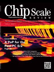
<strong>Sept</strong>-<strong>Oct</strong> <strong>2011</strong>Volume 15, Number 5The International Magazine for the Semiconductor Packaging IndustryThe International Magazine for Device and Wafer-level Test, Assembly, and PackagingAddressing High-density Interconnection of Microelectronic IC's including 3D packages, MEMS,MOEMS, RF/Wireless, Optoelectronic and Other Wafer-fabricated Devices for the 21st Century.Volume 15, Number 54<strong>Sept</strong>ember - <strong>Oct</strong>ober <strong>2011</strong>The Interconnect ChallengeTSV Interposers & 3D IC IntegrationAdvancements in Medical ElectronicsDesign-for-Test for 2.5D & 3DICsX-Ray Inspection for Counterfeit ICsInternational Directory of Defect Inspection Systems<strong>Sept</strong> <strong>Oct</strong>’s cover image depicts this issue’scontent on xray inspection with theinternational directory of defect inspectionsystems. Bill Cardoso provides a cuttingedge view of the technology behind CreativeElectron in the article “X-Ray InspectionTechniques to Identify Counterfeit ElectronicComponents”FEATURE ARTICLESThe Interconnect ChallengeScott Jewler, Powertech Technology, Inc.Automated Design-for-Test for 2.5D and 3D SICsErik Jan Marinissen, Mario Konijnenburg, IMEC and Sergej Deutsch, BrionKeller, Vivek Chickermane, Subhasish Mukherjee, Cadence Design Systemsand Sandeep K. Goel, TSMCTSV Interposers: The Most Cost-Effective Integrator for 3D ICIntegrationJohn H. Lau, Electronic & Optoelectronic Research Labs, ITRIElectronic Medicine: The Next Disruptive Medical TechnologyFrançois Berger and Ali Bouamrani, CEA-Leti Clinatec15182330<strong>Chip</strong> <strong>Scale</strong> <strong>Review</strong> <strong>Sept</strong>/<strong>Oct</strong> <strong>2011</strong> [<strong>Chip</strong><strong>Scale</strong><strong>Review</strong>.com] 1
<strong>Chip</strong> <strong>Scale</strong> <strong>Review</strong> <strong>Sept</strong>/<strong>Oct</strong> <strong>2011</strong> [<strong>Chip</strong><strong>Scale</strong><strong>Review</strong>.com] 3
4<strong>Chip</strong> <strong>Scale</strong> <strong>Review</strong> <strong>Sept</strong>/<strong>Oct</strong> <strong>2011</strong> [<strong>Chip</strong><strong>Scale</strong><strong>Review</strong>.com]
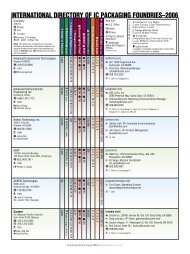
FEATURE ARTICLESX-Ray Inspection Techniques to Identify Counterfeit Electron ComponentsBill Cardoso, Ph.D., Creative Electron Inc.36DEPARTMENTSFrom the Publisher Recipe for SuccessKim Newman, <strong>Chip</strong> <strong>Scale</strong> <strong>Review</strong>Guest Editorial Automobiles Remain a Hotbed for Semiconductor MarketBrian Matas, IC InsightsIndustry News<strong>Chip</strong> <strong>Scale</strong> <strong>Review</strong> staffBig Market Player Makes a Big MoveFrançoise von Trapp, Sr. Technical EditorInternational Directory of Defect Inspection SystemsRon Molnar, Az Tech Direct LLCInterview Europe's OSAT Takes the Stage<strong>Chip</strong> <strong>Scale</strong> <strong>Review</strong> staffWhat's New in InspectionProduct ShowcaseAdvertiser Index, Advertising Sales6912284149525556<strong>Chip</strong> <strong>Scale</strong> <strong>Review</strong> <strong>Sept</strong>/<strong>Oct</strong> <strong>2011</strong> [<strong>Chip</strong><strong>Scale</strong><strong>Review</strong>.com] 5
VOLUME 15, NUMBER 5The International Magazine for Device and Wafer-levelTest, Assembly, and Packaging AddressingHigh-density Interconnection of Microelectronic IC'sincluding 3D packages, MEMS, MOEMS,RF/Wireless, Optoelectronic and OtherWafer-fabricated Devices for the 21st Century.<strong>Chip</strong> <strong>Scale</strong> <strong>Review</strong><strong>Chip</strong> <strong>Scale</strong> <strong>Review</strong><strong>Chip</strong> <strong>Scale</strong> <strong>Review</strong>6<strong>Chip</strong> <strong>Scale</strong> <strong>Review</strong> <strong>Sept</strong>/<strong>Oct</strong> <strong>2011</strong> [<strong>Chip</strong><strong>Scale</strong><strong>Review</strong>.com]Recipe for SuccessWe’ve always known we were on to something here at <strong>Chip</strong> <strong>Scale</strong><strong>Review</strong>, what with devoting our coverage to semiconductor devicepackaging; but there’s something very satisfying about seeing the rest of theindustry come to the realization that packaging is a vital value-add rather than justa necessary evil, and therefore worthy of its own publication. And if the number ofattendees, participants, sponsors and exhibitors registered for the <strong>2011</strong> Internationalheard industry-wide, loud and clear. Position your company in the direction of nextgenerationadvanced packaging and you can’t go wrong.At SEMICON West, I heard the term “contemporary packaging” used to refer toThese technologies currently satisfy 70% of the market because they fill the billfor low-cost, low-risk IC packages. But that appears to be changing as the growingsmart phone, tablet and cloud computing market intensify the need for higherperformance packages, even at an initially higher risk.Srini Sundararajan, packaging technology analyst for Oppenheimer, suggests thatthe technologies for manufacturing contemporary packages will soon be consideredcommodity techniques and while they’ll likely retain a 50% market share, the highestmargins will be realized by the tools, materials, and processes that serve the advancedpackaging segment (WLP, SiP, and 3D), which he predicts is likely to grow at 20%CAGR. He says these companies or vendors should see growth through 2015 at least,because these advanced packaging technologies are enabling in nature, and without them,smart phones and tablets requiring small sizes and form factors wouldn’t be possible.As Tien Wu of ASE so succinctly put it during his keynote address at SEMICONWest, it’s time to explore the new dynamics of the semiconductor business. He saidindustry veterans look at the industry and wonder, why are we still here, and what canwe do? How can we move forward? For the younger generation, the opportunity is ripefor diving into change; but where to begin? More than Moore has created an economicadvantage for the back-end. The front-end sees this and wants a piece of that pie as well.I take this all in, and wonder what it means for <strong>Chip</strong> <strong>Scale</strong> <strong>Review</strong>? We’vefocused on test, assembly and packaging since our beginnings; anticipating thetime when it would be the most exciting place to play. But how do we keep ourlegacy readers and advertisers engaged, while also keeping our content cuttingedge, and opening up opportunities for new readers and advertisers? Pleasing allpalates requires a delicate balance of the key ingredients, and as our team hasbeen putting together our 2012 Editorial Calendar, we think we’ve come up with arecipe that will appeal to everyone. Innovations in assembly, test, inspection, etc.of contemporary packages will always be a staple ingredient, accompanied by ahealthy dollop of WLP, SiP, and 3D integration, and with the usual smattering ofMEMS, and LED packaging for added spice. Bon Appetit!Kim NewmanPublisher
<strong>Chip</strong> <strong>Scale</strong> <strong>Review</strong> <strong>Sept</strong>/<strong>Oct</strong> <strong>2011</strong> [<strong>Chip</strong><strong>Scale</strong><strong>Review</strong>.com] 7
8<strong>Chip</strong> <strong>Scale</strong> <strong>Review</strong> <strong>Sept</strong>/<strong>Oct</strong> <strong>2011</strong> [<strong>Chip</strong><strong>Scale</strong><strong>Review</strong>.com]
Automobiles Remain a Hotbed for SemiconductorMarketBy Brian Matas, [IC Insights]In the classic 1964 movieGoldfinger, “Q” briefs JamesBond, the suave agent 007, on theoperation of his new specializedautomobile:“You’ll be using this Aston MartinDB5 with modifications. Now,pay attention please.Windscreen:bulletproof, as are the side and rearwindows. Revolving number plates,naturally, valid in all countries….”“Anything else?”“You see this arm here? Now openthe top and inside are your defensemechanism controls: smoke screen, oilslick, rear bulletproof screen, and leftand right front-wing machine guns.Now this one I’m particularly keenabout. You see the gear lever here?a little red button. Whatever you do,don’t touch it.”“Why not?”“Because you’ll release this sectionof the roof and engage and fire thepassenger ejector seat.”“Ejector seat? You’re joking.”“I never joke about my work, 007.”At one time or another, many of usprobably wanted to be James Bond anddrive exotic automobiles with all sorts ofgadgets and electronic wizardry. But, thefact is, today's “specialized” vehicles areequipped with enough sophisticated andpractical electronic systems to make “Q”and the 1960s-era James Bond envious.Without a doubt, the automobilemarket continues to be a hotbed forelectronic systems and the advancedsemiconductors that power them.Consumer preferences for comfort andconvenience along with governmentmandated safety and environmentalregulations have caused automakersto increase the number and qualityof electronics onboard new cars,which in turn, has resulted in a jumpin semiconductor content. Factorscontributing to this phenomenoninclude:Comfort/Convenience—Connectivityand onboard telematics areessential selling points for newcarshoppers who want to smoothlytransition content from their mediadevices to their cars, home, oroffice. Bluetooth technology isnow commonplace in cars, and Wi-Fi and center-stack displays thatreplicate the driver’s smartphonescreen, as well as onboard chargingpads for phones and portableelectronics will soon be standard.Performance—Electronics areused to optimize fuel consumptionand engine performance, andimprove vehicle traction control andstability. Electronics systems aretypically cheaper, safer, and morereliable alternatives to hydraulic- andmechanical-based systems, resultingin fewer vehicle recalls, fewer hitson warranty, and ultimately, greaterErgonomics/Safety—Airbags,anti-roll systems, lane departureand collision avoidance, automaticparallel parking, drowsy driversdetection, and emergency-callingsystems are now marketingtools. Meanwhile, interiors arethe next great frontier for designinnovation. Comfortable seating;creative, functional, and tastefullydesigned dashboards; and specificmood settings through lightingand aromas are being tested andwill likely be another area whereelectronics and semiconductorcontent will be applied.IC Insights believes the “trickledowneffect” of technology in carsis happening faster than originallyexpected. Sophisticated electronicsystems, which were the exclusivedomain of luxury-class vehicles afew years ago, have become morecommonplace in mid-range and lowerpricedautomobiles. This has caused ICInsights to raise its forecast for averagesemiconductor content per automobileto $350 for <strong>2011</strong>, a 15% increase fromthe $305 average in 2010 (see Figure1). Semiconductor content per vehicle isFigure 1. Average semiconductor content inautomobiles from 2008 and forecasted to 2014expected to average 9% annual growththrough 2014, increasing to $425 pervehicle at the end of the forecast period.The total automotive semiconductormarket is forecast to increase 12% in<strong>2011</strong> as new car shipments are forecast toincrease now that factories in Japan andsupply chains throughout the world havemostly recovered from the devastatingearthquake in Japan earlier this year.Semiconductor content per vehiclevaries based on factors such as the makeand model of the car and the region of<strong>Chip</strong> <strong>Scale</strong> <strong>Review</strong> <strong>Sept</strong>/<strong>Oct</strong> <strong>2011</strong> [<strong>Chip</strong><strong>Scale</strong><strong>Review</strong>.com] 9
Figure 2. <strong>2011</strong> Average Semiconductor Content per Car based on regionthe world where it is sold. In <strong>2011</strong>, theaverage semiconductor content per caris forecast to range from a high of $405in Japan to approximately $350 in NorthAmerica and Europe, to approximately$150 in the BRIC (Brazil, Russia, India,China) region, as seen in Figure 2.Automotive Applications-SpecificAnalog products (32%), AutomotiveSpecial Purpose Logic devices (13%),and 32-bit MCUs (14%) are forecastto be among the fastest-growing ICproducts in <strong>2011</strong>. Analog productsare used to gauge input functionslike speed measurement and enginemonitoring. Output functions suchas power windows, adjusting powerseats, controlling fuel injections, andignition timing require D-A converterscontrollers and power IC drivers.Mixed-signal logic ICs (analog anddigital functions on the same chip)are used in tire pressure monitoringsystems (TPMSs) and electronicstability control (ESC) systems—twoof the latest safety systems that willbe required for new cars sold in Japan,North America, and Europe. In Europe,tire-pressure systems will be requiredon all new cars sold after November 1,<strong>2011</strong>, and stability control systems willbe required on all new cars sold in theU.S. starting in 2012. These mandatedsystems will boost the need for varioussensors, analog, and mixed-signaldevices that will be needed to interpretthe information for the driver.In the important automotive marketsegment, 32-bit processing in MCUs isdriven by the advent of “intelligent” cardesigns and increases in sophisticated,real-time sensor functions forgovernment-mandated safety and crashavoidancesystems. In thenext few years, complex32-bit MCUs are expectedto account for over 25%of the processing power invehicles. MCUs with 32-bit processing cores aretypically found in driverinformation systems,enhanced safety features, and enginecontrol units that optimize real-timeperformance.Overall, the use of microcontrollersin cars is also expected to substantiallyincrease as more drivers turn to electricand hybrid-electric vehicles (HEVs).Hybrid vehicles use 32-bit MCUs tomonitor the need to switch betweengasoline engines and electric motorsin HEVs. This often requires complexsoftware and 32-bit processing as wellas large amounts of on-chip memoryand more I/O functions. More thana dozen MCUs are used to superviseelectrical-power boosting and batterystoragesystems inside electric andhybrid vehicles.In today’s models of high-end cars,up to 100 microcontrollers (8-, 16-, and32-bit devices) are used throughout thevehicle. This is more than six timesthe number of MCUs used in luxuryautomobiles in the 1990s. A growingnumber of luxury automobiles andhigh-end sports utility vehicles (SUVs)are offering automated “self-parking”options, which use dozens of sensors,controllers, and actuators that existin other automotive systems (such asantilock brakes, electronic steering,and collision avoidance). In the caseof Toyota’s Lexus LS460 sedan, thecar’s Advanced Parking GuidanceComputer communicates with 45 to 60other microcontrollers and embeddedcomputer systems attached to a 1Mb/scontrol area network (CAN) bus. Fordoffers an ultrasonic sensor-based ActivePark Assist option in its Lincoln MKSsedans and MKT luxury “crossover”utility vehicles as well as the EscapeSUV series. BMW, Volkswagen,and others are also designing parkassistand self-park features into theirvehicles. Meanwhile, a growing numberof automakers are hoping to expandon concepts used in early self-parkingoptions, advanced cruise controls, andcollision-avoidance systems to develop“smart” autonomous (driverless)vehicles over the next 10 years.Analog ICs and microcontrollers areforecast to account for the bulk of theautomotive IC market in <strong>2011</strong>, withlogic and memory ICs accounting formost of the remaining dollars (Figure3).The convergence of on-boardtechnologies that help navigate,calculate, and communicate importantFigure 3. <strong>2011</strong> Automotive IC Market by Device Type(Fcst, $18.6B)information to the driver will be akey factor in consumers’ decision topurchase a new car. Consumers havecome to expect certain safety features,are more aware of the impact of theircar on the environment, and havebecome dependent on being alwaysconnected to their social networks andthe Internet. More often, consumerswill reject products—including the carsthey drive—that do not match or enabletheir lifestyle.With the help of sophisticatedelectronics, automobiles have becomemore efficient, cleaner burning, andpacked with more safety systemsthan ever before. This will keep theautomotive IC market an active andvibrant market for semiconductors forthe foreseeable future.Brian Matas,VP, Market Research,IC Insights, can be reached at bmatas@icinsights.com10<strong>Chip</strong> <strong>Scale</strong> <strong>Review</strong> <strong>Sept</strong>/<strong>Oct</strong> <strong>2011</strong> [<strong>Chip</strong><strong>Scale</strong><strong>Review</strong>.com]
<strong>Chip</strong> <strong>Scale</strong> <strong>Review</strong> <strong>Sept</strong>/<strong>Oct</strong> <strong>2011</strong> [<strong>Chip</strong><strong>Scale</strong><strong>Review</strong>.com] 11
NEXX Systems Celebrates 10 Years of Yankee IngenuityBy Francoise von Trapp, Sr. Technical EditorAugust marked the 10thAnniversary of NEXXSystems, manufacturersof semiconductor equipment designedexpressly for wafer level packagingprocessing (WLP). The company,headquartered in Billerica MA,celebrated the milestone with acompany-wide barbeque that honoredfounder and former CEO Dick Post,and was attended by local dignitaries,friends and family of Post, suppliers,customers, and collaborative partners.Friends, colleagues, suppliers and customers gatherto celebrate NEXX’s 10th AnniversaryRezwan Lateef, VP of BusinessDevelopment, and Tom Walsh, CEOeach addressed the guests, talking aboutthe company’s accomplishments andfuture goals, and presenting Post withthe gift of a star named after him toacknowledge his vision and continuedguidance.Also a founding member of thecompany, Lateef recalled the day thecompany was first established with20 original employees, to the globalorganization it has now become with142 full time employees, 36 basedoutside the US, and 140 systemsinstalled at 40 companies. According toWalsh, the recent opening of the Chinato building local infrastructure globally,hiring direct sales personnel, and serviceand process engineers. Walsh explainedthat this is particularly important in Asiaand NEXX has already opened officesDick Post, NEXX founder, and Arthur Kiegler, CTO, talkabout the early daysin Taiwan and Singapore. He saidthe office in China posed a particularchallenge and should be considereda major accomplishment navigatingall the government regulations. Inaddition to addressing the company’saccomplishments, various speakersreminisced about working alongsideDick Post, and acknowledging hisvision for this company, includingArthur Kiegler, CTO and inventorof the company’s flagship, Stratuselectroplating system.Post himself humbly credited thecompany’s success thus far to thehiring of “smart people”. “You have toyou can do. Every hire must raise theaverage,” he noted. One of those hireswas his own successor. Walsh joinedthe company in 2009, hand-picked byPost to take the company to its nextphase of growth. “It’s hard to findsomeone who can take over and prettyseamlessly run this thing on up to thenext level. I guarantee you I can’t dowhat he’s doing. He gets to have thethrill of a Wall Street adventure,” hesaid.What’s Next for NEXXWalsh says he’s seen NEXXgrow from a company focused ondeveloping a process to one that ismore customer-driven in terms ofemphasis, although its entrepreneurialspirit remains the foundation of whatit is today.Robert Jackson, who joinedNEXX as VP and general manager ofelectrodeposition systems 10 monthsago, concurs with Walsh on NEXX’snext steps, and Walsh’s capability toguide them there. “What brought me toNEXX was the opportunity to work withTom Walsh again, move into an area ofsemiconductor plating with an emergingcompany in the packaging space,”he explained. “In the semiconductorindustry, the packaging space is growingmuch faster than the front-end, and thechance to take an emerging technologyand go through the process again withina growth industry was a really excitingopportunity. “Targeting the Wafer Level MarketWhat differentiates NEXX most fromits competitors, notes Walsh, is that itsproducts are designed specifically forthe wafer level packaging environmentJackson speaks of. Both the StratusECD and Apollo PVD systems haveunique architectures designed forWalsh says that older wire bondpackages are transitioning to flip chiptechnologies, and that the wirelessexplosion over the next 5-10 years willresult in a huge growth rates on thoseproducts.Commenting on packagingtechnologies in general, SriniSundurarajan, packaging technologyanalyst for Oppenheimer, saysadvanced packaging is one of the fewareas of technology that is likely to growat 20% plus CAGR, notes Sundararajan.“Companies or vendors that specializein tools that deal with next-generationadvanced packaging markets are likelyto see growth through 2015 at least”,12<strong>Chip</strong> <strong>Scale</strong> <strong>Review</strong> <strong>Sept</strong>/<strong>Oct</strong> <strong>2011</strong> [<strong>Chip</strong><strong>Scale</strong><strong>Review</strong>.com]
Rezwan Lateef, presents Post with the certificatefor his star, while Tom Walsh, CEO gives the star’scoordinateshe said, emphasizing that advancedpackaging technologies are “enabling”in nature. His viewpoint is that withoutthe enabling technologies, devices suchas smart phones and tablets that requiresmall sizes and form factors just wouldnot be possible or conveniently sized orpriced.Collaboration with SEMATECHWalsh also recognizes the importanceof R&D. “As CEO, I realize thatR&D is what fuels our engine. It isfundamental to our strategy whichis why we invest 17% of gross salesannual to continued R&D,” he stated,adding that since NEXX is still small,it’s necessary to reach out and developcollaborative efforts both in jointdevelopment projects with leadingcustomers, and with leading advancedpackaging research centers, such as theyhave with IBM and SEMATECH.NEXX Systems collaborateswith SEMATECH on innovativeelectrodeposition technology in thearea of advanced wafer-level packagingitems. According to Sitaram Arkalgud,director of SEMATECH’s 3D program,the collaboration with NEXX hasinvolved developing cost-effectivethrough silicon via plating solutionsfor member companies. He explainedthat each member company hasconsiderable input during all aspectsof the tool selection, evaluation andprocess development phases, and thatthe resulting technology is transferredback to those participating members –in this case, those in the 3D program.He says that the unique, modulararchitecture of the Stratus was animportant factor in the tool selection,since it provides SEMATECH withconsiderable flexibility, as well aspermitting high throughput and a lowcost-of-ownership in high volumemanufacturing.Walsh is excited about NEXX’s next10 years and says the industry shouldexpect to see some exciting new productintroductions in 2012. His intention is tocontinue exacting on the vision Post hadwhen he started NEXX, and to build onwhat began with “good old-fashionedYankee ingenuity, smart people, andhard work.”<strong>Chip</strong> <strong>Scale</strong> <strong>Review</strong> <strong>Sept</strong>/<strong>Oct</strong> <strong>2011</strong> [<strong>Chip</strong><strong>Scale</strong><strong>Review</strong>.com] 13
NANIUM and Georgia Tech Collaborateon <strong>Chip</strong>-last CommercializationNANIUM, Europe’s largest outsourcesemiconductor assembly and test(OSAT) provider, has become a SupplyChain Member of the 3D SystemsPackaging Research Center at theGeorgia Institute of Technology (GTPRC) Embedded MEMS, Actives andPassives (EMAP) Industry ResearchConsortium. As such, NANIUM willserve as package integrator for the newtechnology.The agreement is the foundation ofthe partnership, and the co-operationbetween the GT PRC and NANIUMis an example of the increase in globalindustry collaborations for GT PRC,providing a path for commercializationof System-on-Package (SOP) basedtechnologies.The incorporation of the EMAP <strong>Chip</strong>-Last embedding advancements willallow the extension of NANIUM’s fanouttechnology portfolio to SiP solutionsfor new applications and markets,including Interposers.GLOBALFOUNDRIES and Amkor toCollaborate on Advanced Assemblyand Test SolutionsGLOBALFOUNDRIES and AmkorTechnology, Inc. have entered into astrategic partnership to co-developand commercialize integrated fabbump-probe-assembly-testsolutions.Through the partnership, Amkorwould become a founding memberof GLOBALFOUNDRIES’ GlobalAlliance for Advanced AssemblySolutions, designed to accelerateinnovation in semiconductorinterconnect, assembly and packagingtechnologies.By joining forces, the companies saythey plan to extend the ecosystem toaddress growing market needs, whilebolstering their ability to deliver end-toendsolutions for customers at advancedtechnology nodes. Additionally, thecompanies have amended an existinglicense agreement to expand their leadfreewafer bump licensing relationship.As the industry moves aggressivelyto more advanced technology nodes,innovation in interconnect, assemblyand packaging solutions is becomingincreasingly important. Supply chainmanagement has become a criticaltopic. The partnership betweenGLOBALFOUNDRIES and Amkor isexpected to enable the supply chain tobetter meet these diverse requirementsand deliver robust and reliable solutionsto mutual customers.Assembleon Enters the SemiconductorMarketAssembleon, tool manufacture for thesurface mount industry, has entered thesemiconductor back-end market with thelaunch of its A-Series Hybrid, a singletool used for high speed, high accuratedie placement and shooting. Highparallel placement technology targetsSystem-in-Package (SiP) and Multi<strong>Chip</strong> Module (MCM) manufacturing asAccording to Patrick Huberts,program manager for the A-SeriesHybrid, different pieces of equipmentare currently used in the industry toplace chips and known good dies (KGD)for manufacturing SiP, MCM andhigh performance flip chip modules.Assembleon’s solution puts all theprocesses on a single machine, forreduced production and investmentcosts, explains Huberts.Tool features includeprogrammable force control, afluxer dip station and high accuracycameras. The tool can reportedlybond flip chips at a repeatabilityof 10μm while placing at a recordspeed of 2,500 components per hour(cph) per single placement head. Diebonding speeds are 3,500cph perhead at 25μm. The company claimsthat this first-of-its kind tool achieves99.99% yields, avoids the risk ofcracked components, and eliminateswaste, rework and defective endproducts.NxGen Electronics Names Tri LePresidentNxGen Electronics, provider ofmicroelectronic packaging solutions andproduct innovations, has appointed TriLe as president.Tri has managedengineering andoperations teamsat NxGen forthe past 6 years,promoting acustomer focusedstrategy within the company, leadingNxGen to engage in collaborativecommercialize NxGen’s IP.“Tri has expertise in buildingand leading teams through complexdevelopment programs that requirecoordination of marketing and businessdevelopment, and (the electrical,mechanical and software) engineeringservices we offer”, said Chairman andCEO, Art Fillmore.Prior to joining NxGen, Tri servedas an Optoelectronic Packagingengineer at Peregrine Semiconductor,a startup company specializing in RFCMOS solutions. He also previouslyheld technical positions at TRW(now Northrop Grumman). Tri holdsa Bachelor in Engineering and anExecutive MBA from Anderson Schoolof Management at UCLA specializingin Entrepreneurship.Dennis P. McGuirk Named Presidentand CEO of SEMISEMI has appointed Dennis“Denny” P. McGuirk as president andCEO, effectiveNovember 14,<strong>2011</strong>. McGuirksucceeds StanleyT. Myers, wholed SEMI forthe past 15 yearsand has servedon its board of(continued on Page 53)14<strong>Chip</strong> <strong>Scale</strong> <strong>Review</strong> <strong>Sept</strong>/<strong>Oct</strong> <strong>2011</strong> [<strong>Chip</strong><strong>Scale</strong><strong>Review</strong>.com]
The Interconnect ChallengeBy Scott Jewler, [Powertech Technology, Inc.]Those of us in the semiconductorindustry, as well as the rest ofthe world’s population as a whole havecome to expect nearly magical increasesin the computing, communication,and entertainment capability of theelectronic devices we use at shortand regular intervals. Powered by thepractical application of Moore’s law andthe endless imagination of engineers,designers, and product managers, inone generation we’ve seen the noveltyof a personal computer booting upon an eight inch operating disk andrunning a user-written Fortran programtransformed into ubiquitous mobilephones, smart phones, tablets and othercomputing devices that touch the livesof over a quarter of the population ofthe planet in a meaningful way.Those of us working in packagingand assembly can take some pride inour contribution to this incredible paceof advancement. Technologies such asplastic encapsulation, surface mounttechnology, area array packaging, ‘chipscale’ packaging, die and packagingstacking and related technologies allhelped enable silicon functionality intosmaller end products.In terms of first-level interconnectbetween devices, however, thecontribution of back-end technology hasbeen less transformative. We developedaluminum, then gold, then copper wirebonding technology. We developedto mainstream high volume nearly 30years later.Mapping the IndustryAs we look towards mapping thefuture needs of the electronics industry,and how interconnect must evolveto enable the industry to continuedelivering the level of innovation nowexpected by the market, some guidingassumptions are clear. Planer scalingof transistors, the fundamental driverof the last 50 years of semiconductoradvancement, is getting more expensiveboth in terms of fabrication and designcosts. Practically, this means fewerhigh-volume device types will be ableto take advantage of smaller fabricationgeometries. With multiple low-powerprocessing cores, the next generation ofhigh-performance logic devices will nodoubt be able to calculate, process, andmanage incredible amounts of data. Thisputs the next generations of incredibleuser experiences tantalizingly close athand. The challenge for interconnecttechnology is how to get all these dataand signals out of these super chips andturn them into something we analoghumans can use to communicate,calculate, or entertain ourselves. This isthe interconnect challenge.The Interconnect TechnologiesSeveral new interconnecttechnologies are gradually entering themarket to address these challenges.Disruptive to the existing infrastructureand semiconductor packaging supplychain, many conflicting points of viewand predictions about the future of thesenew interconnection technologies areseen in trade media, conferences, andcommercial discussions.Copper pillar bumping is the firstof this next generation of interconnecttechnologies to reach high volumemanufacturing (HVM) (Figure 1).Although limited now to a few CPUand application processor applications,Figure 1. Copper Pillar BumpFigure 2. Through Silicon Viascopper pillars are a critical technologyfor higher interconnect densities andfaster data communications speeds.Through silicon via (TSV) is the nextinterconnect technology to move tovolume production (Figure 2). Used inimage sensors today to provide efficientinterconnect between sensor and driver,TSV as an interconnect technology that isstill generating more papers and articlesthan live applications. Like the ball gridarray (BGA) in the late ‘90’s, this situationcould change in a short period of time.Micro bumps using copper pillarsand TSV are key enablers for anotheremerging new interconnect technology,silicon interposer integration. Siliconinterposers (sometimes inscrutably referredto as 2.5D), enable fine-pitch high-speedconnections between independent chips(Figure 3). They can also be used to fanout high density connections from thescale and pitch of a chip to the geometrythat can be cost effectively managed atboard level assembly.Figure 3. Silicon Interposer<strong>Chip</strong> <strong>Scale</strong> <strong>Review</strong> <strong>Sept</strong>/<strong>Oct</strong> <strong>2011</strong> [<strong>Chip</strong><strong>Scale</strong><strong>Review</strong>.com] 15
Figure 4. 3DICThe emerging technology beingmost hotly debated is stacking ofactive die using TSV and micro bumpinterconnect technology (Figure 4).Widely referred to as 3DIC (a name thathas created significant confusion withother vertical technologies includingFinFET transistors, stacked transistors,conventional stacked IC’s with wirebondand flip chip interconnect, and stackedpackages with solder interconnect),stacking of active devices using TSVinterconnect offers the possibility ofincredibly dense functional integrationwhile generating a host of technical andcommercial concerns and debate.Micro Interconnect with CopperPillar BumpsIn addition to improved thermaland electrical performance, copperpillar bumps provide higher standoffand better coplanarity than solderbumps as pad pitches decrease. Theseattributes in turn allow for substrateswith smaller capture pads, freeing uprouting channels and reducing substratefabrication costs.Design and package selection fora host of new products are takingadvantage of these features to improveperformance while reducing costsover prior solutions. In logic ICs, bothperimeter and area array design usingcopper pillars can offer advantages.With current capabilities of bumpingpitches down to 40 to 50μm, perimeterpad layouts can access the electricalperformance and space savings offlip chip over conventional wire bondwithout driving up substrate costssignificantly. Area array designs fromaround 90 to 150μm can similarlyutilize copper pillars instead oftraditional solder bumps to achievehigher assembly yields with lowercost substrates. Graphic and DDR3DRAM are beginning to convert tothis technology as well. By optimizingdesigns around substrate manufacturingequipment accuracy; improved electricalperformance over wire bonding can bemanufacturing cost.Controlled standoff, fine pitch,and excellent thermal and electricalperformance make copper pillars theinterconnect technology of choicefor the emerging micro interconnectrequirements for active and passivedevice stacking combined with TSV.Through Silicon ViaWith market applications currentlylimited primarily to CMOS imagesensors, TSV certainly qualifies asthe most talked about and potentiallytransformative new interconnecttechnology in the industry. Numerousmethodologies to form, insulate, andmetalize vias through silicon are beingdeveloped and demonstrated. Slowlybut surely questions about via geometry,keep-out zones, cost, and reliability arebeing answered.TSVs can be formed in siliconsubstrates with only passive metalinterconnect creating siliconinterposers. They can also be createdin active integrated circuit devicesto create very short and electricallyefficient interconnect between devicesstacked vertically.In via-middle technology, vias aregenerally formed in the front-end fabmiddle-of-line or contact metallizationprocess. These vias are later exposedthrough back-side wafer thinning inwhat is typically thought of as back-endor assembly middle-of-line. The viasmust be exposed without contaminatingthe surrounding silicon area with copper.Once exposed, they must be prepared toaccept bumps for interconnect to otherdevices or interposers.In via-last technology, full thicknesswafers are typically shipped from thefront end wafer fab. After front sidebumping and attachment to a supportsystem, the wafers are thinned and viasformed from the backside. Similar to thevia-middle process, the exposed vias arethen bumped to prepare for interconnectto other devices or interposers.Silicon InterposersSilicon interposers typically includedmultiple layers of metal routing, TSVs,and top and bottom side bumping.They have multiple uses includingfanning out ball pitch of high-pincountsmaller devices to matchsubstrate manufacturing technologyand providing high-speed interconnectbetween processors and memory orother logic chips for network andcomputing applications.Although there are some potentialapplications for Si interposers withgreater than 10μm metal line widths,the majority of new applications appearto require 2-3 layers of 2-3μm lines ina non-organic insulator. To complete aninterposer, TSV and top and bottom sidebumping must also be completed.For this reason the silicon interposersupply chain is still emerging. Themetallization process is commonlyfound in wafer fabs however most ofthese facilities do not provide via-lastor bumping capability. OSAT bumpinghouses may have the bumping or evenTSV formation capability, but probablylack the fine-pitch Cu damasceneprocesses required to create multipleAlthough a few exceptions may exist,the initial production of Si interposerswill likely be most economical throughcollaboration between front-end andback-end service providers.3DICStacking ICs using wirebond or acombination of FC and wirebond hasbeen widely practised for over 10 years.In today’s most common communicationand computing devices, stacks of 4 – 8die with individual die thicknesses ofless than 50μm are in very wide usage.Die sorting and assembly technologyadvancements have enabled thesememory stacks to yield finished partsat extremely high yield, making themnot only excellent performing but cost-16<strong>Chip</strong> <strong>Scale</strong> <strong>Review</strong> <strong>Sept</strong>/<strong>Oct</strong> <strong>2011</strong> [<strong>Chip</strong><strong>Scale</strong><strong>Review</strong>.com]
Figure 5. Common 9 die stack memoryFigure 6. Groundbreaking and construction of PTI’snew 750,000 Sq Ft. Copper Bump and TSV Facility ineffective solutions.Many argumentsagainst 3DICs areovercome by takingas an example ahomogeneous stackof memory IC similarto Figure 5. Usingprobable good die(PGD), thin diehandling, cumulativeyield loss, and thesupply chain modelare similar betweenwire bond and 3DICsolutions.The big questionsare cost and yield ofthe TSV interconnecttechnology. Whenconsidering TSV cost,it’s helpful to recognizethat unlike traditionalpackage assembly,where material coststhat are fully variablewith volume constituteover 50% of the totalassembly cost, in TSV,fixed assets in theform of PVD, DRIE,ECD, and other toolswill form the majorHsinchuportion of cost. Given that, the path to low cost-of-ownership onthese types of tools is higher throughput; the key to driving cost ofTSV will be volume. Small players testing the waters will not becompetitive with those who invest in volume manufacturing.ConclusionsWhile packaging has delivered many innovative solutionsto improve silicon function density over the years, the cost ofcontinuing the path of Moore’s Law creates new and compellingchallenges. Among them, core packaging technologies have seenCopper pillar bumps, TSV, silicon interposers, and 3D ICtechnologies are entering the market and will be critical to meetthe future needs of the industry. Memory devices will be amongtechnologies. With high volumes and fast ramp cycles, theseapplications will be able to quickly drive scale and manufacturingefficiency leading to competitive costs and yields. Otherapplications will surely follow.Scott Jewler, Chief Engineering, Sales and Marketing Officer,Powertech Technology can be reached at scottjewler@powertech-usa.com.<strong>Chip</strong> <strong>Scale</strong> <strong>Review</strong> <strong>Sept</strong>/<strong>Oct</strong> <strong>2011</strong> [<strong>Chip</strong><strong>Scale</strong><strong>Review</strong>.com] 17
Automated Design-for-Test for 2.5D and 3D SICsBy Erik Jan Marinissen, Mario Konijnenburg, [IMEC], Sergej Deutsch, Brion Keller, Vivek Chickermane, Subhasish Mukherjee,[Cadence Design Systems], Sandeep K. Goel, [TSMC]With the advent of 2.5D and3D stacked ICs (SICs)based on through silicon vias (TSVs), itis imperative to prepare for testing suchproducts for manufacturing defects. Themain test challenges for SICs are relatedto test flows, test contents, and testaccess.Test FlowsSICs offer many stages to performmanufacturing test than conventionalchips, which typically are only subjectto one wafer test (‘e-sort’) and onedistinguish:Pre-bond test: before stacking, oneither original thick wafers and/oron thinned-down wafers.Mid-bond test: during the stackingprocess, i.e., when a partial stack isformed.Post-bond test: when the stack iscomplete.Final test: after packaging thecomplete stack.The challenge is to optimize the testflow as an integral part of the overallcosts as low as possible. This requirescost modeling of parameters such aswafer cost, die size, die yield, stackingprocess (D2W or W2W), stackingyield, test coverage, test cost, andpackage cost. Modeling results showthat more testing will increase the testcost, but typically reduce the overallproduction costs. 1 Also, a cost-optimaltest flow typically evolves over time,as production processes mature andyields increase, which in return requiresTest ContentsThe dies being stacked are builtwith regular process technologies,suffer from all conventional (CMOS,DRAM) defects, and hence requireall well-known tests: stuck-at faults,transition faults, delay faults, verylowvoltage tests, leakage currents,etc. 3D processing steps, such as waferthinning, effect device performance, butare not already covered by conventionaltest suites. The only structures thatrequire our attention with respect to testpattern generation are the new TSVbasedinterconnects. The possibilitiesfor testing TSVs prior to stacking arelimited, and at that stage the actualinterconnect (typically in the form ofmicro-bumps on top of the TSVs) hasnot been formed yet. Hence, the TSVbasedinterconnects are best tested aspart of a mid- or post-bond test. Theyrequire a dedicated interconnect faultmodel and corresponding automatic testpattern generation (ATPG) engine.Test AccessSICs present various challengesrelated to test access, such as the abilityto pump in test stimuli and pump out testresponses from the die-/stack-under-test.For performing pre-bond tests, all nonbottomdies of the stack only have “TSVI/Os”; these small micro-bumps comein pitches much smaller and array sizesmuch larger than what can be handledby today’s conventional probetechnology. The probe industry isworking hard to enable probingon fine-pitch micro-bumps, withJEDEC’s upcoming Wide I/OSpecification (JEDEC 42.6) formajor target. 2 However, until thisfine-pitch probe technology isproven mature, chip makers areputting additional dedicated probepads on their non-bottom dies toenable pre-bond testing.Another challenge is posed bystack-internal test access. Afterstacking, test access from the testequipment (either through probingor, after packaging, via a test socket)is through the external I/Os of the SICproduct, which are located in the bottomof the package; these signals musttravel through the bottom die. Designfor-test(DfT) circuitry is required inall the dies comprising the stack topropagate test instructions and data upand down through the stack. Testing theTSV-based interconnects between twoadjacent dies requires DfT that providescontrollability and observability onboth ends of the interconnect. To gettest data higher up in the stack, DfT inthe dies below it needs to propagate teststimuli coming from the test equipmentupward in the stack, and, vice versa, testresponses downward.3D-DfT ArchitectureIMEC has developed a 3D-DfTarchitecture that meets the aboverequirements. 3,4 It enables a modulartest approach, in which dies, theirembedded IP cores (if any), and TSVbasedinterconnect layers can be testedas stand-alone units. This modular testapproach allows for test contents to betailored to the manufacturing processesof various dies and provides yieldFigure 1. Overview of the 3D-DfT architecture based on dielevelwrappers18<strong>Chip</strong> <strong>Scale</strong> <strong>Review</strong> <strong>Sept</strong>/<strong>Oct</strong> <strong>2011</strong> [<strong>Chip</strong><strong>Scale</strong><strong>Review</strong>.com]
tests will use the Serial TAM for testinstructions and the Parallel TAM for testdata, as it provides higher test throughputand hence shorter test times. Once theSIC is soldered onto a board, board-levelinterconnect testing and in-chip debugwill typically use the Serial TAM, whichis then connected to the IEEE Std 1149.1(“JTAG”) TAP pins.The stacked dies’ Serial and ParallelTAMs are daisy-chained up in the stackand back down again. Every die can beinstructed to be in either a TestTurn orTestElevator mode; the TestTurn modedirects the TAM downward from thisdie on, while the TestElevator modecontinues to involve the next-higherdie in the TAM. This allows the testFigure 2. Schematic implementation of the 3D-DfTdie wrapperinclusion, exclusion, and various moduletest scheduling to support multiple testmanufacturing yields mature over time.The main component of the 3D-DfTarchitecture is a die-level wrapper. Thethe existing conventional DfT in the dieitself (Figure 1). The 3D-DfT wrapperbuilds on and extends well-known DfTstandards such as IEEE Std 1149.1 (forboard-level interconnect testing) andIEEE Std 1500 (for embedded IP cores).Each wrapper has a well-specified testinterface at its bottom side, consistingof a serial interface for test instructionsand test data, and an optional parallelinterface (of scalable width) for (highbandwidth) test data. On the top sideof the die, a mirror-copy of that testinterface exists for each other die thatwill be stacked directly on top of it. Inother words, for a top die, no such toptest interface will exist; for a middle diein a single-tower stack, exactly one suchtop test interface will exist; and for abase die in a multi-tower stack, multipletop test interfaces will exist, one for eachtower.Serial (one-bit) and Parallel (n-bit)Test Access Mechanisms (TAMs)comprise the test interfaces. The SerialTAM handles both test mode instructionsand serialized test data. The optionalParallel TAM carries parallel test data.In a typical use scenario, semiconductormanufacturers that perform pre-bond,mid-bond, post-bond, and/or final<strong>Chip</strong> <strong>Scale</strong> <strong>Review</strong> <strong>Sept</strong>/<strong>Oct</strong> <strong>2011</strong> [<strong>Chip</strong><strong>Scale</strong><strong>Review</strong>.com] 19
Figure 3. EDA tool flow for die makersFigure 5. Screen shot from our EDA tool setFigure 4. EDA tool flow for stack makersengineer to flexibly configure his/hertest access path in the stack. Each diecan be instructed to be in one of threetest modes: Intest, Extest, or Bypass.In Intest mode, the die’s internals aretested, and its internal DfT infrastructureis included in the TAM. In Extest mode,the die’s external connections are tested,i.e., the TSV-based interconnects toanother die. In Bypass mode, the die isnot testing at all, but simply propagatesthe TAM data, typically to and fromanother die-under-test.If a probe solution is available formicro-bumps, these I/Os can be usedfor pre-bond testing. This depends onthe actual diameter, pitch, and arraysize of the micro-bumps and the match(or mis-match) to the available probetechnology. If pre-bond probing onmicro-bumps is impossible, the 3D-DfTarchitecture provides the option to equipthe die with additional dedicated probepads. A dedicated mode of operationenables test access via these pre-bondprobe pads. As dedicatedprobe pads bring significantadditional area costs, chipdesigners might want to restricttheir number to be less thanthe number of TSV-based I/Os. This 3D-DfT architectureis prepared to handle differentwidths for the Parallel TAM forpre-bond and post-bond cases,off between test bandwidth andcorresponding test time on onehand, and cost of additionalpre-bond probe pads on theother hand.A Wrapper Instruction Register (WIR)controls the test mode of a die. Uponreset, this WIR brings the die into itssafe functional mode of operation. TheWIRs of the various stacked dies aredaisy-chained and can be programmedby the test engineer by shifting ininstructions via the Serial TAM. Thisgives the test engineer the flexibilityto include, exclude, or re-order testsat will at every stage of the test flow.For example, in a stack of three dies,it would be possible to test all diessequentially, followed by a simultaneoustest of all inter-die interconnects: Die1; Die 2; Die 3; Intc 1-2 || Intc 2-3.Alternatively, it would also be possibleto test Dies 1 and 2 simultaneously,Die 3, and then the second interconnectlevel: Die 1||Die 2; Intc 1-2; Die 3; Intc2-3.Figure 2 shows a schematicimplementation of a 3D-DfT wrapperfor a die in the middle of a stack. It hasfunctional and test ports toward thenext-lower die shown on the left, andfunctional and test ports toward thenext-higher die shown on the right. Ithas a Wrapper Serial Control (WSC),a Serial TAM (consisting of WrapperSerial In (WSI) and Wrapper SerialOut (WSO)), and a n-bit wide ParallelTAM (consisting of Wrapper ParallelIn (WPI) and Wrapper Parallel Out(WPO), shown as fat lines). Also clearlyvisible in Figure 2 are the mirrored testinterface at the top side of the die, andthe (optional) additional probe pads forpre-bond testing.EDA Tool SupportCadence Design Systems has workedwith IMEC to implement and supportthe described 3D-DfT architecture withtheir design automation tools. This ledfor die makers, the second one for stackmakers that use the dies as buildingblockcomponents; these flows areshown in Figures 3 and 4 respectively.The light-blue boxes show the specificsolutions for DfT insertion and testgeneration. The gray boxes represent thedenote other (non-test) EDA steps,dark-gray boxes represent physicalis the ability to perform a test.The flow for die makers starts withof the die in question. A 3D-DfTwrapper is added to this die design withdedicated scripts for the synthesis tool20<strong>Chip</strong> <strong>Scale</strong> <strong>Review</strong> <strong>Sept</strong>/<strong>Oct</strong> <strong>2011</strong> [<strong>Chip</strong><strong>Scale</strong><strong>Review</strong>.com]
Encounter RTL Compiler. 5 The userneeds to specify whether or not this isa bottom die that needs to implementIEEE Std 1149.1, the various (optional)instructions and corresponding op-codesthat he/she wants to have implementedin the WIR, and the widths of pre-bondand post-bond Parallel TAMs. After aDfT rule check, the die can move onto physical design (layout) and wafermanufacturing. A next step would beautomatic test pattern generation (ATPG)with Encounter test. Several sets of testof the DfT (through pattern simulation),for pre-bond testing by the die maker,and for die Intest by the stack maker.In case the die maker does not want todisclose the full design details of thedie with the stack maker, EncounterTest is able to generate a so-called ‘skinmodel’; this is an abstract version ofthe die design, which includes all that isnecessary for testing this die as part ofan SIC, but excludes internal design IP.The skin model allows the stack makerto generate his/her own interconnect(Extest) patterns, but for testing the dieitself, he/she will depend on 'migrateablepatterns', which can be preparedby Encounter test. In case the die makerdoes not mind disclosing the full designdetails of the die to the stack maker,migrate-able Intest patterns and skinmodel are not required and the full netlistof the die suffices; However, becausethe skin model contains just the logicnecessary to run the external boundaryscan interface, it allows for a muchsmaller gate-count model for the SIC.The outputs of the various dies thatpresumably go through the die makerflow become the inputs in the stackmaker flow. In Figure 4, it is assumedthat the various die makers want tohide their design details from the stackmaker. Hence, for each die in the stack,the stack maker gets the physical die,migrate-able Intest patterns for that die,and an abstract skin model for the die.The first action for the stack maker isto do the functional stack design (andverification), i.e., setting the order andconfiguration of the dies in the stack.In practice, this will typically be doneeven before the various die makers starttheir efforts. The synthesis tool has theability to automatically interconnect the(Serial and Parallel) test ports of variousdies in the stack. The resulting stacknetlist is complemented by either thefull netlist or the skin model of each die.This combination is used in EncounterTest for both Intest migration andinterconnect-ATPG. Intest migrationtakes the Intest test patterns as deliveredby the die maker, and translates themfrom a test defined at the die I/Os toa test defined at the SIC I/Os. Thistranslation takes into account the test<strong>Chip</strong> <strong>Scale</strong> <strong>Review</strong> <strong>Sept</strong>/<strong>Oct</strong> <strong>2011</strong> [<strong>Chip</strong><strong>Scale</strong><strong>Review</strong>.com] 21
data transportation through Elevatormodes of dies lower in the stack andthe corresponding required instructionsettings for that. This procedure isrepeated for the Intests of all dies in thestack. Interconnect-ATPG generatesExtest test patterns that cover faultsbetween the various dies in the stack.These patterns can be simulated forneed to be put in a test schedule andapplied to the SIC which is made up ofthe stacked physical dies.ResultsA test chip design from TSMC wasone of the first vehicles on whichthe tool flow was demonstrated. Thecircuit in 65nm CMOS technology wassmall and I/O rich. The die design wasextended with a 3D-DfT wrapper, and,assuming it was the bottom of a diestack, also IEEE Std 1149.1 hardware.The correct operation of this test chipchecking and pattern simulation. Thegate area DfT overhead for this designwas 8.4% for plain scan insertion andJTAG circuitry, and an additional 1.1%for the 3D-DfT wrapper. Note that therelative 3D-DfT area will scale downfurther for larger, more realisticallysizeddesigns. In addition to these gatearea costs, there are area costs for JTAGpads and pre-bond probe pads.The first hardware demonstratorprototype of the 3D-DfT architecture iscurrently being developed.2.5D- and 3D-SICs might contain diesfrom various die makers. For testing SICswith dies from heterogeneous sources, itis important that the DfT infrastructure inthe various dies is compatible. This willrequire standardization of the DfT, suchthat compliant dies contain a feature setthat guarantees a minimum set of interoperableDfT structures. Specificallytoward this goal, the IEEE 3D-TestWorking Group is developing the P1838standard, and our 3D-DfT architecturehas been proposed to this WorkingGroup. 6References[1] M. Taouil et al., “Test Cost Analysisfor 3D Die-to-Wafer Stacking”,Proceedings of IEEE Asian TestSymposium, December 2010, Shanghai,China, pp. 435-441.[2] K. Smith et al., “Evaluation ofTSV and Micro-Bump Probing forWide I/O Testing”, Proceedings ofIEEE International Test Conference,<strong>Sept</strong>ember <strong>2011</strong>, Anaheim, California.[3] E.J. Marinissen et al., “A Structuredand Scalable Test Access Architecturefor TSV-Based 3D Stacked ICs”, IEEEVLSI Test Symposium, April 2010,Santa Cruz, California, pp. 269-274.[4] E.J. Marinissen et al., “3D DfTArchitecture for Pre-Bond and Post-Bond Testing”, Proceedings of IEEEInternational 3D Systems IntegrationConference, November 2010, Munich,Germany.[5] S. Deutsch et al., “Automation of 3DDfT Insertion”, Proceedings of IEEEAsian Test Symposium, November<strong>2011</strong>, New Delhi, India.[6] 3D-Test Working Group, http://grouper.ieee.org/groups/3Dtest/ .Erik Jan Marinissen, Principal Scientist atIMEC can be reached at mariniss@imec.be22<strong>Chip</strong> <strong>Scale</strong> <strong>Review</strong> <strong>Sept</strong>/<strong>Oct</strong> <strong>2011</strong> [<strong>Chip</strong><strong>Scale</strong><strong>Review</strong>.com]
TSV Interposers: The Most Cost-Effective Integratorfor 3D IC IntegrationBy John H. Lau, [Electronic & Optoelectronic Research Labs, ITRI]3D integration consists of3D IC packaging, 3D ICintegration and 3D Si integration.It is the presence of through siliconvia (TSV) — or lack thereof — thatseparates 3D IC packaging from 3DIC/Si integrations, since the latter twouse TSV but 3D IC packaging doesnot. TSV 3D integration involvesstacking thin chips with microbumpswhile 3D Si integration refers to thinwafer stacking without bumps (i.e.,bumpless). In 3D IC integration theTSVs can be made by using either viafirst, middle, or last methods, whilefor 3D Si integration the TSVs canbe made before bonding if Cu-to-Cu method is used or after bondingif SiO 2 -to-SiO 2 method is used. TheTSV diameter for 3D Si integrationfilling material for 3D IC integrationis usually copper and is fabricatedby electroplating, while for 3D Siintegration is either tungsten or copperby physical vapor disposition (PVD).In the next 10 years, high volumeproducts with 3D Si integration,will exist in niche applications. Butultimately 3D Si integration is theright way to go and compete withMoore’s law. In the mean time, 3D ICintegration offers a compelling andcost effective stepping stone and more.Memory-<strong>Chip</strong> StackingBasically, there are two groups of3D IC integration; one is memory chipstacking and the other uses interposers(active and passive). Unfortunately,due to cost issue and competingtechnologies, e.g., Au/Cu wirebonding, memory-chip stacking is notin volume production today.Active InterposersTSVs can be used as active interposerssuch as logics and microprocessors. Forexample, Samsung has proposed a wideI/O DRAM in which the master chip isthe active interposer. However, due tothe high device density and complexityof the circuits on the CPU and logicchips, finding places/spaces to “drill”holes (TSVs) either by via-middle orvia-last processes are very difficult.Additionally, the CPU (or logic chip)and memory chip sizes and numberof pin-outs may differ. Forcing themto attach reduces design freedom andcould compromise functionality. Thus,for active interposers, we have to waitfor the ecosystem and EDA, except forsome companies with both memoryand logic technologies/capabilities andniche applications such as CMOS imagesensor (CIS), 3D MEMS, and 3D LEDs.Passive InterposersThe biggest issue with 3D ICintegration using active interposersfor system houses is the “businessmodel”. Companies buy the chipsfrom different sources and want themto be “bullet-proof” before they areshipped to theOSATs. Forcingtwo chipsfrom differents o u r c e stogether into“one chip” isnot acceptableto the systemhouses becauseif somethingwrong, theydon’t know who is responsible forfinding the root causes and fixing theproblem so they can quickly shippingtheir products again.Using a passive interposer tointegrate a few “bullet-proof” chipstogether is what the system housesprefer. Thus, passive interposerbecomes the most effective and lowcost 3D IC integrator, as it eliminatesthe need to fabricate TSVs intoactive dies. Additionally, there is noneed to thin and metalize the activedies. Furthermore, there’s no need totemporary bond and subsequently debonda supporting wafer to the activewafers. In this scenario, the passiveinterposer is the workhorse of our 3DIC integration SiP before the 3D Siintegration time comes.Passive Interposers Used asSubstrates (2.5D Integration)There are two kinds of passiveinterposers; one is 2.5D IC integration(Moore's Law chips on the interposer’stop side) and the other is 3D ICintegration (Moore's law chips on bothsides of the interposer).Figure 1 shows ITRI’s test vehiclefor the study of its electrical, thermal,and mechanical performances. Thestacked, one thermal chip, and onemechanical chip. It is over-moldedFigure 1. TSV interposers used as substrates: ITRI’s Phase-I 3D IC integration testvehicle. Updated from [IEEE/ICEP (<strong>2011</strong>)]for pick-and-place purpose as wellas to protect the chips from harshenvironments. There are RDLs andstress sensors on the interposer’s topand bottom sides. Also, integratedpassive devices (IPDs) are fabricatedinterposer (12.3mm x 12.2mm).<strong>Chip</strong> <strong>Scale</strong> <strong>Review</strong> <strong>Sept</strong>/<strong>Oct</strong> <strong>2011</strong> [<strong>Chip</strong><strong>Scale</strong><strong>Review</strong>.com] 23
Figure 2. Semi-Embedded TSV interposer with stress relief gap. Note: underfillbetween the chips and TSV interposer and the chips and organic substrate/PCB isnecessaryThis test vehicle can be degeneratedto the case of: wide I/O DRAM ifthere are not mechanical and thermalchips and the interposer is an ASIC;wide I/O memory if there is not thememory-chip stacking nor the TSVsin the mechanical/thermal chips andthe interposer is either an ASIC ormicroprocessor; and wide I/O interfaceif there is not the memory-chipstacking and there are not any TSVsin the thermal/mechanical chips. Thus,the enabling technologies developedwith this test vehicle can have verybroad applications.Figure 2 shows a semi-embeddedTSV interposer with a stress reliefgap. The design is low profile andfree to use of any Moore's law chipwithout TSVs, which results in a shortdesign cycle with low manufacturingcost. Additionally, RDLs allow chipsto talk to each other at short distance.Many TSVs can be used for power andground. This design is very reliablebecause the stress relief gap reducesthe thermal expansion mismatchbetween the embedded interposer (6 –8x10 -6 / o C) and the organic substrate/PCB (15 – 18.5x10 -6 / o C).Passive Interposers Used asStress Relief (Reliability) Buffersfor Moore’s Law <strong>Chip</strong>sA Moore’s Law chip can be attachedon a Cu-filled TSV interposer andthen on a BT-substrate, or it can beattached on the BT-substrate directly.a stress relief (reliability) buffer andreduces the stress (from 250MPa to125MPa) acting at the Cu-low-k padsof the Moore’slaw chip. This ismore importantfor smallerfeature size chipsbecause theallowable stresson their Cu-low-kpads is smaller.This is becausethe coefficientof thermalexpansion (CTE)of the Si chipis 2.5x10 -6 / o C, of the BT-substrate is15x10 -6 / o C, and of the Cu is 17.5x10 -6 /oTSV interposer, depending on thenumber of vias, is 8-10x10 -6 / o C. Thus,with the Cu-filled TSV interposer,the thermal expansion mismatchbetween the Moore’s Law chip and theinterposer is smaller than that betweenthe chip and the BT-substrate. If anunderfill is added between the chipand the interposer, the stress acting atthe Cu-low-k pads of the chip isfurther reduced to 42MPa [IEEETrans. on Advanced Packaging(2009) and Trans. on CPMT(<strong>2011</strong>)].Passive Interposers Used asCarriersA 3D module has beendesigned that consists of twostacks assembled one over otherwith three chips [IEEE Trans.on CPMT (2010)]. The modulesize is 12mm×12mm and 1.3mmthickness. The silicon carrieris 12mm×12mm×0.2mm with168 peripherally populated vias.The bottom carrier (Carrier 1) ischip. The top carrier (Carrier 2) ischip and two stacked 3mm×6mmwire bonded chips. Carrier 2is over-molded to protect thewire-bond chips. The siliconcarriers have been fabricatedwith two metal layers with SiO 2as dielectric/passivation layer.Electrical connections throughthe carrier are formed by TSVs.Carrier 1 is mounted on a FR4 PCBCarrier 1 assembly is underfilled andcured at 165°C for 3 hours.Passive Interposers for 3DIntegrationMost passive interposers reported inliterature are 2.5D IC integration SiPs,i.e., the interposer supports chips onlyon its top surface. In this study, a fewlow-cost and thermal enhanced 3D ICintegration SiPs with a passive TSVinterposer are presented. There areno TSVs in any of the Moore’s Lawchips.Design PhilosophyThe present design philosophyaddresses the 3D IC integrationwith a passive TSV interposer withRDLs and/or IPDs for all kindsof Moore’s Law chips for smallform factor, high pin-count, highperformance, low power, widebandwidth, and eventually/potentiallyFigure 3. TSV interposer supporting high-power chips on itstop side and low-power chips at its bottom side with a cavity.Modified from [Invited Plenary talk at IWLPC <strong>2011</strong>]Figure 4. Passive TSV interposer with RDL and IPD supportinghigh-power chips on its top-side and low-power chips at itsbottom-side. The heat of the high-power chips is dissipatedfrom their back-side through a TIM and heat spreader + sink ifnecessary. The heat of the low-power chips is dissipated fromtheir back-side through a TIM and a heat slug + spreader ifnecessary. The organic substrate is with a cavity.24<strong>Chip</strong> <strong>Scale</strong> <strong>Review</strong> <strong>Sept</strong>/<strong>Oct</strong> <strong>2011</strong> [<strong>Chip</strong><strong>Scale</strong><strong>Review</strong>.com]
low-cost applications. To achievethis, the design uses chip-to-chipinterconnections through a passiveTSV interposer in a 3D IC integrationSiP format to:Provide vertical (as well ashorizontal) electrical feed throughinterconnections.Arrange power, ground, and signaldistributions.Perform redistributions (to fan outhigh pin-out and ultra fine-pitchcircuitries).Provide decoupling (to enhancethe electrical performance).Connect to the next level ofinterconnects.Construct a cost-effective thermalmanagement systemFor example, 3D IC integration SiP(wide I/O memory) can be redesignedwith a TSV/RDL/IPD passive interposeras shown in Figure 3 (the cavity isoptional). In this case, no new EDA isneeded, there are no TSVs in the chips,the heat from the high power chips canbe removed from its back side, and thesolder joint reliability is not an issue.The outlook (package) of this proposed3D IC integration SiP is very attractiveto integrated device manufactures(IDMs), original equipmentmanufacturers (OEMs), and electronicsmanufacturing services (EMS) becauseit is a standard PBGA package and hasbeen used by the electronic industry formore than 15 years.The 3D IC integration SiP as shownin Figure 4 features a silicon interposerwith high-density TSVs, RDLs, andIPDs that connect various Moore’schips with pads that have differentpitches, sizes, and locations. A simple,organic substrate with a cavity andwith standard (in size and pitch) solderballs for PCB assembly supports thepassive interposer. All the high-powerchips such as the micro-processorunit (MPU), graphic processor unitdigital signal processor (DSP), microcontrollerunit (MCU), radio frequency(RF), and high-power memory chips areon top of the TSV interposer in a flipchipformat so that the backside of thesechips can be attached to a heat spreadervia a thermal interface material (TIM).In this example, most of the heat fromthe high-power chips can be dissipatedthrough the heat spreader (with a heatsink if it is necessary). All low-powerchips, e.g., MEMS, OMEMS, CMOSimage sensors, and memory are at thebottom-side of the interposer. The backsideof the low-power chips is attachedto a heat slug/spreader. A ring-stiffenerconnecting the organic substrate andthe heat spreader provides adequatestandoff for 3D IC integration with thepassive interposer and to support theheat spreader with or without the heatbetween the TSV interposer and thehigh- and low-power flip chips, and<strong>Chip</strong> <strong>Scale</strong> <strong>Review</strong> <strong>Sept</strong>/<strong>Oct</strong> <strong>2011</strong> [<strong>Chip</strong><strong>Scale</strong><strong>Review</strong>.com] 25
Figure 5. A very low-cost through-silicon holes (TSHs) interposer for 3D IC integrationbetween the TSV interposer and theorganic substrate. However, underfillis not needed between the 3D ICintegration SiP and the PCB.The outlook (package) of thisproposed 3D IC integration SiP hasbeen used by the electronic industryfor more than 15 years, It’s not onlyeffective in thermal management,but its solder joints are very reliable.Therefore, in conjunction with theproper design of the high-power andlow-power chips above/below thepassive TSV/RDL/IPD interposerinside the package, a cost-effective, 3DIC integration SiP that displays highelectrical and thermal performance canbe achieved and manufactured.Figure 5 shows a very low-costpassive interposer involving a piece ofsilicon with holes made by either deepreactive ion etch (DRIE) or laser. Theseholes are not metalized and thus it iscalled through-Si hole (TSH) interposer.It can be used to supported Moore’sLaw chips on its top-side and bottomside,and let the signals of Moore’s Lawchips on the top-side transmit to theMoore’s Law chips on the bottom-side(or vise verse) through the Cu/Au wires,studs, or pillows. The TSH interposer’sRDL (redistribution layers) can let theMoore’s Law chips communicate toeach other on the top-side and/or thebottom-side of the TSH interposer.Figure 6 shows a low-cost (withbare chips) and high (optical, electrical,thermal, and mechanical) performanceoptoelectronic system embedded into aPCB or an organic laminated substrate.This system consists of a rigid PCB (ora substrate) with an embedded opticalpolymer waveguide, vertical cavitysurface emitted laser (VCSEL), driverchip, serializer, photo-diode detector,tans-impedance amplifier (TIA),and deserializer. The bare VCSEL,driver chip, and serializer chip are3D stacked and then attached on oneend of the embedded optical polymerwaveguide in the PCB. Similarly, thebare photo-diode detector, TIA chip,and deserializer chip are 3D stacked andthen attached on the other end of theembedded optical polymer waveguidein PCB. The back-side of the driver orserializer and the TIA or deserializerchips is attached to a heat slug with orw/o a spreader. This structure offerslow-profile optoelectronic packagingfor chip-to-chip optical interconnects.Optical, thermal management andmechanical performances have beendemonstrated by simulations based onoptic theory, heat-transfer theory, andcontinuum mechanics.Passive Interposers used forThermal ManagementThe 3D IC integration SiP shownin Figures 3, 4, 5, and 6 cannot bestacked into 3D because of the heatspreader and heat sink. Also, theremay not be the luxury to separate allthe high-power chips (on top) fromthe low-power chips (at the bottom) ofthe interposer. Figures 7 and 8 show anew 3D IC integration SiP design thatcan be stacked with chips randomlyarranged on top or bottom of theinterposer.The basic unit consists of the TSV/RDL/IPD interposer with embeddedfluidic channels. This interposer isfabricated by bonding two siliconwafers together, and an optimized liquidcooling channel structure is embeddedin between the chips. Silicon is chosenas interposer material because it is asuitable material for the integration ofboth electrical and fluidic structuresin the same substrate with microfabrication process. The differencebetween these two chips is that theFigure 6. Embedded 3D hybrid IC integration for opto-electronic interconnects. Updated from [ASME Trans. J. ofElectronic Packaging (<strong>2011</strong>)]26<strong>Chip</strong> <strong>Scale</strong> <strong>Review</strong> <strong>Sept</strong>/<strong>Oct</strong> <strong>2011</strong> [<strong>Chip</strong><strong>Scale</strong><strong>Review</strong>.com]
Figure 7. 3D IC integration SiP consists of a series of TSV/RDL/IPD interposers with embedded fluidic channels to supportmultiple Moore’s law chips on its top and bottom sides. Updatedfrom [Keynote given at IEEE/EDAPS 2010]Figure 8. Interposer with TSVs for electrical feed through andfluidic microchannels for thermal management. Updated from[Advanced MEMS Packaging, McGraw-Hill, 2010]bottom Si chip does not have anyoutlets. TSVs can be designed along theperiphery of the interposer. After W2Wbonding, electrical interconnectionthrough the carrier is made by the TSVwith on-wall metallization (in this case,The fluidic channels are connected outthrough the inlet and outlet. There aresealing rings (the solder is Au20Sn andthe UBM is TiCuNiAu) around bothto isolate the fluid from the electricalinterconnection ( Figures 7 and 8).will be fabricated on passiveinterposers. They are not onlya stepping stone for 3D ICintegration, they will be here fora very long time like the solder-Passive interposer technologyis the most cost-effective 3D ICintegrator because it can serve asboth substrates and carriers. Also,the passive interposer acts like astress relief (reliability) buffer,which reduces the stress actingon the Cu-low-k pads of Moore’slaw chips. This advantagebecomes more pronounced whenthe feature size (technology node)is getting smaller and so does theallowable stress of the chip pads.Furthermore, they can managealmost all thermal problems of3D ICs.3D Si integration is the rightway to go to compete withMoore’s law. However, it isstill a long way off. Hopefullyby 2020 at least the memorychipstacking (bumpless) couldbe manufactured by W2Wbonding at lower costs and higherthroughputs by using the 3D Siintegration. 15 years from now,the heterogeneous structures suchas the wide I/O DRAM couldbe manufactured at high volumewith the 3D Si integrationtechnology by (bumpless)C2W bonding. These processeswill likely be performed bysemiconductor foundries. Thepackaging assembly and test houses willhandle the routine tasks such as dicing,packaging, and testing.AcknowledegementsThe author would like to thankDr. Ian Yi-Jen Chan, Vice Presidentand Director of Electronics &Optoelectronics Research Laboratoryfor his strong support on this project.He also would like to thank theuseful contributions from the 3D ICIntegration Task Force members.Summary and RecommendationsIn the next 10 years, most TSVsJohn H. Lau, ITRI Fellow, can bereached at johnlau@itri.org.tw<strong>Chip</strong> <strong>Scale</strong> <strong>Review</strong> <strong>Sept</strong>/<strong>Oct</strong> <strong>2011</strong> [<strong>Chip</strong><strong>Scale</strong><strong>Review</strong>.com] 27
Big Market Player Makes a Big MoveBy François von Trapp, Sr. Technical EditorRelocating any company isnot an easy task, nor onethat is taken lightly. When it involvesdividing operations into two newlocations for various purposes, it’san even bigger deal. So when SUSSMicroTec completed the simultaneousFigure 1. Sunny skies ahead for the SUSS MicroTecteam, outside their new west coast digsrelocation of its bonder manufacturingdivision from Waterbury VT toSternenfels, Germany, and its NorthAmerican headquarters from Waterburyto Sunnyvale CA, <strong>Chip</strong> <strong>Scale</strong> <strong>Review</strong>thought it would be a good idea to paya visit to the new NA headquarters, andlearn more about the motivation behindthe move, how it all came about, andhow things are shaking out so far. Soin late July, Francoise von Trapp, Sr.technical editor, and Kim Newman,publisher, visited SUSS MicroTec forthe grandtour. Wemet withWilfriedBair, generalmanager;AndrewRomano,Figure 2. Wilfried Bair, GeneralManager, SUSS MicroTec, talksabout the advantages of movingto Sunnyvaleapplicationsmanager;and StefanLutter,Figure 3. Andrew Romano,Applications Manager, givesus a window tour beforesuiting up for the cleanroomproduct managerfor the bonderdivision, (whowas visitingfrom Germany);and GayathriJampana,applicationengineer.While Vermontmay look andfeel a lot likehome (akaSUSS MicroTec’s world headquartersin Garching, Germany), the reality isit’s 3000 miles away from the bulkof the company’s manufacturing anda logistical nightmare for potentialcustomers in this global market. Otherthan the scenery and great skiing thatreminded company founder, Karl Suss,of Bavaria, there aren’t many advantagesto being there, especially with thecontinued globalization of this industry.The opportunity to make the movepresented itself when SUSS MicroTecbought Hamatech’s mask cleaningoperation in Sternenfels, Germany in2010. The motivation to buy the companyis the synergy with SUSS MicroTec’smask aligner technologies and the EUVmask cleaning technologies, which can beleveraged across a variety of platforms.The now available large manufacturingspace that came along with the purchasewas a bonus, and allowed for a new homefor manufacturing resist coaters and thebonding tool product line, explained Bair.At the same time, North Americanheadquarters were relocated toSunnyvale, providing better access fortool demos to prospective customers,as well as to be able to serve existingdevelopment customers workingon prototypes and low volumeFigure 4. SUSS MicroTec’s SB6/8E is part of thecompany’s semi-automatic bonding line and is,according to Romano, a workhorse for manufacturingmanufacturing in Silicon Valley, as well asproduction customers in Korea, Taiwanand China. The new applications labis now well suited to support processdevelopment and characterization of 200and 300mm 3D TSV temporary bondingand debonding, as well as permanentbonding processes. Additionally, the labwill also support development of MEMS,LED, and wafer level packaging (WLP)processes. According to Bair, LEDShas been a particularly active marketfor them, with a significant part of thecurrent demos being in the LED space.The timing for all of this couldn’t havebeen better. Bair explained that with thecompany’s focus on 3D TSV processes,it was critical to get settled in the newlocation before the market ramps toproduction. The 3D market will take offin 2012-2013 timeframe,” predicts Bair,“We’ll be ready for the ramp to capacity.”450 ReadinessWith 450mm seemingly imminent, itseemed apropos to question Bair aboutthe company’s position on 450. Witha focus on automated tools for HVM,Bair says the company is followingdevelopments in the 450 space closely,and reviewing specs. He believes thatthere are selective technologies suited28<strong>Chip</strong> <strong>Scale</strong> <strong>Review</strong> <strong>Sept</strong>/<strong>Oct</strong> <strong>2011</strong> [<strong>Chip</strong><strong>Scale</strong><strong>Review</strong>.com]
Figure 5. Romano shows of the DB12S, a debondingmodule central to the room temperature bondingprocessesFigure 6. Lance Mistler (left) and Randy Fitzgerald(right) at the CB 300 bonderto the increased wafer size, such asCu bonding, which requires lowertemperatures. There is motivationat SUSS MicroTec to make the lowtemperature temporary bond and debondtools 450mm capable.Bair also noted that moving to 450mmis a bigger technology challenge in thefront-end than in the back end. But oncethe front-end moves to 450mm, therewill have to be back-end equipment thatcan handle 450mm wafers. So the wholetransition is dictated by what happensup front. Suffice it to say that when450mm hits volume manufacturingSUSS MicroTec will be ready for them.The Grand TourAfter briefing us on the state of themove, Bair put us in the capable handsof Andrew Romano, for an explanationof the company’s development workwith research partners as well as a tourFigure 7. Applications engineer, Gayathri Jampanaand Romano pose with the XBC300 automatedbonding systemof the applications and demo lab, whichis outfitted to support 3DIC, MEMSand LED processes. He explained thedifferent work taking place.Demos happen two ways, explainedRomano. Potential customers sendwafers, SUSS MicroTec engineersperform the processes accordingto customer specs and recipes, andsend the wafers back for evaluation.Alternatively, customers send theirassignees to SUSS MicroTec along withthe wafers to participate in the demos.Revenue generating projects are alsotaking place in the applications lab, thanks,in part, to several joint developmentprojects (JDPs) that are currentlyunderway. One of these is the recentlyannounced project with Tanaka PreciousMetals to jointly develop sub-microngold particle pattern transfer and bondingtechnologies. The transferred pattern ofgold particles helps to absorb wafer surfaceroughness, reportedly making it possibleto achieve metal-metal bonding on a waferlevel at 200°C while also enabling hightemperature resistance, high reliabilityhermetic seals and electrical connections.Target applications include assembly andpackaging processes for MEMS, LEDsand WLP.Inside the applications lab, Romanoguided us by the tools that have beeninstalled so far. These include a manual200mm dual cleaning system for surfacepreparation of wafers for fusion bonds;a pattern lithography tool that Romanosaid was the workhorse for MEMS; aspin coater, and various manual andFigure 8. Kim Newman, publisher, CSR; Jampana,and Francoise von Trapp, Sr. Technical Editor, CSR –bonding as SEMI Sistersautomated bonding tools and clusters thatrun the gamut of bonding processes suchas temporary bond and debond, adhesive,thermocompression and fusion bonds.Applications engineer, GayathriJampana, enthusiastically showed off her“charge,” the XBC300 bonding cluster.Jampana is SUSS MicroTec’s newesthire in the Sunnyvale location, and herjob is to further develop fusion bondingprocesses on this tool. She explainedfusion bonding, which involves thespontaneous adhesion of two substrates– in this case silicon wafers - placed indirect contact. This room temperatureprocess can be performed with or withoutdielectric layers following a wet chemicalor plasma activation step. Jampana hasbeen working with dry activation plasma,which she says is a more effective processthan wet, and depends upon van der Waalsforces. Advantages of this process is that itis a low force bond, (critical when dealingwith ultra-thin wafers) and requires lowtemperatures to achieve (also critical for3D TSV stacking.) It is expected that roomtemperature (RT) processes will be theway to go.A Final NoteSo far, Bair says the move has been asuccess and the company is ready to growright along with its target markets. Alreadyconsidered a market leader in lithographytools for WLP, Bair says the companyis in the top three position for MEMS,compound semiconductors and LEDsas well. One thing is certain, in this newlocation, clear skies are always ahead.<strong>Chip</strong> <strong>Scale</strong> <strong>Review</strong> <strong>Sept</strong>/<strong>Oct</strong> <strong>2011</strong> [<strong>Chip</strong><strong>Scale</strong><strong>Review</strong>.com] 29
Electronic Medicine: The Next Disruptive MedicalTechnologyBy François Berger and Ali Bouamrani, [CEA-Leti, CLINATEC]Medical history is paved with disruptiveprogresses often supported by innovativetechnologies associated with conceptual tools.Anatomo-clinical medicine is still prevailing incurrent medical procedures. It emerged from theidea that symptoms can specify the location of thepathological process. Autopsy and microscopy weredisruptive technologies that provided a window fordefining diseases.The electronic race toward more miniaturizedsystems following Moore’s law and stimulated bythe exponential dissemination of electronics toolswas a fantastic trigger for technology improvement.Semiconductor technology provided innovativematerials such as modified silicon, nanoporoussilicon and, more recently, graphene. This favoredthe development of extensive miniaturization andintegration at the nanolevel. Photonics benefited fromthe inorganic light-emitting diodes (LEDs). Similarly,energy and radiofrequency communication deviceswere fully optimized.The classical understanding of electronic formedicine is primarily in the “e-medicine” field.However, electronics are already an essential toolin medicine. Radiologic imaging devices, lab-onchipsas well as many medical devices are builtaround semiconductor technologies. Our vision isthat electronics are not only instrumental toolsfor medicine, but a more basic trigger that couldcontribute to reinvent classical anatomoclinicalmedicine defining, in association with molecularand cellular medicine, a new electronics medicinepotentially dramatically disruptive as well. Tosucceed, we need to anticipate major but mandatorymodifications of the technology, medical andindustrial organizations. Developing new strategiesto accelerate the translation at the patient's bedside oftechnological breakthrough and making it safer is apriority.There are a number of emerging fields in medicinethat could benefit and be developed in synergy withelectronics technologies. Real disruptive applicationscan participate to re-invent medicine in pathologicalfields still confronted with therapeutical inefficacy,death and handicap.E-MedicineE-medicine involves the implementation ofinformatics tools and mobile communication devicesmoving the highly centralized medical organizationto a decentralized organization with point-of-carenetworks. E-medicine is a very important fieldof development, but it is still not fully acceptedand disseminated. The main issue is that medicoeconomicalevaluation was very low in contrast withmajor investments needed in practices modifications.Only a disruptive impact, which means major benefitfor the patient and the medical care system, will reallysupport e-medicine growth. Several opportunities areavailable, benefiting from the miniaturization andintegration of electronics technologies.Highly miniaturized MEMS sensors can beintegrated on the surface of the body, providing newmedical examination and monitoring modalities.Movement, pressure, temperature as well as biologicinformation can be investigated and monitored withminor modifications of a patient’s every day life.The power of informatics algorithms could identifycomplex profiles to monitor diseases progression andresponse to therapy. It was recently demonstrated thatphysical therapy can impact the progression of someneurodegenerative diseases. These sensors could beemployed also to implement physical therapy at homeusing “medical-wii-like” devices associating diseasemonitoring and therapy.Personalized Neurostimulation and PhysicalModulationClassical electrostimulation therapies usetechnologies that are similar to heart pace makers.Electronics give us the opportunity to developsecond-generation devices, solving the issue ofenergy constraints that requires surgery for thebattery renewal. Miniaturized batteries, the use ofbody energy, or cell metabolism are alternatives toimprove the energy dependency of implanted devices.Multiplexed neurostimulation may also providethe opportunity for adaptability to the individualneuroanatomy. Complex multiple neurostimulationdevices will be indispensable for that. Adaptingneurostimulation parameters to brain conductivity andexcitotoxicity is the last perspective: a close-loopmonitoringdevice should permit this optimizationlinking neurostimulation parameters to the brainelectrophysiology. At the end, development ofan autonomous internally regulated 3D multiplex30<strong>Chip</strong> <strong>Scale</strong> <strong>Review</strong> <strong>Sept</strong>/<strong>Oct</strong> <strong>2011</strong> [<strong>Chip</strong><strong>Scale</strong><strong>Review</strong>.com]
<strong>Chip</strong> <strong>Scale</strong> <strong>Review</strong> <strong>Sept</strong>/<strong>Oct</strong> <strong>2011</strong> [<strong>Chip</strong><strong>Scale</strong><strong>Review</strong>.com] 31
Figure 1. The brain-computer interface concept in response to major handicapsuch as tetraplegianeurostimulation device may dramaticallyenhance therapeutical efficacy and quality of lifein neurostimulated patients. Emerging physicalmodalities such as optical or magnetic stimulationswill also benefit directly from electronics.Brain Computer Interface (BCI) TechnologiesSpinal cord traumatic injury can destroy thecommunication between the brain encephaliccommand and the motor behavior, resulting in amajor handicap named tetraplegia. BCI strategy isto directly record the brain neuronal activity emittedby the patient and to translate it into physical action.The challenge is to develop complex algorithms thatcan interpret the complexity of the patient’s commandusing the brain electrophysiologic information locallyactivated. Depending on the number of degrees ofliberty that will be extracted, more complex deviceswill be controlled from a computer mouse to an exoskeletongiving back motor autonomy to the patient.Intracortical device has been developed and alreadytested in tetraplegic human patients (Figure1)The Brain-Biomarker-Interface Concept.Exploration of non-tumoral brain pathologiesis commonly considered as impossible because ofpotential deleterious side effects related to tissueremoval. However, DBS provides the opportunity toaccess previously unexplorable brain areas contactedwith functional neurosurgery micro-invasive tools.Silicon is an extraordinarily useful material that canbe chemically modified and micronanostructured. Aspecific microstructuration and chemical modificationwas developed that improves the bioharvestingof biological materials in contact with the nonlesionaldevices introduced within the brain (Figure2). As done in criminal medicine, brain pathologytraces are recovered without any lesion providing aunique opportunity to decipher brain pathologies.The perspective is to move neurodegenerativeand potentially psychiatric diseases in the field ofpersonalized therapy as it is being done in oncology.New materials have been developed to optimizebiological capture at the interface with pathologiessuch as nanoporous silicon.Figure 2. silicon as a key material for innovative bioharvesting in the brain.Local Drug DeliverySystemic therapies have difficulties reaching thebrain because of the blood-brain-barrier. They alsoinduce many side effects because of their systemicdiffusion through the entire body. Delivering treatmentlocally and precisely at the pathological site hasbeen investigated for many years. However,existingdevices result in local leakages, inducing side effectsand inefficacy. The use of miniaturized, locallycontrolled devices fabricated with new materials andemploying electro-driving forces may solve thesemajor difficulties.“Electronics drugs”Nanoelectronics supports nanofabrication processes,reaching the size of the molecular actors of diseases.Recent technologies have been developed usingconventional non-expensive nanofabrication strategiesoriginating from electronics, such as imprintsnanofabrication or photolithography to design nanoobjectsused for therapy. Applications are emergingusing these devices as contrast agent for radiology,but also as carriers for drug delivery or gene therapy.Moreover, these nanofabricated structures couldalso interfere directly with the molecular pathwaysgoverning the pathological processes independently orafter activation by external physical triggers such asmagnetic stimulation. A new world is emerging wherethe traditional tools from the pharmaceutical industrywill be renovated by electronics fabrication processes.Multifunctional Smart Theranostic Devices.The ideal devices will integrate several propertiesassociating continuous monitoring of brain activity,therapeutical actions using both physical therapy,local or systemic delivery and close loop regulation.Prerequisites for SuccessInnovative technologies need to be evaluatedprior to human application to anticipate potentialtoxicology. Cell culture but also animal tests aremandatory. A widely debated issue is the novelty of32<strong>Chip</strong> <strong>Scale</strong> <strong>Review</strong> <strong>Sept</strong>/<strong>Oct</strong> <strong>2011</strong> [<strong>Chip</strong><strong>Scale</strong><strong>Review</strong>.com]
these nanofabricated devices and new materials andour capacity to predict their safety. Specific tests andmethodologies need to be implemented. Classicaltoxicology involves mainly histological analysisand hepatic, renal or hematologic investigations.The mechanisms of nanotube toxicology have beenattributed to an immunological reaction, addingthe dosage of multiplexed cytokines and cellinflammatorytests to the standard tests done forclassical drugs. Whole-genomeexplorations, now easily performedusing DNA-chip technologies,offer the opportunity to investigatewidely potential non-anticipatedcell toxicology events. Moreover,relevant animal models need to beused, especially big animal models,such as pigs or primates, which haveimmune reactions that are muchcloser to humans.Classical clinical validation ofnew drugs follows a 4 phase trialstrategy that includes tests forpotential side effects and definingmore efficient doses without sideeffects; testing efficacy of the drugin a in a limited number of patients;and coomparing the efficacy of thenew drug to the existing medicalreference in a large number ofpatients. Time to the market for anew drug is more than 10 years.Medical devices are evaluatedeven more rigorously for theirtechnological robustness than fortheir clinical impact. Europeanregulation recently called forclinical trials to prove efficacy andinocuity in brain-implanted devices,moving medical devices regulationcloser to the drug regulation.The efficacy of conventional drugdevelopment is being questionedbecause of the decreasing ability todeliver new active drugs, due to costand severe side effects found evenafter regulatory approval. To solvethese problems a new methodologyis emerging, involving early phasetrials to explore, in a small numberof patients, both side effects andtechnological proof of concept. Topredict and monitor both the optimalputative efficacy and potentialside effects, a multimodal strategyis employed using multimodalimaging and biological investigations. This providesa powerful approach to know at the early stage andrapidly if the strategy is really efficient or toxicsaving time for patients and accelerating access to themarket.Medico-Economic Evaluation: A New BusinessModel for Electronics.The electronics industry was fed by the computer<strong>Chip</strong> <strong>Scale</strong> <strong>Review</strong> <strong>Sept</strong>/<strong>Oct</strong> <strong>2011</strong> [<strong>Chip</strong><strong>Scale</strong><strong>Review</strong>.com] 33
Figure 3.Illustration of a neuronal stem cell grown on carbon nanotubescoatedsilicon.Figure 4. CLINATEC a preclinical and clinical research center : multidisciplinarity,direct integration to the LETI-CEA MINATEC campus and multimodalinvestigations toward accelerated and safer translation at the bedside ofmicronano and electronics technologiesand mobile phone business models, which means "highvolumes at low price" with a small individual benefit.The Moore’s Law race and industrial competitionimposed development of more sophisticated fabricationunits in the semiconductor industry. In the medical area,too many drugs or medical devices are developed witha low medical benefit but an elevated economical cost.The limits of the big pharmaceutical companies classicalblockbuster strategy have been reached. Is it rationalto spend millions of dollars or euros and more than 10years to deliver drugs that statistically offer an increasedsurvival of one or two weeks with sometime severe sideeffects and a high cost for the social security system? Itscritical to not follow the same medico-economical schemeto develop electronic medicine for health. It seems thaton both electronics and pharmaceutical sides the businessmodels have to be re-invented. The poor translation ofe-medicine was explained by a poor demonstration ofthe benefit. The price of the product will be directlyconnected to efficacy. To reach the market, innovativeproducts will have to be really efficient. To prove that,medico-economical studies will be mandatory to convinceprivate or public social security system. An efficientassociation between pharmaceutical and electronicscompanies must be developed.Anticipating ethics and societal acceptance ismandatory. Recent studies on the social perceptionof nanotechnology demonstrated that citizens arenot aware of what nanotechnologies are, and arealarmed by the possible non-motivated disseminationof technologies with potential deleterious sideeffects. Side effects are unacceptable for non-medicalapplications. Development of adequate research toeliminate unknown toxicology is highly requested. Formedical applications, society has a good understandingof the risk/benefit balance that is one of the firstethical bases for the practice of medical innovation.This means that new technologies tested in humanpatients will need to be investigated in patientspresenting a prognostic outside of the potency ofclassical accepted medical strategies. The second mainethical principle is informed consent. This means thatpatients and their family need to be fully informed ofthe new biomedical strategy. To do that, we initiated aresearch work with human sciences researchers testingthe understanding of the technology and buildingwith both the experts and the patients a relevantinformed consent for the early phase trial. At least, afundamental ethical issue is the status of the humanbody integrating autonomous electronics as well asthe indispensable discrimination between real medicalapplications and human enhancement.The Clinatec ExampleA strong medical, societal, industrial andeconomical need is emerging to accelerate thetranslation of micronanotechnology innovation at thebedside, keeping and enhancing the essential patient'ssafety. The Grenoble example is both highly specificand paradigmatic considering the combination ofhigh-level research in the field of medical technologyand the exponential development of the electronicsand micronanotechnology research center, LETI.Moreover, LETI was extended by the creation ofMINATEC campus. The health investment was alsomajor in LETI by the implementation of a departmentin charge of health technology development as wellas by the building of a nanobiology research centercombining biological research laboratories andtechnologists. To finalize this, a new global campus"GIANT" will be achieved in 2015, connecting allthese technology entities with the city, bringingstudents, habitations, sport complex and publictransportation, to provide a unique integrationbetween technology, education, industry and thecitizens. Connection with the patients and physicianswas clearly missing. The decision was made toimplement a preclinical and clinical developmentcenter in the same location where technology iscreated. Additionally, there will be a direct functionalconnection established with the university hospital,which will allow for direct early and continuouscommunication and synergy with the technologydevelopers. The examples illustrated in this paperclearly demonstrated that the best innovations will34<strong>Chip</strong> <strong>Scale</strong> <strong>Review</strong> <strong>Sept</strong>/<strong>Oct</strong> <strong>2011</strong> [<strong>Chip</strong><strong>Scale</strong><strong>Review</strong>.com]
e obtained from technologies which to date did notcommunicate with medicine.In CLINATEC, a multidisciplinary preclinical and clinicalplatform has been implemented devoted to biocompatibilityand proof-of-concept demonstration. A complete workflowof investigations for clinical proof of concept in the fieldof medical devices was implemented. One crucial issue isthe anticipation of the need for multimodal endpoints inthe preclinical investigations to be able to translate themin the clinical trial. The combination of molecular, clinical,histological, and multimodal-imagingendpoints is a guarantee for enhancedpreclinical biocompatibility investigationas well as for the early detection ofalso integrated a specific “translationaltechnology” unit, involved in packaging,prototypes.Biocompatibility will be exploredfirst at the cell level using the cellculture facility. A surgery room willbe available, compatible with largeanimal surgery. The implementationof multimodal investigations willinclide magnetic resonance imaging,SPECT, Magneto-encephalography,electrophysiology, and photonicexplorations as well as a behaviorplatform. The human platform willbe able to translate the preclinicalendpoints previously developed andto monitor efficacy and potentialside effects of new technologiesimplanted for the first time inpatients. A neurosurgery room willbe available and a small 6 bedshospitalization unit. Multimodalityis a key objective including thepossibility to perform in the samepatient MEG, MRI, SPECT orphotonic as well as molecularinvestigations. Implementing thismultimodal approach in the surgeryroom was a challenge warrantingmany technological developments.connected to medicine could be a new inspirationsource for medicine. Real breakthrough innovationshave been already translated at the bedside, suggestingthat electronics medicine could be the next medicalrevolution. However, crucial prerequisites will haveto be addressed for both medical and economicalsuccess.François Berger, MD-PhD, director CLINATEC,may be contacted at francois.berger@cea.frConclusionA major opportunity is emergingin the association betweenelectronics and medicine. It alreadydefined new medical applicationsand a potential new exponentialmarket for electronics industry.Micronanotechnologies, electronicsand industrial procedures not<strong>Chip</strong> <strong>Scale</strong> <strong>Review</strong> <strong>Sept</strong>/<strong>Oct</strong> <strong>2011</strong> [<strong>Chip</strong><strong>Scale</strong><strong>Review</strong>.com] 35
X-Ray Inspection Techniques to Identify CounterfeitElectronic ComponentsBy Bill Cardoso, Ph.D., [Creative Electron, Inc.]“As long as people have been in the business of inventing, others have been in the business of faking their inventions.” 1The success of a globaleconomy relies on the freeflow of information and productsacross multiple geographicalboundaries. In a networked society,markets transcend political bordersto reach every corner of the globe.With such connectivity come seriouschallenges to protect one’s homelandfrom foreign and domestic threats.The influx of counterfeit electroniccomponents in the supply chain is anever-increasing threat to the industry’seconomy. The latest report issuedby the US Department of Commercestates that the number of counterfeitincidents almost tripled between2005 and 2008. 2 The US is especiallyvulnerable to the threat of counterfeitelectronic components. The task ofcontrolling the influx of productsinto our 327 ports, with over 10Mcontainers and almost 31M entriesevery year, is daunting. Moreover,the focus of our homeland securityofficials is in counterterrorism,border security, readiness againstnatural disasters, immigration, andcybersecurity. As a result, the morethan 50,000 people employed by theDepartment of Homeland Securityare busy looking for different threatsto the homeland, and despite recentefforts, the search for counterfeitcomponents is not always on the topof their list. 3 Therefore, it became theresponsibility of the microelectronicsindustry to assure that the supplychain is free of counterfeit electroniccomponents.The recent escalation of electronicparts counterfeiting on the world stagecomes in tandem with a sharp increasein the technical sophistication of thiscriminal enterprise. This escalationhas also increased the demand forcounterfeit detection techniques ateach and every point in the supplychain. The resulting paradigm shifthas led to a higher aggregated valueof the distribution chain. As a result,a suite of inspection techniques hasreplaced the once appropriate andsufficient visual attribute analysispracticed a decade ago. This articlediscusses the positives and pitfalls ofa powerful inspection technique, andthe overall strategy for using it in theidentification of counterfeited parts.Radiography is one of severaltools needed in the arsenal againstcounterfeit components. Amongthe other techniques include visualinspection, resistance to solventimmersion, decapsulation, X-rayfluorescence (XRF), and electricaltesting. None of these techniquesalone can tell you that a part isauthentic. However, together theycreate a “line of defense” that cantell you if a component is a suspectcounterfeit. In order of effectiveness,the recommendation is to beginwith visual inspection, then X-ray,decapsulation, XRF, and if needed,electrical testing.Other advanced techniques havebeen explored by Bhanu Sood andinclude ultrasound, scanning electronmicroscopy, thermogravimetric analysis,differential scanning calorimetry, andthermo-mechanical analysis. 4 Althoughnot routinely used in the detection ofcounterfeit components, these advancedtechniques have shown to be usefulin challenging cases of componentauthenticity determination.Radiography for Counterfeit DetectionRadiography (or X-ray inspection)is a ubiquitous technique to all recentand upcoming counterfeit detectionstandards, including IDEA 1010B,CCAP 101, AS5553, AS6081, andAS6171. X-ray inspection givesyou the unique ability to “see” whatis inside an electronic componentwithout damaging it. To illustratehow X-ray images represent anelectronic component, Figure 1ashows a simplified side view diagramof a typical plastic molded part.The top view X-ray of a real plasticmolded component is shown inFigure 1b. The dark regions in theX-ray image represent dense areasin the component. Conversely, thelight areas represent light areas in thefield of view. For this reason the areaaround the component is representedin white. The X-rays travelingthrough the different density areasof the component under inspectioncast a shadow onto the camera. Thusthis X-ray imaging technique is alsoknown as a shadowgram.A common technique used toidentify counterfeit componentsusing X-rays is to utilize an exemplaras a basis of comparison. TheFigure 1a. Cross section (side view) diagram and1b top view X-ray image of epoxy mold compoundencapsulated electronic component36<strong>Chip</strong> <strong>Scale</strong> <strong>Review</strong> <strong>Sept</strong>/<strong>Oct</strong> <strong>2011</strong> [<strong>Chip</strong><strong>Scale</strong><strong>Review</strong>.com]
exemplar samples can be obtained in different ways. Theusual method includes the comparison to components inprevious lots that were obtained from trusted suppliers. Inthe event that such prior information is not available, thepart can be compared to another one currently in use. In thiscase, it is often necessary to X-ray the printed circuit boardwith the assembled component. Both options, if available,must be used carefully, as manufacturers can change theleadframe structure, die size, and wire bonding schemeswithout notice. Therefore, it is imperative for the user to seekmore information on the part before judging it a counterfeitsuspect.The major challenge in the determination of a counterfeitcomponent is the usual lack of an exemplar that can beused as a basis of comparison. The most common strategyused in this case to assess the authenticity of an electroniccomponent is to perform the comparison within parts ofthe same lot (Figure 2). This in-lot comparison is powerfulbecause all parts within the lot must be identical. However,often time counterfeiters remark different parts (that do nothave identical X-ray images) to fulfill an order. Even if youdo have an exemplar available, it is also common to findcounterfeit components mixed with good parts. That is thecounterfeiters’ attempt to circumvent detection by customersdoing tests of just a few parts in the lot. For this reason itis imperative to test all parts to assure homogeneity withina lot. Until not long ago testing thousands of componentswas cost prohibitive. However, recent breakthroughs in theautomation of radiography inspection have made it possibleto inspect of thousands of parts in trays, tubes, or reels.What Are You Looking For?When looking for counterfeits, the most common thingsyou may find inside the components are:Inconsistent die size – because the die is a thin piece ofsilicon, a top view X-ray image will likely not show the die.However, the die-attach fillet (Figure 1) is dense enoughto appear in a top view X-ray image. As a result, you candetermine the die size by measuring the boundaries createdby the die-attach fillet. Since counterfeiters often remarkdifferent parts to pass as genuine, it is almost inevitablethey will mix different components with different die sizes.Figure 2. Flow chart diagram on X-ray inspection for component counterfeit detection<strong>Chip</strong> <strong>Scale</strong> <strong>Review</strong> <strong>Sept</strong>/<strong>Oct</strong> <strong>2011</strong> [<strong>Chip</strong><strong>Scale</strong><strong>Review</strong>.com] 37
Figure 3a. Photo of a section of the reel, allcomponents show identical part number, date code,and part number, b) overlaid X-ray image onto photoshowing mixed componentsAnother technique to verify thesize of the die is to take a side viewX-ray image of the part. In thiscase the through density of thedie is enough to appear in theX-ray image.Inconsistent leadframe – Similarlyto the previous case, counterfeitersoften mix parts with differentleadframes in the same lot.Broken or missing wire bonds– A broken wire bond may be aresult of extreme mechanical orthermal stress applied to the part.Similarly, the absence of wirebonds is the sign of a suspect lot ofparts. It is very important to notethat some parts are packaged withaluminum wire bonds. Since Al isa low-density material, these wirebonds will not show in an X-rayimage, whereas gold and copperwire bonds will. In this case, itsimportant to use decapsulation toconfirm that they are not Al wirebonds.Incorrect wire-bonding diagram– Even if the parts have the sameleadframe and die size, he isthe wire-bonding diagram mustremain consistent.Missing die – Although diedirectly visible, it is importantto verify the presence of wirebonds and the die-attach fillet.Examples of empty packagesbeing sold as functioning partshave been found.Inconsistent die attach voiding– The mature semiconductormanufacturing process leads toconsistent parts. The presence oflarge variations in the die attachvoiding may be a reason toFigure 3 shows the X-ray imageof a section of a reel of SamsungK6X1008C2D CMOS SRAM withmixed leadframes and die sizes. Thisis a clear example of a reel where goodand bad parts have been mixed togetherin an attempt to deceive a user doingsample testing of the lot.Special CasesIt is critical to be careful assessing theauthenticity of an electronic componentbased on the aforementioned criteria.In some cases, legitimate componentswith the same part number will havedifferent internal structures. It isnecessary, however, that the lot numberand/or date code must be different.The following three examples illustratehow good components can end up withdifferent internal structures as seen bythe X-ray inspection. In these examplesit is assumed the parts analyzed withthe X-ray inspection have different lotnumbers and/or date codes. Otherwisethey should be deemed highly suspect.Different Leadframe Structure:Market globalization led to thedistributed manufacturing ofelectronic components. Therefore, itis common for original componentmanufacturers (OCM) to fabricatethe same part number in theirdomestic and international facilities.It is entirely possible that thesedifferent locations procure differentleadframes due to relationships totheir suppliers. It is also possiblefor a manufacturing plant to changeleadframes at a certain point in timebased on design and/or supplierchanges.Different Die Size: “Die shrink”is a term often used in thesemiconductor industry to referto the continuous miniaturizationof integrated circuits. Accordingto Moore’s Law, the number oftransistors in an integrated circuitdoubles every two years. 5 Thismeans that the same circuit can beimplemented in a fraction of thesize of the previous generation ofsemiconductors. Thus, die shrinkis a natural consequence of theelectronics industry evolution.Therefore, it is possible to findlegitimate components withdifferent lot numbers, date codes,and die sizes. The wire bondingdiagram of these parts is usually thesame, but not necessarily alwaysidentical.Different Wire Bonding Diagram:As a consequence of die shrink, thepower and signal characteristicsof different generations of thesame component can change.For example, it is possible thatthe earlier generation of a partneeded more power to bias largertransistors. Thus, the multiple wirebonds needed to carry the necessarycurrent to bias an earlier version ofthe die may not be necessary for thelower power later versions of thesame circuit.The determination of a component’sauthenticity should not be done lightly.If the X-ray inspection shows that partshave different die sizes and/or leadframestructures and the same date code and/or lot number, you can discard themas highly suspect. However, if the datecodes and lot numbers are different,it does not mean they are authentic.Rather, this situation requires moreresearch to verify the authenticity of theparts under scrutiny. Organizations thatprovide the community with invaluableknowledge on counterfeit componentsinclude ERAI (www.erai.com), IDEA(www.idofea.org), and CTI (www.ctius.com).Passive ComponentsRecent shortages of passivecomponents, namely capacitors,inductors, and resistors led to asubstantial increase of their marketvalue. A higher market value is a largerincentive for counterfeiters to enter themarket. Passive components, especiallysurface mount devices, are particularlyeasy to counterfeit. Low tolerance parts38<strong>Chip</strong> <strong>Scale</strong> <strong>Review</strong> <strong>Sept</strong>/<strong>Oct</strong> <strong>2011</strong> [<strong>Chip</strong><strong>Scale</strong><strong>Review</strong>.com]
Figure 4. X-ray images of tantalum capacitorsoverlaid onto photograph of reel of partscan be substituted by a lower cost partwith the same value. For example, a1% 47nF capacitor can be replacedby a lower cost 20% 47nF capacitor.Furthermore, these parts often do nothave markings or any other types ofmechanical differentiators. In somecases, however, radiography can be veryuseful. Figure 4 shows the X-ray imageof a reel of tantalum low EST capacitors.In this example the X-ray image of theindividual capacitors was overlaid on topof the optical image of the same parts.The inconsistency of the X-ray images,despite the identical markings on the topof the parts, clearly shows the presenceof counterfeited parts.The Need for SpeedThe recent trend towards 100%component inspection organicallyled to the development of automatedsystems that can inspect large numbersof parts in a short period of time. Fastto balance the economics of companiesthat need to verify the authenticityof thousands of parts per day. Theautomation efforts are described here intwo fronts: hardware and software.Reel-to-Reel and Conveyor BeltSystemsElectronic components are packagedin reels, tubes, and trays of parts. Forthis reason the system shown in Figure5 is equipped with a reel-to-reel systemthat automatically feeds the reel ofcomponents through the X-ray system toautomatically inspect every part in thetape. Similarly, the conveyor belt systemfeeds trays and tubes of components sothat the X-ray image of every part canbe taken. An embedded parts counteris included to allow the user to identifythe suspect parts and recover them fromthe reel after the X-ray inspection iscompleted.SMARTThe Standalone Multiple AnomalyRecognition Technique (SMART) isa software tool originally designedto assist operators in the detection ofcontraband in cargo containers in theoperating real world environment. ThisFigure 5. TruView Touch: X-ray inspection withembedded Reel-to-Reel TURBO and Conveyor Beltsystems<strong>Chip</strong> <strong>Scale</strong> <strong>Review</strong> <strong>Sept</strong>/<strong>Oct</strong> <strong>2011</strong> [<strong>Chip</strong><strong>Scale</strong><strong>Review</strong>.com] 39
anomaly recognitiontechnique relieson the use of subbanddecompositionof the radiographicimage to establishthe parameters in theconsistent contentregion(s) of thecomponent that provide a baseline for anomaly detection. Basedon this information, SMART scans the consistent image region(or the entire component) for anomalies. These anomalies aredetected by SMART as deviations in the energy content inthe sub-band decomposition of the image. SMART measuresdeviations from the most common shape in the image using afrequency decomposition approach. Thus, SMART intrinsicallyThe Inspection Outcome: Breaking the CounterfeitComponents EconomicsIt is well known that counterfeiters operate a lucrativecriminal enterprise. The following two real life examplesattempt to put numbers to assess the scale of this illegalindustry. The reports shown describe the total amount ofparts inspected within each lot, the total inspection timeusing a TruView 180-3 HD equipped with a Reel-to-ReelTURBO system. The monetary value indicated quantifiesthe potential loss when selling or buying such parts.*Kemet Tantalum Low ESR CapacitorsTotal number of parts inspected: 2,149Inspection time: 15 minutesCost per part: $6.44Total potential loss: $13,840Samsung K6X1008C2D CMOS SRAMTotal number of parts inspected: 3,000Inspection time: 19 minutesCost per part: $31.52Total potential loss: $94,560*The cost per part included in this analysis reflects theprices quoted to the author by different distributors at thetime this paper was being written.References[1] Roger Bate, Making a Killing: The Deadly Implicationsof the Counterfeit Drug Trade, The AEI Press. May 2008.[2] Defense Industrial Base Assessment: Counterfeit Electronics,US Department of Commerce, Bureau of Industry and Security,[3] Department of Homeland Security website, www.dhs.gov[4] Bhanu Sood, Material Level Evaluation and Characterizationfor Part Authentication, Symposium on Counterfeit ElectronicsParts - East. June <strong>2011</strong>.[5] Gordon Moore, co-founder of Intel Corporation, www.intel.comBill Cardoso, Ph.D., President Creative Electron, Inc. maybe contacted at bcardoso@creativeelectron.com40<strong>Chip</strong> <strong>Scale</strong> <strong>Review</strong> <strong>Sept</strong>/<strong>Oct</strong> <strong>2011</strong> [<strong>Chip</strong><strong>Scale</strong><strong>Review</strong>.com]
"Electronics Consulting Network" (480) 215-2654 www.aztechdirect.com Submit all Directory inquiries and updates to surveys@aztechdirect.comINTERNATIONAL DIRECTORY OF DEFECT INSPECTION SYSTEMSDirectory data was compiled from company inputs and/or website search and may not be current or all-inclusive as of the date of publication.COMPANYHEADQUARTERSOPTICALINSPECTIONX-RAYINSPECTIONACOUSTICINSPECTIONCompanyStreet AddressCity, State, CountryTelephoneWebsite2D - 2 Dimension ( X,Y )3D - 3 Dimension ( X,Y,Z )PR - ProgrammableNP - Non-ProgrammableMP - Max Product SizeCM - Contact Manufacturer2D - 2 Dimension ( X,Y )3D - 3 Dimension ( X,Y,Z )PR - ProgrammableNP - Non ProgrammableMP - Max Product SizeCM - Contact Manufacturer2D - 2 Dimension ( X,Y )3D - 3 Dimension ( X,Y,Z )PR - ProgrammableNP - Non ProgrammableMP - Max Product SizeCM - Contact ManufacturerProduct Type ApplicationsWFR - WaferPKG - PackageSDP - Solder PasteSUB - SubstratePCB - PC BoardProduct Type ApplicationsWFR - WaferPKG - PackageSDP - Solder PasteSUB - SubstratePCB - PC BoardProduct Type ApplicationsWFR - WaferPKG - PackageSDP - Solder PasteSUB - SubstratePCB - PC BoardAcoulab Pacific Sdn. Bhd.Lot 3-50, Jalan TTC 24, Taman Teknologi Cheng75250 Melaka, MalaysiaTel: +60-6-335-5046www.ihs.com.my3DPRMP - 900 mmWFR, PKG, SUB, PCBAdvanced Metrology Systems12 Michigan DriveNatick, MA 01760Tel: +1-866-367-8334www.advancedmetrologysystems.com3DPRMP - 300 mmWFRAkroMetrix LLC2700 NE Expressway, Bldg. B, Ste. 500Atlanta, GA 30345Tel: +1-404-486-0880www.akrometrix.com3D ( TherMoire )PRMP - 600+ mmWFR, PKG, SUB, PCBASC International Inc.1799 County Road 90, Suite 9Maple Plain, MN 55359Tel: +1-763-478-6200www.ascinternational.com3DPR, NPMP - 450+ mmSDP, SUB, PCBCamtek Ltd.P.O. Box 544Migdal Haemek, Israel 23150Tel: +972-4-604-8100www.camtek.co.il2D, 3DPR, NPMP - 600+ mmWFR, PKG, SUB, PCBCreative Electron, Inc.253 Pawnee StreetSan Marcos, CA 92078Tel +1-760-752-1192www.creativeelectron.com2D, 3DPR, NPMP - 600+ mmPKG, SUB, PCBCyberOptics Corporation5900 Golden Hills DriveMinneapolis, MN 55416Tel: +1-763-542-5000www.cyberoptics.com3DPRMP - 450+ mmSDP, SUB, PCBDigiray Corporation317 Hartford RoadDanville, CA 94526Tel: +1-925-838-1510www.digiray.com3DNPMP - 300+ mmPKG, SUB, PCB<strong>Chip</strong> <strong>Scale</strong> <strong>Review</strong> <strong>Sept</strong>/<strong>Oct</strong> <strong>2011</strong> [<strong>Chip</strong><strong>Scale</strong><strong>Review</strong>.com] 41
"Electronics Consulting Network" (480) 215-2654 www.aztechdirect.com Submit all Directory inquiries and updates to surveys@aztechdirect.comINTERNATIONAL DIRECTORY OF DEFECT INSPECTION SYSTEMSDirectory data was compiled from company inputs and/or website search and may not be current or all-inclusive as of the date of publication.COMPANYHEADQUARTERSOPTICALINSPECTIONX-RAYINSPECTIONACOUSTICINSPECTIONCompanyStreet AddressCity, State, CountryTelephoneWebsite2D - 2 Dimension ( X,Y )3D - 3 Dimension ( X,Y,Z )PR - ProgrammableNP - Non-ProgrammableMP - Max Product SizeCM - Contact Manufacturer2D - 2 Dimension ( X,Y )3D - 3 Dimension ( X,Y,Z )PR - ProgrammableNP - Non ProgrammableMP - Max Product SizeCM - Contact Manufacturer2D - 2 Dimension ( X,Y )3D - 3 Dimension ( X,Y,Z )PR - ProgrammableNP - Non ProgrammableMP - Max Product SizeCM - Contact ManufacturerProduct Type ApplicationsWFR - WaferPKG - PackageSDP - Solder PasteSUB - SubstratePCB - PC BoardProduct Type ApplicationsWFR - WaferPKG - PackageSDP - Solder PasteSUB - SubstratePCB - PC BoardProduct Type ApplicationsWFR - WaferPKG - PackageSDP - Solder PasteSUB - SubstratePCB - PC BoardEV GroupDI Erich Thallner Strasse 1St. Florian am Inn A-4782, AustriaTel: +43-771-253110www.evgroup.com( X,Y,Z ) - CMPR, NPMP - 300 mmWFR ( BONDED )FocalSpot Inc.9915 Businesspark Avenue, Ste. ASan Diego, CA 92131Tel: +1-858-536-5050www.focalspot.com2DPRMP - 480+ mmPKG, SUB, PCB2D, 3DPR, NPMP - 500+ mmPKG, SUB, PCBGE Inspection Technologies50 Industrial Park RoadLewistown, PA 17044Tel: +1-866-243-2638www.gesensinginspection.com2D, 3DPR, NPMP - 600+ mmPKG, SUB, PCBGlenbrook Technologies, Inc.11 Emery AvenueRandolph, NJ 07869Tel +1-973-361-8866www.glenbrooktech.com2DNPMP - 600+ mmPKG, SUB, PCBGöpel Electronic GmbHGöschwitzer Strasse 58/60Jena D-07745, GermanyTel: +49-0-36-416896-0www.goepel.com3DPRMP - CMPKG, SUB, PCB2DPRMP - CMPKG, SUB, PCBHANMI Semiconductor Co., Ltd.532-2 Gajwa-Dong, Seo-GuIncheon, 404-250, South KoreaTel: +82-32-571-9100www.hanmisemi.com2D, 3DCMMP - CMPKG, SUB, PCBHitachi Engineering & Services Co., Ltd.3-2-2, Saiwai-cho, Hitachi-shiIbaraki 317-0073, JapanTel: +81-294-22-7111www.hitachi-hes.com3DPRMP - 360 mmWFR, PKG, SUB, PCBHyphenated Systems LLC1826 Rollins RoadBurlingame, CA 94010Tel: +1-650-651-3000www.hyphenated-systems.com3DNPMP - 300 mmWFR, OtherICOS Vision ( acquired by KLA Tencor )One Technology DriveMilpitas, CA 95035 USA1-408-875-3000www.icos.be2D, 3DPR, NPMP - CMPKG42<strong>Chip</strong> <strong>Scale</strong> <strong>Review</strong> <strong>Sept</strong>/<strong>Oct</strong> <strong>2011</strong> [<strong>Chip</strong><strong>Scale</strong><strong>Review</strong>.com]
"Electronics Consulting Network" (480) 215-2654 www.aztechdirect.com Submit all Directory inquiries and updates to surveys@aztechdirect.comINTERNATIONAL DIRECTORY OF DEFECT INSPECTION SYSTEMSDirectory data was compiled from company inputs and/or website search and may not be current or all-inclusive as of the date of publication.COMPANYHEADQUARTERSOPTICALINSPECTIONX-RAYINSPECTIONACOUSTICINSPECTIONCompanyStreet AddressCity, State, CountryTelephoneWebsite2D - 2 Dimension ( X,Y )3D - 3 Dimension ( X,Y,Z )PR - ProgrammableNP - Non-ProgrammableMP - Max Product SizeCM - Contact Manufacturer2D - 2 Dimension ( X,Y )3D - 3 Dimension ( X,Y,Z )PR - ProgrammableNP - Non ProgrammableMP - Max Product SizeCM - Contact Manufacturer2D - 2 Dimension ( X,Y )3D - 3 Dimension ( X,Y,Z )PR - ProgrammableNP - Non ProgrammableMP - Max Product SizeCM - Contact ManufacturerProduct Type ApplicationsWFR - WaferPKG - PackageSDP - Solder PasteSUB - SubstratePCB - PC BoardProduct Type ApplicationsWFR - WaferPKG - PackageSDP - Solder PasteSUB - SubstratePCB - PC BoardProduct Type ApplicationsWFR - WaferPKG - PackageSDP - Solder PasteSUB - SubstratePCB - PC BoardINTEKPLUS Co., Ltd.#838, Tamnip-dong, Yuseong-guDaejeon, Korea 305-510Tel: +82-42-930-9900www.intekplus.com2D, 3DPRMP - CMSDP, PKG, SUB, PCBJordan Valley SemiconductorsZone 6, Ramat Gavriel Industrial ZoneMigdal Haemek, Israel 23100Tel: +972-4-654-3666www.jvsemi.com2D, 3DPRMP - 300+ mmWFR, PKGKoh Young Technology Inc.15F Halla Sigma Valley, 345-90 Gasan-dongGeumcheon-gu, Seoul 153-802 KoreaTel: +82-2-6343-6000www.kohyoung.com3DPRMP - 810 mmPKG, SDP, SUB, PCBLandrex Technologies Co., Ltd.No. 232, Yongchang Street, Yingge DistrictNew Taipei City, 239 Taiwan (ROC)Tel: +886-2-2678-7966www.landrex.com.twCMPRCMWFR, SUB, PCBLloyd Doyle Ltd.Molesey Road, Walton on ThamesSurrey KT12 3PI, EnglandTel: +44-1932-245000www.lloyd-doyle.com2D, 3DPR, NPMP - 600+ mmPKG, SUB, PCBMachine Vision Products Inc.5940 Darwin CourtCarlsbad, CA 92008Tel: +1-760-438-1138www.visionpro.com3DPRMP - 600+ mmPKG, SDP, SUB, PCBMachvision3F, No 15, Industry East Road, IXHsinchu Scuence ParkHsinchu, 30077, TaiwanTel: +866-3-563-8599www.machvision.com.tw2D, 3DPR, NPMP - 600+ mmSUB, PCBMatec Micro Electronics4220 Davisville RoadHatboro, PA 19040Tel: +1-215-369-8077www.matec.com3DPRMP - 457 mmWFR, PKG, SUB, PCBMicrotronic Inc.P.O. Box 3359Edgartown, MA 02539Tel: +1-508-627-8951www.microtronic.com2DPR, NPMP - 300 mmWFR<strong>Chip</strong> <strong>Scale</strong> <strong>Review</strong> <strong>Sept</strong>/<strong>Oct</strong> <strong>2011</strong> [<strong>Chip</strong><strong>Scale</strong><strong>Review</strong>.com] 43
"Electronics Consulting Network" (480) 215-2654 www.aztechdirect.com Submit all Directory inquiries and updates to surveys@aztechdirect.comINTERNATIONAL DIRECTORY OF DEFECT INSPECTION SYSTEMSDirectory data was compiled from company inputs and/or website search and may not be current or all-inclusive as of the date of publication.COMPANYHEADQUARTERSOPTICALINSPECTIONX-RAYINSPECTIONACOUSTICINSPECTIONCompanyStreet AddressCity, State, CountryTelephoneWebsite2D - 2 Dimension ( X,Y )3D - 3 Dimension ( X,Y,Z )PR - ProgrammableNP - Non-ProgrammableMP - Max Product SizeCM - Contact Manufacturer2D - 2 Dimension ( X,Y )3D - 3 Dimension ( X,Y,Z )PR - ProgrammableNP - Non ProgrammableMP - Max Product SizeCM - Contact Manufacturer2D - 2 Dimension ( X,Y )3D - 3 Dimension ( X,Y,Z )PR - ProgrammableNP - Non ProgrammableMP - Max Product SizeCM - Contact ManufacturerProduct Type ApplicationsWFR - WaferPKG - PackageSDP - Solder PasteSUB - SubstratePCB - PC BoardProduct Type ApplicationsWFR - WaferPKG - PackageSDP - Solder PasteSUB - SubstratePCB - PC BoardProduct Type ApplicationsWFR - WaferPKG - PackageSDP - Solder PasteSUB - SubstratePCB - PC BoardMIRTEC Corporation103-803 SK Ventium Bldg522 Dangjeong-Dong, GunpoKyunggi-Do, 435-776 KoreaTel: +82-31-202-5999www.mirtec.com2D, 3DPR, NPMP - 600+ mmPKG, SUB, PCBNidec Tosok Corporation2-215 Sobudai, Zama CityKanagawa 252-8570 JapanTel: +81-46-252-3110www.nidec-tosok.co.jp2D, 3DPRMP - CMWFRNikon Metrology, NVGeldenaaksebaan 3293001 Leuven, BelgiumTel +32-16-74-0100www.nikonmetrology.com2D, 3DPR, NPMP - 600+ mmWFR, PKG, SUB, PCB2D, 3DPR, NPMP - 600+ mmPKG, SUB, PCBNordson DAGE25 Faraday Rd., Rabans Lane Industrial AreaAylesbury, Buckinghamshire, HP19 8RY, UKTel: +44-1296-317800www.nordsondage.com2D, 3DPR, NPMP - 600+ mmWFR, PKG, SUB, PCBNordson YESTech1317 Calle AvanzadoSan Clemente, CA 92673Tel: +1-949-361-2714www.yestechinc.com2D, 3DPR, NPMP - 600+ mmSDP, PKG, SUB, PCB2D, 3DPR, NPMP - 600+ mmPKG, SUB, PCBNorth Star Imaging, Inc.19875 S. Diamond Lake Road # 10Rogers, Minnesota 55374Tel: +1-763-463-5650www.4nsi.com2D, 3DPR, NPMP - 600+ mmPKG, SUB, PCBOKOS Solutions, LLC4429 Brookfield Corporate Drive, #300Chantilly, VA 20151Tel: +1-703-880-3039www.okos.com3DPRMP - 900 mmWFR, PKG, SUB, PCB44<strong>Chip</strong> <strong>Scale</strong> <strong>Review</strong> <strong>Sept</strong>/<strong>Oct</strong> <strong>2011</strong> [<strong>Chip</strong><strong>Scale</strong><strong>Review</strong>.com]
"Electronics Consulting Network" (480) 215-2654 www.aztechdirect.com Submit all Directory inquiries and updates to surveys@aztechdirect.comINTERNATIONAL DIRECTORY OF DEFECT INSPECTION SYSTEMSDirectory data was compiled from company inputs and/or website search and may not be current or all-inclusive as of the date of publication.COMPANYHEADQUARTERSOPTICALINSPECTIONX-RAYINSPECTIONACOUSTICINSPECTIONCompanyStreet AddressCity, State, CountryTelephoneWebsite2D - 2 Dimension ( X,Y )3D - 3 Dimension ( X,Y,Z )PR - ProgrammableNP - Non-ProgrammableMP - Max Product SizeCM - Contact Manufacturer2D - 2 Dimension ( X,Y )3D - 3 Dimension ( X,Y,Z )PR - ProgrammableNP - Non ProgrammableMP - Max Product SizeCM - Contact Manufacturer2D - 2 Dimension ( X,Y )3D - 3 Dimension ( X,Y,Z )PR - ProgrammableNP - Non ProgrammableMP - Max Product SizeCM - Contact ManufacturerProduct Type ApplicationsWFR - WaferPKG - PackageSDP - Solder PasteSUB - SubstratePCB - PC BoardProduct Type ApplicationsWFR - WaferPKG - PackageSDP - Solder PasteSUB - SubstratePCB - PC BoardProduct Type ApplicationsWFR - WaferPKG - PackageSDP - Solder PasteSUB - SubstratePCB - PC BoardOrbotech Ltd.Shderot HasanhedrinYavne 81101, IsraelTel: +972-8-942-3533www.orbotech.com2DPRMP - 1,118 mmSUB, PCBOrpro Vision GmbHHefe Hof 24Hameln 31785, GermanyTel +49-5151-809-440www.orprovision.com2D, 3DPRMP - 550 mmSDP, SUB, PCBPanasonic Factory Solutions Co., Ltd.2-7, Matsuba-cho, Kadoma-cityOsaka 571-8502 JapanTel: +81-6-6905-5535http://panasonic.net/pfsc3DPRMP - 330 mmSDP, SUB, PCBPVA TePla Analytical Systems GmbHDeutschordenstrasse 3873463 Westhausen, GermanyTel: +49-7363-9544 0www.pva-analyticalsystems.com3DPRMP - 420 mmWFR, PKG, SUB, PCBRudolph Technologies Inc.One Rudolph RoadFlanders, NJ 07836Tel: +1-952-820-0080www.rudolphtech.com3DPRMP-300 mmWFRSaki CorporationOgawa Bldg., 4-14-7 Nakanobu, Shinagawa-kuTokyo 142-0053 JapanTel: +81-3-5788-6280www.sakicorp.comCMPRMP - 500 mmSDP, SUB, PCB2D, 3DPRMP - 510 mmWFR, PKG, SUB, PCBScanCAD International12779 West Belleview AvenueLittleton, CO 80127Tel: +1-303-697-8888www.scancad.com2DPR, NPMP - 600+ mmSDP, PKG, SUB, PCBScienscope International5751 Schaefer AvenueChino, CA 91710Tel: +1-909-590-7273www.scienscope.com2D, 3DPRMP - 1,375 mmWFR, PKG, SUB, PCBSEC Co., Ltd.415 Factory World, 332-2, Woncheon-DongSuwon, South Korea 443-758Tel: +82-31-215-7341www.seceng.co.kr/eng2D, 3DPR, NPMP - 600+ mmPKG, SUB, PCB<strong>Chip</strong> <strong>Scale</strong> <strong>Review</strong> <strong>Sept</strong>/<strong>Oct</strong> <strong>2011</strong> [<strong>Chip</strong><strong>Scale</strong><strong>Review</strong>.com] 45
"Electronics Consulting Network" (480) 215-2654 www.aztechdirect.com Submit all Directory inquiries and updates to surveys@aztechdirect.comINTERNATIONAL DIRECTORY OF DEFECT INSPECTION SYSTEMSDirectory data was compiled from company inputs and/or website search and may not be current or all-inclusive as of the date of publication.COMPANYHEADQUARTERSOPTICALINSPECTIONX-RAYINSPECTIONACOUSTICINSPECTIONCompanyStreet AddressCity, State, CountryTelephoneWebsite2D - 2 Dimension ( X,Y )3D - 3 Dimension ( X,Y,Z )PR - ProgrammableNP - Non-ProgrammableMP - Max Product SizeCM - Contact Manufacturer2D - 2 Dimension ( X,Y )3D - 3 Dimension ( X,Y,Z )PR - ProgrammableNP - Non ProgrammableMP - Max Product SizeCM - Contact Manufacturer2D - 2 Dimension ( X,Y )3D - 3 Dimension ( X,Y,Z )PR - ProgrammableNP - Non ProgrammableMP - Max Product SizeCM - Contact ManufacturerProduct Type ApplicationsWFR - WaferPKG - PackageSDP - Solder PasteSUB - SubstratePCB - PC BoardProduct Type ApplicationsWFR - WaferPKG - PackageSDP - Solder PasteSUB - SubstratePCB - PC BoardProduct Type ApplicationsWFR - WaferPKG - PackageSDP - Solder PasteSUB - SubstratePCB - PC BoardSonix Inc.8700 Morrissette DriveSpringfield, VA 22152Tel: +1-703-440-0222www.sonix.com3DPRMP - 350 mmWFR, PKG, SUB, PCBSonoscan Inc.2149 E. Pratt Blvd.Elk Grove Village, IL 60007Tel: +1-847-437-6400www.sonoscan.com3DPRMP - 610 mmWFR, PKG, SUB, PCBSUSS MicroTec Inc.228 Suss DriveWaterbury Center, VT 05677Tel: +1-802-244-5181www.suss.com(X,Y,Z) - CMPR, NPMP - 300 mmWFR (BONDED)Takaoka Electric Manufacturing Co., Ltd.8-1, Akashi-cho, Chuo-kuTokyo 104-0044, JapanTel: +81-3-6371-5000www.takaoka.co.jp2D, 3DPRMP - 300 mmWFR, SUBTeradyne, Assembly Test Division700 Riverpark DriveNorth Reading, MA 01864Tel: +1-978-370-2700www.teradyne.com/atd2D, 3DPR, NPMP - 450+ mmPKG, SUB, PCBTest Research7F No 45 Dexing W Road, Shilin DistrictTaipei City 11158 TaiwanTel: +886-2-2832-8918www.tri.com.tw2D, 3DPR, NPMP - 600+ mmSDP, PKG, SUB, PCB2D, 3DPR, NPMP - 600+ mmPKG, SUB, PCBTohken Co., Ltd.Odakyu-Daiichi Seimei Bldg. 10F2-7-1 Nishi Shinjuku, Shinjuku-kuTokyo 163-0710, JapanTel: +81-3-5325-4315www.tohken.co.jp2D, 3DPRMP - 400 mmWFR, PKG, SUB, PCBTopcon 3D Inspection Laboratories Inc.19501 Clark Graham, Suite 300Baie d'Urfé, Quebec, Canada H9X 3T1Tel: +1-514-695-0112www.topcon3d.ca2D, 3DPRMP - 300 mmWFR, PKGToray Engineering Co., Ltd.Nihonbashi Muromachi Bldg.3-16, Nihonbashi-Hongokucho 3-chome, Chuo-kuTokyo 103-0021, JapanTel: +81-3-3241-1541www.toray-eng.com3DPRMP - 300 mmWFR46<strong>Chip</strong> <strong>Scale</strong> <strong>Review</strong> <strong>Sept</strong>/<strong>Oct</strong> <strong>2011</strong> [<strong>Chip</strong><strong>Scale</strong><strong>Review</strong>.com]
"Electronics Consulting Network" (480) 215-2654 www.aztechdirect.com Submit all Directory inquiries and updates to surveys@aztechdirect.comINTERNATIONAL DIRECTORY OF DEFECT INSPECTION SYSTEMSDirectory data was compiled from company inputs and/or website search and may not be current or all-inclusive as of the date of publication.COMPANYHEADQUARTERSOPTICALINSPECTIONX-RAYINSPECTIONACOUSTICINSPECTIONCompanyStreet AddressCity, State, CountryTelephoneWebsite2D - 2 Dimension ( X,Y )3D - 3 Dimension ( X,Y,Z )PR - ProgrammableNP - Non-ProgrammableMP - Max Product SizeCM - Contact Manufacturer2D - 2 Dimension ( X,Y )3D - 3 Dimension ( X,Y,Z )PR - ProgrammableNP - Non ProgrammableMP - Max Product SizeCM - Contact Manufacturer2D - 2 Dimension ( X,Y )3D - 3 Dimension ( X,Y,Z )PR - ProgrammableNP - Non ProgrammableMP - Max Product SizeCM - Contact ManufacturerProduct Type ApplicationsWFR - WaferPKG - PackageSDP - Solder PasteSUB - SubstratePCB - PC BoardProduct Type ApplicationsWFR - WaferPKG - PackageSDP - Solder PasteSUB - SubstratePCB - PC BoardProduct Type ApplicationsWFR - WaferPKG - PackageSDP - Solder PasteSUB - SubstratePCB - PC BoardUltrasonic Sciences Ltd.Unit 4, Springlakes Ind. Estate, Deadbrook LaneAldershot, Hampshire, UK, GU12 4UH EnglandTel: +44-1252-350550www.ultrasonic-sciences.co.uk3DPRMP - 630 mmWFR, PKG, SUB, PCBVI TechnologyEspace Gavanière, Rue de RochepleineSaint-Egrève 38120, FranceTel: +33-4-7675-8565www.vitechnology.com2D, 3DPRMP - 600+ mmSDP, PKG, SUB, PCBView Micro Metrology1711 W. 17th Street.Tempe, AZ 85281Tel: +1-480-295-3150www.viewmm.com2D, 3DPR, NPMP - 300+ mmSDP, PKG, SUB, PCBViscom Inc.1775 Breckinridge Parkway, Ste. 500Duluth, GA 30096Tel: +1-678-966-9835www.viscom.com2D, 3DPR, NPMP - 500+ mmSDP, PKG, SUB, PCB2D, 3DPR, NPMP - 600+ mmPKG, SUB, PCBViTrox Technologies Sdn. Bhd.No. 85-A, Lintang Bayan Lepas 11Bayan Lepas Industrial Park, Phase 411900 Bayan Lepas, Penang, MalaysiaTel: +60-4-646-6227www.vitrox.com2D, 3DPR, NPMP - 762 mmSDP, PKG, SUB, PCB3DPRMP - 609 mmWFR, PKG, SUB, PCBVJ Electronix Inc.234 Taylor StreetLittleton, MA 01460Tel: +1-978-486-4777www.vjt.com2D, 3DPR, NPMP - 600+ mmPKG, SUB, PCBXradia Inc.5052 Commercial CircleConcord, CA 94520Tel: +1-925-288-1228www.xradia.com2D, 3DPR, NPMP - 600+ mmPKG, SUB, PCBYXLON Int'l Inc. (COMET Group )3400 Gilchrest RoadAkron, OH 44260Tel: +1-330-798-4800www.yxlon.com2D, 3DPR, NPMP - 600+ mmPKG, SUB, PCBZygo CorporationLaurel Brook RoadMiddlefield, CT 06455Tel: +1-860-347-8506www.zygo.com2D, 3DPR, NPMP - CMSDP, PKG, SUB, PCB<strong>Chip</strong> <strong>Scale</strong> <strong>Review</strong> <strong>Sept</strong>/<strong>Oct</strong> <strong>2011</strong> [<strong>Chip</strong><strong>Scale</strong><strong>Review</strong>.com] 47
48<strong>Chip</strong> <strong>Scale</strong> <strong>Review</strong> <strong>Sept</strong>/<strong>Oct</strong> <strong>2011</strong> [<strong>Chip</strong><strong>Scale</strong><strong>Review</strong>.com]
Europe's OSAT Takes the StageBy <strong>Chip</strong> <strong>Scale</strong> <strong>Review</strong> StaffThere’s been an ongoing effort in the European semiconductor market to maintain a full supply chainwithin the EU especially when it comes to 3D integration and packaging, which is expected to require fullcollaboration across the ecosystem. As many of the top outsourced semiconductor assembly and testJune, at the CEA Leti Annual <strong>Review</strong> in Grenoble, Mark Scannell, Program Manager at CEA Leti, commentedthat middle of the line processes for 3D integration has yet to be identified. “Why not in Europe?”independent company, formerly part of Qimonda. <strong>Chip</strong> <strong>Scale</strong> <strong>Review</strong> decided to interview the President ofArmando Tavares and technology roadmap in next-generation advanced packaging markets.CSR: While NANIUM has been in existence since 1996,it’s maintained a relatively quiet presence in the globalsemiconductor industry. Could you explain a little bitabout how it started?Tavares: NANIUM was established in February 2010 as anindependent company under the ownership of the two largestprivately owned Portuguese banks and the Portuguese state(Figure 1).Figure 1. NANIUM Facilities in Vila do Conde, PortugalHowever, the company already has 15 years’ experience inthe demanding semiconductor market. We began workingfor large IDMs in 1996 as Siemens Semiconductors.The site followed the spinoff of the group into InfineonTechnologies (1999) and subsequently into Qimonda (2006).We have clean-room area of 20.600 m² (222.000 ft²) fordevelopment, manufacturing and labs. Until early 2009, thecompany was running high volume production assembly andtest of memory components. Consequent to the Qimondainsolvency in Germany, we adopted a new approach to themarket and restructured our activities. Currently, we havearound 450 employees and we are leading-edge in fan-outwafer level packaging (WLP) technologies.CSR: Since NANIUM became independent, how has itsstrategic alignment and overall mindset changed withregards to restructuring?Tavares: NANIUM performed an exhaustive study of themarket to identify opportunities, the right business offer aswell as business model under the boundary conditions ofbeing located in Europe. In response to market demandsand based on our key strengths, our mainstream becameWLP. We also extended our capabilities in producing morecomplex leadframe and substrate-based components. Thenew products are typically less commodity, inherentlylower and midsize volume but higher value. In addition toproduction itself, we also entered intensively in engineeringservices, providing package design and development,test program development, fast quality prototyping andlab services to our customers. In summary, we are in thetransition phase from a high volume memory packaging andtest facility to becoming an OSAT with a wide package andservice portfolio.CSR: How successful has this transition been so far? Whoare the customers of NANIUM?Tavares: I would say that we are on the right path.The extension of our service portfolio to engineering,prototyping, small, medium and high-volume manufacturingis bringing us different types of customers, large IDMs,small and mid-size enterprises, fabless companies, designhouses, IP companies, either already established in themarket or startups. NANIUM is not only a service provider.We add value to our customer e.g. through businesspartnerships and joint developments, for example withINTEL and Tessera Technologies / Invensas.One markettrend weforesee is theincreasingdemand in WLPfor single dieand system-inpackage(SiP)applications.With our 12” Figure 2. NANIUMs’ WLP production Line<strong>Chip</strong> <strong>Scale</strong> <strong>Review</strong> <strong>Sept</strong>/<strong>Oct</strong> <strong>2011</strong> [<strong>Chip</strong><strong>Scale</strong><strong>Review</strong>.com] 49
WLP capability and volume capacity, we are well preparedto strategically position ourselves in this market (Figure2). We have a continuously increasing worldwide customerbase including those in France, Germany, Israel, Russia, US,Japan, China and Taiwan We have requests for productswith higher complexity, requiring a system approach andco-design capabilities, innovation and creativity. Dealingwith complexity is one of our strengths, which we arecontinuously developing.CSR: Has NANIUM been affected by Portugal’s currentTavares: The current situation is for sure a huge challengefor our country. But it is at the same time an opportunity forthe companies in Portugal, in particular those exporting theirproducts and services. NANIUM is exporting almost 100%of its services; this is beneficial for our company and forthe country, since it contributes to strengthen our economy.Each crisis requires special efforts and deep commitmentto overcome. We are used to work globally, and we knowit is always necessary to strive for competitiveness andsustainability in business. Our company is prepared for thischallenge.CSR: As one of the few OSATS in Europe, how doesNANIUM remain cost competitive with the major OSATSlocated in Asia and the US?Tavares: With competitive labor costs, Portugal’sgeographic location assures a good proximity to customersbased in Europe and USA both in terms of flying time aswell as time zone. Also being within EU, Portugal hasto political stability and a high degree of intellectualprotection. The site itself is strategically positioned, close toan international airport and to a deep sea-harbor, and withquick access to the country’s main highways. Its facilitiesallow for secure environments to be set-up and customizedfor leading edge products according to the client’s needs.Furthermore, NANIUM has a sound IT communicationsinfrastructure, which can provide remote access/ interfaceapplicationsby customersto equipmentin-house.Adifferentiatingfactor makingus competitiveis also our focuson wafer levelpackaging andmore complexp a c k a g e sand system50Figure 3. SDRAM chips with RDL and spacer formultichip packagesolutions, as SiPand multichip<strong>Chip</strong> <strong>Scale</strong> <strong>Review</strong> <strong>Sept</strong>/<strong>Oct</strong> <strong>2011</strong> [<strong>Chip</strong><strong>Scale</strong><strong>Review</strong>.com]packages (MCP) like stacked die packages (Figure 3).CSR: Europe offers a rich environment for collaborativeresearch and development in the semiconductor market,including assembly, packaging and test. How doesNANIUM participate in this?Tavares: NANIUM is in discussion with most of the majorEuropean institutes in the field of semiconductor researchlike Fraunhofer in Germany, CEA Leti in France and Imecin Belgium. Locally, we have co-operation protocols withthe major Portuguese universities. With them we run jointdevelopment projects and help develop their students tobecome our potential future experts.And we are active not only in Europe. We just signeda membership agreement with 3D Systems PackagingResearch Center of the Georgia Institute of Technology(Georgia Tech) joining forces to enable <strong>Chip</strong>-Lastembedding commercialization. In addition, we are activemembers of several associations like SEMI, ESIA and justrecently Silicon Saxony.In addition, we have a strong focus on collaborations withnotable customers from all over the world to develop newtechnologies for their products, for instance the developmentframework with INTEL next generation fan-out WLP(eWLB).CSR: What would you say is NANIUM’s position withregards to Mark Scannell’s suggestion that NANIUMtake on the middle of the line processes for 2.5D, 3Dintegration, and heterogeneous packaging?Tavares: NANIUM is serving the “More than Moore”domain of heterogeneous integration of differentfunctionalities in packages with increasing pin count butat the same time decreasing form factor, SiP on packagelevel and in near future also on wafer level. Our technologyroadmap does currently not foresee in-house 3D throughsilicon via (TSV) and manufacturing of 2.5D interposer.However, we support our customer also in these fieldsthrough partnerships with companies specialized in TSVmanufacturing.As one of the providers of fan-out WLP (Wafer LevelPackaging) solutions for single die and SiP (System-in-in a reconstituted wafer approach. This technology is alreadyqualified and in volume production for 12” reconstitutedwafer. It allows an alternative offering to TSV. The so-calledthrough package vias (TPV) is a good solution for manyapplications. The customer does not need to design TSV inhis product, saves chip area, keeps more design flexibilityand can use the same chip in different packages.Another 3D integration technology NANIUM is workingon together with 3D Systems Packaging Research Centerof Georgia Institute of Technology is chip embedding insubstrate. The incorporation of the embedded MEMS,actives and passives (EMAP) chip-last embedding
advancements will allow the extension of NANIUM’sfan-out technology portfolio to SiP solutions for newapplications and markets, including interposers. This isexpanding NANIUM offerings, which can benefit fromCSR: NANIUM’s legacy core competency is in DRAMassembly, packaging and test. Does the company intend toenter the 3D TSV race to build Wide I/O DRAM on Logic?package development, test program development, productengineering and high quality production at high yield andcompetitive price in this business area is still requested inthe market.We are running several projects with leading memorydesign and IP houses as well as manufacturers to create(continued on page 56)Figure 4. Component Assembly LinesTavares: We are still running packagingand test for memory products (Figure4). Our company is use to work on themore complex and diversified SDRAMproducts like those for graphics highspeed solutions, game consoles as wellas consumer and mobile products.Our expertise in package design,Figure 5. NANIUM 12” eWLB Wafer and finalComponent before singulation<strong>Chip</strong> <strong>Scale</strong> <strong>Review</strong> <strong>Sept</strong>/<strong>Oct</strong> <strong>2011</strong> [<strong>Chip</strong><strong>Scale</strong><strong>Review</strong>.com] 51
X-Ray InspectionThe XD7600NT100HP from NordsonDAGE is said to offer groundbreaking100nm (0.1μm) feature recognitionfor finite analysis of the mostchallenging inspection applications.The XD7600NT100HP combinesthe digital acquisition technologyof the Nordson DAGE XiDAT 3.0imaging system with Nordson DAGE’sImageWizard software. Dual monitorthe X-ray image on a 24” widescreenLCD monitor while at the same timeproviding the location of faults on ahighly detailed, full screen display ofthe X-ray navigation map of the sampleon the second LCD display. The systemis available with a proprietary highpowerNT tube that retains sub-micronfeature recognition at full power. TheXD7600NT100HP can be equippedwith computerized tomography (CT)option providing 3D modeling andvolumetric measurement of solderjoints, ideally suited for analyticalinvestigation of solder interconnectionsfor critical applications such as stackeddie, MEMS, package-in-packageand package-on-package. [www.nordsondage.com]Airborne Particle SensorThe Airborne Particle Sensor(APS) from CyberOptics is part of theWaferSense family of semiconductorsensors. It validates and analyzeswafer contamination in real timeand moves through semiconductorprocess equipment to monitor airborneparticles, reporting information in realtimeto allow engineers to efficientlyvalidate wafer contamination.Positioned to reduce and/or replacehandheld and bench-top particlecounters, the APS can identifyparticles under actual varying waferconditions in tool and report datain real-time to validate and analyzeparticle contamination. Available in200mm and 300mm form factors, theAPS can go deep inside a tool withoutthe need for partitioning required bymonitor wafers to isolate the sourceof the particle contamination. [www.cyberopticssemi.com]Automated Optical InspectionThe high speed FX SL AOIinspection system for populatedprinted circuit boards, from NordsonYESTECH offers acceleratedthroughput at over twice the inspectionspeed of previous generation systemswithout sacrificing defect coverageand extremely low false failure rate.The FX SL saves valuable inspectiontime, reportedly delivering high speedautomated inspection of solder andlead defects, component presence andposition, correct part, polarity andthrough-hole parts. This AOI systemfeatures YESTECH’s Advanced FusionLighting and 5 megapixel imageprocessing technology, including colorinspection, normalized correlationand rule-based algorithms. The fullinspection program can be completedin less than one hour, including solderinspection. The system is well suitedfor both high-volume or high mixmanufacturing environments. It utilizesa standard package library to simplifytraining and insure program portabilityacross manufacturing lines. [www.nordsonyestech.com]3D Imaging and AnalysisThe Versa 3D DualBeamsystem, from FEI company, provideshigh-resolution, three-dimensional(3D) imaging and analysis on a widerange of sample types. The Versa 3D’sto adapt the system’s capabilities totheir specific requirements. Lowvacuum electron imaging capabilitiesallows the system to accommodatecontaminating or out gassing samplesthat are incompatible with high vacuumoperation. Low vacuum also providesthe ability to compensate for chargebuild up in non conductive samples52<strong>Chip</strong> <strong>Scale</strong> <strong>Review</strong> <strong>Sept</strong>/<strong>Oct</strong> <strong>2011</strong> [<strong>Chip</strong><strong>Scale</strong><strong>Review</strong>.com]
even at the high currents required foranalysis techniques, such as energydispersive (x-ray) spectroscopy (EDS)and electron backscatter diffraction(EBSD). New features, such as FEI’sSmartSCAN and Drift CorrectedFrame Integration (DCFI), facilitateelectron beam imaging of sample typeswith a range of different properties.Advanced backscattered electron,as well as secondary electron andion detectors, collect a wide varietyof topographic, elemental andcompositional information “from everyangle.” The Versa 3D addresses thediverse needs in materials research, lifesciences, electronics and geosciences.[www.fei.com](continued from Page 14)directors since 1986. Myers announcedhis plans to retire in April and theSEMI International Board of Directorssubsequently initiated a globallycomprehensive search process.“The markets and customersour membership serves are at veryexciting points in their evolution.Finding the right individual — onewho embodies the characteristics ofleadership, integrity and a dedicationto member service that were soapparent in Stan — as well as theproven ability to lead the evolutionof SEMI to its next stage, has beenthe major goal of the ExecutiveCommittee of SEMI with the supportof the entire International Board ofDirectors. We are pleased to announcethe appointment of Denny McGuirk tothis role,” said SEMI Board Chairmanand ATMI Chairman, president andCEO Doug Neugold.McGuirk served for 12 years as thepresident and chief executive officerof IPC – Association ConnectingElectronics Industries, a global tradeassociation, based in Bannockburn,Ill. Previous to IPC, McGuirk wasexecutive director of the NationalFluid Power Association and alsoserved in various positions withthe National Rifle Association ofAmerica. He also served for 24years in the United States Air Force,attaining the rank of Colonel.McGuirk graduated from the UnitedStates Air Force Academy in 1969with a Bachelor of Science in WesternEuropean Affairs. He Holds a Masterdegree in Public Administration fromthe University of Colorado.<strong>Chip</strong> <strong>Scale</strong> <strong>Review</strong> <strong>Sept</strong>/<strong>Oct</strong> <strong>2011</strong> [<strong>Chip</strong><strong>Scale</strong><strong>Review</strong>.com] 53
54<strong>Chip</strong> <strong>Scale</strong> <strong>Review</strong> <strong>Sept</strong>/<strong>Oct</strong> <strong>2011</strong> [<strong>Chip</strong><strong>Scale</strong><strong>Review</strong>.com]
<strong>Chip</strong> <strong>Scale</strong> <strong>Review</strong> <strong>Sept</strong>/<strong>Oct</strong> <strong>2011</strong> [<strong>Chip</strong><strong>Scale</strong><strong>Review</strong>.com] 55
(continued from Page 51)packaging solutions for higher memorydensity and higher speed using matureconventional assembly technologies.This avoids the need of still veryexpensive 3D TSV and 2.5D interposerapplication for these products.CSR: Looking forward, what is onNANIUM’s technology roadmap?What is the company’s overall mission?Tavares: The company’s overall missioncan be summarized in three words:NANIUM goes OSAT. We strive forexcellence and want to assure sustainablesuccess. Our technology roadmapis characterized by the technologydiversification from a pure memoryAmkor Technology www.amkor.com ...................................................... 7Aries Electronics www.arieselec.com .................................................... 22AZ Tech Direct www.aztechdirect.com ................................................... 51Contech Solutions www.contechsolutions.com ..................................... 40Crane Aerospace & Elec www.craneae.com/microelec ........................ 37Creative Electron www.creativeelectron.com ........................................ 35DL Technology Inc. www.dltechnology.com ......................................... 33ECD www.ecd.com .................................................................................... 56Essai www.essai.com ............................................................................ OBCE-tec Interconnect www.e-tec.com ........................................................ 55EV Group www.evgroup.com ................................................................... 39HanMi Semiconductor www.hanmisemi.com ...................................... 2,3IDI www.idinet.com ................................................................................. Imaps www.imaps.org/imaps<strong>2011</strong>............................................................ 55Indium 17Western USA, Europe, AsiaKim Newman <strong>Chip</strong> <strong>Scale</strong> <strong>Review</strong>[knewman@chipscalereview.com]P.O. Box 9522 San Jose, CA 95157-0522T: 408.429.8585 F: 408.429.8605assembly and test volume backend toan OSAT with a much wider technologyoffering and service portfolio.Our main focus is clearly on WLP(fan-out and fan-in). In fan-out WLPwe are working with 12” wafer size,which is challenging for many processsteps, but the efforts pay back inreduced cost per component (Figure 5).A comprehensive development programis in place to develop additional featuresfor this technology. Most of them areinitiated by customer requests.Second priority was set on substratebased complex SiP solutions likemultichip packages, stacked die, andside-by-side die solutions or evencombination of both and several typesof hybrid assembly. Integration of morefunctionality on less space is key in thisarea. Special solutions for improvedelectrical and thermal performance aremandatory to achieve this target.Our aim is to provide high qualityservices and add value to ourcustomers and shareholders, whilecontinuing to be cost competitive. Withour highly qualified, competent andmotivated team and state-of-the-artfacilities and equipment, we are readyto provide services beyond the client’sexpectations.Ironwood Electronics www.ironwoodelectronics.com ............................. 55ISI www.isipkg.com ..................................................................................... 13Meptec www.meptec.org ........................................................................... 54Mirtec www.mirtec.com .............................................................................. 48Multitest multitest.com .............................................................................. 11Nanium S.A. www.nanium.com ................................................................ 27Newport www.newport.com/bond1 ............................................................ Nexx Systems www.nexxsystems.com ...................................................... 8Nordson Dage www.nordsondage.com ................................................ 19,25Plastronics www.H-Pins.com .................................................................... 1Powertech Technology www.pti.com.tw ................................................. 31SEMI www.semi.org/events ......................................................................... 54Sensata www.qinex.com ............................................................................ 4STS www.sts-usa.com ................................................................................ 5Transcend Technologies www.transcendt.com....................................... 21Mountain and Central USA, EuropeRon Molnar AZ Tech Direct[rmolnar@chipscalereview.com]13801 S. 32nd Place Phoenix, AZ 85044T: 480.215.2654 F: 480.496.9451Eastern USARon Friedman[rfriedman@chipscalereview.com]P.O. Box 370183, W. Hartford, CT 06137T: 860.523.1105 F: 860.232.8337KoreaKeon Chang Young Media[ymedia@chol.com]407 Jinyang Sangga, 120-3 Chungmuro 4 gaChung-ku, Seoul, Korea 100-863T: +82.2.2273.4819 F: +82.2.2273.486656<strong>Chip</strong> <strong>Scale</strong> <strong>Review</strong> <strong>Sept</strong>/<strong>Oct</strong> <strong>2011</strong> [<strong>Chip</strong><strong>Scale</strong><strong>Review</strong>.com]