Alexandria X-2 Series 2 - Wilson Audio
Alexandria X-2 Series 2 - Wilson Audio
Alexandria X-2 Series 2 - Wilson Audio
- No tags were found...

You also want an ePaper? Increase the reach of your titles
YUMPU automatically turns print PDFs into web optimized ePapers that Google loves.
<strong>Wilson</strong> <strong>Audio</strong> Specialties7
A l e x a n d r i a X - 2 S e r i e s 2 O w n e r ’ s M a n u a l8<strong>Wilson</strong> <strong>Audio</strong> Specialties
Section 1 – Introduction
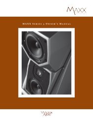
S e c t i o n 1 . 1 – I n t r o d u c t i o nSection 1.1 – IntroductionFrom all of us at <strong>Wilson</strong> <strong>Audio</strong> Specialties — thank you for purchasing the <strong>Alexandria</strong>®X-2 <strong>Series</strong> 2 loudspeaker. The information contained within the pages of this manualwill inform and instruct you as to how you may enhance and prolong the enjoymentof your <strong>Alexandria</strong> loudspeaker.The original <strong>Alexandria</strong> was the fruition of a blank-slate approach to creating a newflagship loudspeaker for the real world. It introduced radically new technologies, suchas Aspherical Propagation Delay, and capitalized on the synergistic application oftechnologies perfected in the decade since the revolutionary X-1 Grand SLAMM® platformwas introduced. Since that time, technologies introduced in the MAXX®, the WATT/Puppy®, and the Sophia® made it clear that it was time to revisit <strong>Alexandria</strong>.Among the technical innovations of the <strong>Alexandria</strong>:• All-new midrange driver developed specifically for the <strong>Series</strong> 2 <strong>Alexandria</strong>.• New improved tweeter. Back wave interference has been reduced to thelowest levels yet.• New crossovers potted in cases milled from “X” material. Microphonicsand mechanical interference are greatly reduced through this aggressivestrategy. Applying new technology in the realm of propagation delay jitter,the <strong>Alexandria</strong> <strong>Series</strong> 2 crossover is the most time coherent yet produced.• New back cover for easy access. The single cover has be replaced by two,which attach with <strong>Wilson</strong>’s stainless steel pin hardware. A tempered glasswindow allows the crossover and resistors to be viewed with the cover inplace.• New resistor connector plate with reduced resonance and greater heat dissipation.<strong>Wilson</strong> <strong>Audio</strong> Specialties11
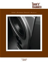
A l e x a n d r i a X - 2 S e r i e s 2 O w n e r ’ s M a n u a lAspherical Propagation DelayA musical waveform is a complex overlay of frequencies, amplitudes, and phaserelationships. With current technology, no single transducer can reproduce the full rangeof music at realistic sound pressure levels while maintaining consistent dispersion. Thesolution is the multiple driver array, with specific drivers dedicated to various portionsof the frequency range. Multiple drivers introduce their own set of problems, however,chief among them the challenge of preserving the precise time relationships of the musicalwaveform.The key to solving this problem lies in <strong>Wilson</strong>’s innovative and patented AdjustablePropagation Delay technology, which employs movable modules that allow theindividual adjustment of the drivers in the time domain. Using this technology, eachdriver’s waveform propagation“matches up” with itsneighbors’ in such a wayto create the sonic equivalentof a single point source.Certain other loudspeakermakers recognize the needto correctly align their drivers,but they do so for onlyone theoretical listening position.The fact is, misalignmentof the drivers by fractionsof an inch will audiblydegrade transient accuracy,soundstage height, depth,12Figure 1 – <strong>Alexandria</strong>’s Modules Move Aspherically toCorrect Propagation Delay<strong>Wilson</strong> <strong>Audio</strong> Specialties
S e c t i o n 1 . 1 – I n t r o d u c t i o nand width. Misalignment of the drivers will also introduce tonal anomalies that destroythe otherwise convincing “presence” of an instrument or a singer’s voice. <strong>Wilson</strong>’s solutionfor propagation delay correction has long set the standard for precise driver positioningin order to insure correct time alignment for a wide range of real room listeningFigure 2a - Typical loudspeakers exhibit less than optimumpropagation delay and dispersion characteristics. The soundquality is compromised for all listeners in all rooms.Figure 2b - Aspherical Propagation Delay optimizes driver/room interactionfor a variety of situations. This provides consistently optimizedresults in a wide range of rooms and listening positions.Figure 2 – <strong>Alexandria</strong>’s Modules Move Aspherically to Correct Propagation Delay<strong>Wilson</strong> <strong>Audio</strong> Specialties13
A l e x a n d r i a X - 2 S e r i e s 2 O w n e r ’ s M a n u a ldistances and ear heights.The signature curves in <strong>Alexandria</strong>’s cabinet are a further evolution of <strong>Wilson</strong>’sphilosophy that truly great forms follow a corresponding function. They are a visualmetaphor for the solution <strong>Wilson</strong> <strong>Audio</strong> pioneered to address issues of phase coherenceexacerbated by large speaker systems. Typical of the creative process, the solution itselfcame as a metaphor, or rather, an analogy to the field of optics and the design of wideanglelenses. The means of maintaining edge-to-edge sharpness at both close and farfocusing distances for a high quality wide-angle lens suggested a solution to the similarproblem of time domain accuracy for large speaker systems at both near and far listeningpositions.With <strong>Alexandria</strong>, <strong>Wilson</strong> <strong>Audio</strong> takes this concept a logical step further, addressingthe issue of optimal driver dispersion in the large cabinet system. Ideal driver dispersionfor both near and far listening positions requires the drivers be adjustable not only forwardand back, but also able to rotate on their polar axes.With <strong>Alexandria</strong> , for the first time ever, you and others you listen with, will hearyour favorite recordings and soundtracks with true time coherency, full frequency range,unfettered dynamics, and vanishingly low distortion. The improvement in realism wroughtby <strong>Alexandria</strong> X-2 <strong>Series</strong> 2 is delightfully revolutionary.14<strong>Wilson</strong> <strong>Audio</strong> Specialties
A l e x a n d r i a X - 2 S e r i e s 2 O w n e r ’ s M a n u a l16<strong>Wilson</strong> <strong>Audio</strong> Specialties
Section 2 – In Your Room
A l e x a n d r i a X - 2 S e r i e s 2 O w n e r ’ s M a n u a l18<strong>Wilson</strong> <strong>Audio</strong> Specialties
S e c t i o n 2 . 1 – R o o m A c o u s t i c sSection 2.1 – Room AcousticsYou are surely excited about setting up your <strong>Alexandria</strong> X-2 <strong>Series</strong> 2 loudspeakersand doing some listening, but before you begin, we would like to discuss some of theimportant room acoustical information that will help you set up your loudspeakers properly.Final Listening Room Setup (Voicing)For a speaker system its size, the <strong>Series</strong> 2 <strong>Alexandria</strong> X-2 is unmatched in its abilityto reproduce the musical event. It is truly state of the art. However, room acoustics andboundary interactions affect the sound of a loudspeaker to such a large degree that poorsetup can seriously degrade your enjoyment of even the finest loudspeaker.Therefore, we offer the following section, which will present some guidelines onroom acoustics and their interactions with loudspeakers. While we will also outline somedetailed suggestions on the setup of the <strong>Alexandria</strong>s, we strongly suggest that you haveyour local <strong>Wilson</strong> <strong>Audio</strong> dealer perform the final speaker “voicing” with you. <strong>Wilson</strong>dealers are specially trained in setting up <strong>Wilson</strong> loudspeakers and will ensure that yourealize the full value of your purchase.Zone of NeutralityThe “Zone of Neutrality” is an area in your room where the speakers will soundmost natural. This location is where the speakers interact the least with adjacent roomboundaries. It is important to have a clear working space while determining the Zone ofNeutrality.The following is a simple method to locate the Zone of Neutrality within your listeningenvironment:1. Stand against the wall BEHIND the location where you intend to position<strong>Wilson</strong> <strong>Audio</strong> Specialties19
S e c t i o n 2 . 2 – R o o m R e f l e c t i o n sin the room where your voice transitions from bass-heavy and diffuse toneutral. Mark this point with tape. Continue your progression until thereis an obvious interaction with the opposite wall in front of you and markthis point with tape. The four pieces of tape now form a rectangle that establishesthe Zone of Neutrality for the loudspeaker located on that side ofthe room. Using the four marks as your guide, tape an outline to define theboundaries of the rectangle.6. Repeat this process for each speaker location individually. These are yourZones of Neutrality, one for each channel.Theoretically, the Zone of Neutrality for any room runs like a path, parallel to thewalls all around the room. Adjacent to very large windows and open doors, the outeredge of the Zone of Neutrality moves closer to the wall and becomes wider. If you wereto extend the inner and outer boundaries of the Zone for the sidewalls and the front wall(behind the speakers), they would intersect. After you complete this procedure for theother loudspeaker, you will now have two rectangles, one on the floor on either side ofthe room.Note: The more reflective or “live” sounding the room is, the more difficult it will beto detect the changes in your voice; thus, you may have to repeat this process untilthe zones have been determined.Section 2.2 – Room ReflectionsNote: The following section contains general information on room acoustics and loudspeaker/roominteraction. The concepts outlined below are equally relevant whendealing with multi-channel audio or home theater. The careful application of theseconcepts, as you evaluate the acoustical characteristics of your own room configuration,will allow you to optimize the performance of your <strong>Alexandria</strong>s.Slap EchoProbably the most obnoxious form of reflection is called “slap echo.” With slapecho,primarily midrange and high frequency sounds reflect off of two parallel hard sur-<strong>Wilson</strong> <strong>Audio</strong> Specialties21
A l e x a n d r i a X - 2 S e r i e s 2 O w n e r ’ s M a n u a lfaces. The sound literally reverberates back and forth until it is finally dissipated overtime. You can test for slap echo in any room by clapping your hands sharply in the middleof the room and listening for the characteristic sound of the echo in the midrange. Slapecho destroys the sound quality of a stereo system in two ways:• It adds harshness to the upper midrange and treble by storing time-domainsmearing energy.• It destroys the delicate phase relationships, which help to establish an accuratesoundstage.Slap echo (see Figure 3) is a common acoustical problem in the typical domestic listeningroom because most of these rooms have walls with a hard, reflective nature, onlyFigure 3 – Common Room Reflection Problems22<strong>Wilson</strong> <strong>Audio</strong> Specialties
A l e x a n d r i a X - 2 S e r i e s 2 O w n e r ’ s M a n u a ldirectly beside the speakers. It is our experience that all of these room treatment devicesshould be used judiciously.Standing WavesAnother type of reflection phenomenon is “standing waves.” Standing waves causethe unnatural boosting or accentuation of certain frequencies, typically in the bass, tobe found at certain discreet locations in the room. These locations differ according toroom dimension and size. A room generating severe standing waves creates difficulty insetup. In these rooms, the speaker will sound radically different as it is moved around.The effects of standing waves on a loudspeaker’s performance are primarily in the areaslisted.• Tonal balance• Resolution of low-level detail• SoundstagingStanding waves are more difficult to correct than slap echo because they tend tooccur at a lower frequency. Absorbent materials, such as Illbruck Sonex®, are ineffectiveat controlling reflections in the bass region. Moving speakers about slightly in theroom is, for most people, their only control over standing waves. Sometimes a change ofplacement of as little as two or three inches can dramatically alter the tonal balance ofa small system.Fortunately, minor low frequency standing waves are well controlled by positioningASC Tube Traps in the corners of the room. Very serious low frequency accentuationusually requires a custom-designed bass trap system.Low frequency standing waves can be particularly troublesome in rooms constructedof concrete or brick. These materials trap the bass in the room unless it is allowed to24<strong>Wilson</strong> <strong>Audio</strong> Specialties
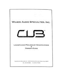
A l e x a n d r i a X - 2 S e r i e s 2 O w n e r ’ s M a n u a lsitting. Additionally, these longrooms are often quite lean in thebass near the center of the room.Rectangular rooms are still preferredto square rooms because,by having two sets of dissimilarlength walls, standing wavesare not as strongly reinforcedand will dissipate more quicklythan in a square room. In theserooms, the preferred speaker positionfor spatial placement andmidrange resolution would be onthe longer walls. Bass responsewould be reinforced by speakerplacement on the short walls.In many cases, L-shapedrooms (See Figure 4) offer thebest environment for speakersetup. Ideally, speakers shouldbe set up along the primary (longest)leg of the room. They shouldfire from the end of the leg (shortwall) toward the L, or they shouldbe along the longest wall. In thisway, both speakers are firing thesame distance to the back wall.Figure 4 – Possible Loudspeaker Placement withinVarious Room Shapes28<strong>Wilson</strong> <strong>Audio</strong> Specialties
S e c t i o n 2 . 4 – Y o u r R o o mThe asymmetry of the walls in L-shaped rooms resists the buildup of standing waves (seeFigure 4).<strong>Alexandria</strong> X-2 <strong>Series</strong> 2 in a Dedicated Home TheaterHome theaters can be organized many different ways. Some use rows of couches.Others use rows of multiple chairs.In addition to watching movies, most users want to listen to two-channel music atthe highest quality possible. It is desirable, therefore, to choose a single optimum seatingposition in a home theater and build the rest of the seating positions around this position.If your optimum position is located on a couch, you should center the loudspeakerson the middle position of the couch.If the seating area consists of multiple rows of chairs, the second row should beoptimized for the best sound quality. Odd numbers of chairs arranged in rows work bestas this will allow a single chair to be positioned in the center. This approach will alsoprovide the best overall sound for the greatest number of seats.Speaker Placement Versus Listening PositionThe location of your listening position is as important as the careful setup of your<strong>Alexandria</strong> speakers. The listening position should ideally be no more than 1.1 to 1.25times the distance between the tweeters on each speaker. Therefore, in a long, rectangularroom of 12’ x 18’, if the speaker tweeters are going to be 9’ apart, you should besitting 9’11’’ to 11’3’’ from the speaker. This would be more than halfway down the longaxis of the room.Many people place the speakers on one end and sit at the other end of the room.This approach will not yield the finest sound. Carefully consider your listening position.Our experience has shown that any listening position that places your head closer than14” from a room boundary will diminish the sonic results of your listening.<strong>Wilson</strong> <strong>Audio</strong> Specialties29
A l e x a n d r i a X - 2 S e r i e s 2 O w n e r ’ s M a n u a lDecide where you want your favorite listening position to be. Please remember thatyour <strong>Alexandria</strong> X-2 <strong>Series</strong> 2 will fill almost any room with the most beautiful soundavailable. Because the propagation delay is adjustable on the <strong>Alexandria</strong>s, if you takecare in placing your new speakers, you will optimize <strong>Alexandria</strong>’s performance in yourroom.Speaker OrientationSpeaker placement and orientation are two of the most important considerationsin obtaining superior sound. The first thing you need to do is eliminate the sidewalls asa sonic influence in your system. Speakers placed too close to the sidewalls will sufferfrom a strong primary reflection. This can cause out-of-phase cancellations, or comb filtering,which will cancel some frequencies and change the tonal balance of the music.The <strong>Wilson</strong> <strong>Audio</strong> Setup Procedure (Section 2.1) is the best method with which to positionyour loudspeakers. Start with the speakers about 18” from each wall and, if you needto move them relative to the side wall, move them away from the wall, not closer.A very important aspect of speaker placement is how far from the back wall to placethe speakers. The closer a loudspeaker is to the back wall, the more pronounced the lowbass energy and centering of the image will be. However, this comes at a definite reductionin stage size and bloom as well as a deterioration of upper bass quality. You mustfind the proper balance of these two factors, but remember, if you are partial to bassresponse or air and bloom, do not overcompensate your adjustments to maximize theseeffects. Overcompensated systems are sometimes pleasing in the short-term, but longtermsatisfaction is always achieved through proper balance.The <strong>Series</strong> 2 <strong>Alexandria</strong> is designed for maximum phase coherence and pulse replicationaccuracy when each speaker is aimed directly at the listener or microphone.Thus, your <strong>Alexandria</strong> should be “toed in.” In other words, the listener, when seated inthe listening position looking forward with his/her head in a rested position, should just30<strong>Wilson</strong> <strong>Audio</strong> Specialties
S e c t i o n 2 . 4 – Y o u r R o o mbarely see the surface of the inner side of each <strong>Alexandria</strong>. Toeing in the speakers providesmeaningful improvements in resolution of low-level detail in the midrange as wellas appreciable improvements in soundstaging performance.SummaryIn summary, for optimal tonal balance accuracy, resolution of low level detail, andsoundstaging performance, the <strong>Alexandria</strong> X-2 <strong>Series</strong> 2 should be positioned as outlinedin this section. Ideally, the speakers should not be positioned too far from the listener ifmaximum resolution of low-level detail is required. If possible, the speakers should bepositioned out into the room, slightly asymmetrically vis-a-vis the side and rear walls.The speakers should be “toed in” toward the listener, preferably so that the listener, athis seated position, can barely see the surface of the inner side of the <strong>Alexandria</strong> as he/she faces the speaker. It is recommended that a distance of two to three feet, and possiblymore, be maintained between the <strong>Alexandria</strong> and the rear walls and that a distance of atleast two feet be maintained between the front panel of the <strong>Alexandria</strong> and reflective sidewalls. Depending on the room, judicious use of sound absorbent materials will reducethe space requirement.By following the guidelines in this manual, your new <strong>Alexandria</strong> X-2 <strong>Series</strong> 2 loudspeakerscan provide you with a lifetime of pure music reproduction.<strong>Wilson</strong> <strong>Audio</strong> Specialties31
<strong>Wilson</strong> <strong>Audio</strong> Specialties
Section 3 – Uncrating the <strong>Alexandria</strong>
A l e x a n d r i a X - 2 S e r i e s 2 O w n e r ’ s M a n u a l34<strong>Wilson</strong> <strong>Audio</strong> Specialties
S e c t i o n 3 . 1 – U n c r a t i n g t h e A l e x a n d r i aNote: You will have many modules to unpack that will need to be separated into rightand left channels. Clear out two spaces, one for your left and one for your right channelmodules. Place the ODD numbered modules in the LEFT channel section and theEVEN in the RIGHT channel section. Prior to assembly, stage the modules away fromthe area where the speakers are to be assembled. This will avoid clutter in the workarea that can result in damage to your loudspeakers.Section 3.1 – Uncrating the <strong>Alexandria</strong>Initial CheckThe <strong>Alexandria</strong> is shipped in sevenwooden crates. Upon receiving thesecrates, please check their condition. Ifany of the crates are damaged, pleasereport it to the shipping company immediatelyfor insurance verification.Tools Required• Metal shears• Variable speed, reversibleelectric drill• Phillips head drive bitUncrating the Woofer ModulesA minimum of two strong adults isrequired to set up the system. Locatethe two largest crates labeled “WooferModule.” These contain the woofer en-Figure 5 - Woofer Module<strong>Wilson</strong> <strong>Audio</strong> Specialties35
A l e x a n d r i a X - 2 S e r i e s 2 O w n e r ’ s M a n u a lclosures and are the first components of the system to unpack (see Figure 5).Note: These two woofer enclosures are very heavy and when moving or lifting, careshould be taken in order to prevent injury.Unpacking the Woofer1. Open the top of each crate and determine the side where the casters areconnected to the bottom of the woofer module.2. Remove the packing material from between the casters and set the crate upso that the casters on the woofer are toward the floor.3. While one person holds the crate, the other person should roll the wooferenclosure out of the crate. Be very careful not to scratch the module duringthis process.4. Finally, move the woofer cabinets over to the “Zone of Neutrality” as determinedby the <strong>Wilson</strong> <strong>Audio</strong> Setup Procedure. If you have not yet performedthis room analysis, please refer to Section 2.1 of this manual. Reminder:Place the odd serialnumbered woofer onthe LEFT and the evennumbered woofer onthe RIGHT.5. Remove the emptywoofer crates from theroom.Uncrating the Aspherical WingsLocate the two crates labeled“Wing Assembly” (see Figure 6).These contain the wings that supportthe upper modules.Figure 6 - Wing Array36<strong>Wilson</strong> <strong>Audio</strong> Specialties
1. Cut the bands on the crate.S e c t i o n 3 . 1 – U n c r a t i n g t h e A l e x a n d r i a2. Remove all the screws from thetop and sides of the crate.3. Pull the top of the crate off,and pull the sides of the crateapart.4. Because the wing array is extremelyheavy, use two strongpeople to carefully lift thewing array out of the crate.Upper Midrange Module (UMRM)5. Locate the serial plate on theunderside of the lower horizontalsupport. Place thewings on the floor near thewoofer modules, matched tothe woofer module with thesame serial number.High Frequency Module (HFM)6. Remove the empty shippingcrates from the room.Uncrating the Upper Array Modules1. Locate the two crates labeled“Upper Modules.” Removethe three upper modules,from each crate (see Figure7). It is very important to ensurethat each of the modulesare matched to one anotherby serial number. The serialtags are located on the un-Lower Midrange Module (LMRM)Figure 7 - Uncrate Upper Modules<strong>Wilson</strong> <strong>Audio</strong> Specialties37
A l e x a n d r i a X - 2 S e r i e s 2 O w n e r ’ s M a n u a lFigure 8 - Propagation Delay CoverFigure 9 - Resistor Plate Coverderside of each module. Be very careful in unpacking the remaining modulesto avoid chipping the finish.2. Stage these items away from traffic flow.3. Remove the empty crates from the room.Uncrating the Crossover Cover1. Locate the crate labeled “Crossover Covers” (see Figures 8 & 9). This cratecontains the propagation delay cover and the resistor plate cover. It alsocontains tool kits, a jack, and an owner’s manual. Remove the covers fromthe crate. Take care to observe the serial number and place the covers withthe corresponding channel’s modules.2. Remove the empty crates from the room.38<strong>Wilson</strong> <strong>Audio</strong> Specialties
S e c t i o n 3 . 1 – U n c r a t i n g t h e A l e x a n d r i aCrate Contents ChecklistNow that you have everything unpacked, you can inventory your items.1 - Owners manual2 - Woofer modules (left & right channel)2 - Lower midrange modules (left & right channel)2 - High frequency modules (left & right channel)2 - Upper midrange modules (left & right channel)2 - Wing Arrays (left & right channel)2 - Propagation Delay Alignment Plates (left & right channels)8 - 3/8”-16 x 1.5 set screws8 - Spikes, with nuts8 - Woofer Mechanical Diode1 - Caster wrench1 - Jack1 - 9/16” Combo wrench1 - 3/16” Long-arm Allen wrench1 - 5/32” Allen wrench1 - 1/2” Binding post wrench1 - 9/64” Allen wrench4 - Expansion spike sub-assemblies18 - “A” spikes6 - “B” spikes6 - “C” spikes6 - “D” spikes6 - “E” spikes12 - #1 Tether bolts12 - #2 Tether bolts<strong>Wilson</strong> <strong>Audio</strong> Specialties39
A l e x a n d r i a X - 2 S e r i e s 2 O w n e r ’ s M a n u a l12 - Tether bolt threaded covers2 - Polishing cloths8 - Large Brass spike pads1 - Bottoming tap - 3/8”-161 - Tap Handle12 - ¼” x .468” Washer12 - ¼” - 20 x 1 ¼” Socket head screws16 - 10 - 32 x 1” Socket head screws16 - 10 x .438” WasherComplete set of resistors:4 sets of 2 (soldered in series) - .75 ohm tweeter and/ormidrange level resistors2 - 34.6 ohm midrange phase resistor2 - 27.3 ohm woofer barrel resistor, (for solid state amplifiers)4 - 23.4 ohm woofer barrel resistor, (for tube amplifiers)Note: After set up of the system, keep the shipping crates in case of future shippingneeds.40<strong>Wilson</strong> <strong>Audio</strong> Specialties
S e c t i o n 3 . 1 – U n c r a t i n g t h e A l e x a n d r i a<strong>Wilson</strong> <strong>Audio</strong> Specialties41
A l e x a n d r i a X - 2 S e r i e s 2 O w n e r ’ s M a n u a l42<strong>Wilson</strong> <strong>Audio</strong> Specialties
Section 4 – Assembling Your <strong>Alexandria</strong>s
S e c t i o n 4 . 1 – I n i t i a l A s s e m b l yFigure 12 – When re-installing the Propgation Delay Plate, insert the tether bolts in the rearslots on either side of the numbered plate.• Select the proper tether bolt by referring to the lower midrange moduletether bolt length table found in Section 8. See Section 4.2 below for theprocess to determine the proper tether bolt.• Locate the two appropriate length lower midrange module tether bolts.• Insert tether bolts through the bottom of the plate (see Figure 12) so thatthe threaded portion of the bolt protrudes through the top of the plate.• Attach the plate to the top of the woofer module (see Figure 12). Ensurethat the tether bolts stay in place.• Secure the plate with the eight 10 - 32 x 1” bolts, placing the metal wash-<strong>Wilson</strong> <strong>Audio</strong> Specialties47
A l e x a n d r i a X - 2 S e r i e s 2 O w n e r ’ s M a n u a l3. Make sure that you are in your intended listening position.4. While sitting, have someone measure your ear height from the floor directlybelow your ear. You should be relaxed in your chair, as you wouldbe when listening to music (see Figure 13).5. Now measure the distance (on the floor) from the point on the floor belowyour ear to the base of the loudspeaker, as shown in Figure 13.6. Refer to the Propagation Delay Tables (see Section 8) and locate the correspondingear height for each module. There are three charts per module;the first is a table determining the rear spike length, the second is a nomograph(accompanied by a table) determining each module’s rear spikeindent location, and the third table specifies the appropriate Tether Boltlength.7. Make a mark on the “Rear Spike Length” tables indicating the proper rearspike for each module.Note: The shortestspikes (labeled A)are always used atthe front of all uppermodules.8. Make a mark on the“Rear Spike DetentLocation” table indicatingthe properrear spike locationfor each module.Set this informationaside as you will referto it in the nextsection.Figure 14 - Alignment plate with spike detents50<strong>Wilson</strong> <strong>Audio</strong> Specialties
A l e x a n d r i a X - 2 S e r i e s 2 O w n e r ’ s M a n u a land heads.The front-to-back location of each module, along with the use of the proper lengthof rear spike of the upper modules, achieves the correct propagation delay and axial responsevis a vis the listener.Install the front pair of short (A length) spikes into the bottom of each module (seeFigure 15).Install the Lower Midrange Module (LMRM)The lower midrange module (LMRM) is installed first. Install the module as follows:• With the front spikes pointing down, carefully lower the LMRM betweenthe alignment wings and set it on top of the woofer enclosure (see Figure16). Ensure that the tether bolts are protruding through the slots providedin the module handle. There are alignment tracks that accommodate thespikes. Refer to the Propagation Delay Table to determine the numberedindent in which to rest the rear spike.• It is now safe to install the rear spike by lifting the module by its rear handleand carefully screwing in the spike.• The rear spike track is indexed numerically. Refer to your marks on thePropagation Delay Table in Section 8.0 to determine the numbered detentin which to rest the rear spike.Install the High Frequency Module (HFM) as follows:• With the front pair of short spikes pointing down, carefully lower the HFMbetween the alignment wings and set the front two spikes on top of theLMRM enclosure. Align the spikes into the alignment tracks. Install the rearspike by lifting the rear of the HFM and carefully screwing it in.• Refer to the Propagation Delay Table in Section 8 to determine the properlocation of the rear spike, noting that the position will be different from theLMRM.52<strong>Wilson</strong> <strong>Audio</strong> Specialties
S e c t i o n 4 . 4 – C o n n e c t i n g t h e U p p e r M o d u l e s ’ S i g n a l C a b l eInstall the Upper Midrange Module(UMRM) as follows:• With the front pair ofshort spikes pointingdown, carefully lowerthe UMRM between thealignment wings. Set thefront two spikes on topof the HFM enclosure,into the tracks. Installthe rear spike by liftingthe rear of the UMRMand carefully screwing itin.• Refer to the PropagationDelay Table in Section 8to determine the properlocation of the rear spike,noting that the positionwill be different from theother two modules.Section 4.4 – Connecting theUpper Modules’ Signal CableThe <strong>Alexandria</strong> uses binding poststhat were designed in-house and aremanufactured exclusively for <strong>Wilson</strong><strong>Audio</strong>. The design goal was to create aconnector with superior overall soundquality, consistency, and longevity.Figure 16 - Install the upper modules into the wingarray.<strong>Wilson</strong> <strong>Audio</strong> Specialties53
A l e x a n d r i a X - 2 S e r i e s 2 O w n e r ’ s M a n u a lA note about these connectors: You risk breaking the binding post if they are overtightened.Use the supplied binding post wrench and tighten until just snug.The upper range signal cables are labeled so that they can be easily attached totheir appropriate module. This is accomplished as follows:• Locate the cable marked “Lower Mid.” Dress this cable through the handleopening and connect this cable to the lower midrange module (LMRM)loudspeaker binding post (see Figure 17).• Locate the cable marked “Front Tweeter.” Dress this cable through thehandle opening and connect it to the high frequency module (HFM) loud-Figure 17 - Cable Dressing.54<strong>Wilson</strong> <strong>Audio</strong> Specialties
S e c t i o n 4 . 4 – C o n n e c t i n g t h e U p p e r M o d u l e s ’ S i g n a l C a b l espeaker binding post (see Figure 17).• Locate the cable marked “Upper Midrange.” Locate the binding post onthe rear of the upper midrange module (UMRM) labeled “Mid Frequency.”Carefully thread the speaker cable up through the hole located in the wingsupport and through a corresponding hole located on the module supportblade just below the speaker terminal (see Figure 18).• Locate the cable marked “Rear Tweeter.” Locate the binding post on therear of the upper midrange module labeled “Rear Tweeter.” Carefullythread the speaker cable up through the hole located in the wing supportFigure 18 - Connect cables to the upper modules.<strong>Wilson</strong> <strong>Audio</strong> Specialties55
A l e x a n d r i a X - 2 S e r i e s 2 O w n e r ’ s M a n u a lFigure 19 - Install the tether bolts. Cutaway of X-2 showing bolt assembly.and through a corresponding hole located on the module support bladejust below the speaker terminal (see Figure 18).Section 4.5 – Locking Down The Upper ModulesMaterials RequiredRefer to “Identification of Alignment Spikes and Tether Bolts” in Section 4.1 under“Geometric Time Domain Alignment” to ensure that you have the proper length tetherbolts for each loudspeaker’s upper two modules.56<strong>Wilson</strong> <strong>Audio</strong> Specialties
S e c t i o n 4 . 6 – S p i k e I n s t a l l a t i o n2 - Tether bolt cap nuts for each loudspeaker’s lower midrange module(LMRM).2 - Tether bolts for each loudspeaker’s high frequency modules (HFM).2 - Tether bolt cap nuts for each loudspeaker’s high frequency modules (HFM).2 - Tether bolts for each loudspeaker’s upper midrange module (UMRM).2 - Tether bolt cap nuts for each loudspeaker’s upper midrange module(UMRM).Installing The Tether Bolts• The tether bolts for the lower midrange module have already been installedbeneath the alignment plate (see Section 4.1). Place the tether cap nutsand rubber washers on the bolts, alternatively tightening them in small incrementsso that LMRM is tensioned symmetrically and snugly against thepropagation delay spike (see Figure 19).Note: Do not use any tools to tighten the tether cap nuts. Hand tighten only. Overtensioningof the bolts can damage the module.• Insert the high frequency module (HFM) tether bolt through the bottom ofthe center wing plate, up through the the corresponding tether bolt slot onthe module handle. While holding the bolt in place, thread the tether capnut onto the bolt and loosely tighten it. Install the second HFM tether boltusing the same process. After the two bolts are secured in place, check toensure that the alignment spike is still placed properly in its numbered detent.Symetrically hand tigten the tether cap nuts.• Using the same process, insert and symetrically tighten the tether cap nutsfor the upper midrange module.Section 4.6 – Spike Installation<strong>Wilson</strong> <strong>Audio</strong> Specialties57
A l e x a n d r i a X - 2 S e r i e s 2 O w n e r ’ s M a n u a lSpike Assembly• Remove the mechanicaldiodes and moveSetscrewthe nut to about twoMechanical Diodethreads from thepoint. This will allowAllen Key Endforgreater movementwhen levelingthe loudspeaker system.3/8” NutSpike• Screw the spikes intothe diode until theFigure 20 - <strong>Alexandria</strong> Spike and Diode Assemblynut is against thediode. Be careful that the nut does not turn while inserting and threadingspikes into the diode.Note: Do not tighten these assembled spikes. You will need to unscrew themwhen you level the Alexendrias.• Place the set screw into the other end of the diode with the Allen head towardthe spike. This will ensure that if for any reason you have to removeyour <strong>Alexandria</strong> spikes, you will be able to withdraw the set screw safelyusing the supplied Allen wrench. Screw the set screw into the diode untilit meets the spike (see Figure 20).• Place the assemblies out of the traffic pattern until they are needed duringthe installation.58<strong>Wilson</strong> <strong>Audio</strong> Specialties
Section 4.7 – Using the Lift to Install SpikesS e c t i o n 4 . 7 – U s i n g t h e L i f t t o I n s t a l l S p i k e sMaterials RequiredNote: This is a two person job. Do not attempt this by yourself. The <strong>Alexandria</strong>s weighover 700 LBS and may seriously injure someone if tipped over.Figure 21 - Installing the spikes using the <strong>Wilson</strong> <strong>Audio</strong> Jack<strong>Wilson</strong> <strong>Audio</strong> Specialties59
A l e x a n d r i a X - 2 S e r i e s 2 O w n e r ’ s M a n u a l• 8 sets of assembled spikes• The <strong>Wilson</strong> <strong>Audio</strong> Jack• The jack socket wrench• Swivel caster wrenchInstallation Procedure• Lock the rear casters to prevent the <strong>Alexandria</strong> from moving.• Slide the <strong>Wilson</strong> <strong>Audio</strong> Jack under the front of the <strong>Alexandria</strong>, centered betweenthe casters, so that the jack’s lift bolt is exposed. Place the lift plateso it is positioned about an inch behind the front facade of the <strong>Alexandria</strong>woofer enclosure (see Figure 21).Note: An assistant should stand to the rear of the <strong>Alexandria</strong> to steady it.• Attach the wrench to the lift bolt and begin to slowly raise the front of the<strong>Alexandria</strong> by turning the bolt clockwise (see Figure 21).• After the front of the <strong>Alexandria</strong> is high enough (you will need approximatelyone and half inches of clearance beneath the caster), use the swivelcaster wrench to loosen the casters. Remove the casters.• Insert and screw-in the finished spike assembly. Hand tighten only!Note: Be very careful NOT TO CROSS THREAD the spikes. The base of the <strong>Alexandria</strong>sis made of “X” material and is prone to cross threading.Note: The spike will go into a different hole than the caster.• With one person stabilizing the <strong>Alexandria</strong>, lower the <strong>Alexandria</strong> by turningthe jack counterclockwise. Note that the <strong>Alexandria</strong> will now sit lowerin the front as the spike assembly is shorter than the caster. Use caution.60<strong>Wilson</strong> <strong>Audio</strong> Specialties
S e c t i o n 4 . 7 – U s i n g t h e L i f t t o I n s t a l l S p i k e sNote: It is very important, at this point, that an able assistant stabilize the front ofthe <strong>Alexandria</strong> until the rear spikes are attached and the unit is lowered.• Repeat the previous process of the caster removal/spike insertion on theopposite side of the enclosure. Then continue the process on the otherchannel (see Figure 21).Figure 22 - Install the extensions spikes.<strong>Wilson</strong> <strong>Audio</strong> Specialties61
A l e x a n d r i a X - 2 S e r i e s 2 O w n e r ’ s M a n u a lLeveling the <strong>Alexandria</strong>• It is not necessary to use the jackto level the <strong>Alexandria</strong>.• Place a level on the left to rightoriented axis. If it is level, move tothe next step.• If the bubble shows that the speakeris leaning toward the center ofthe room, you will have to lengthenone of the inside spikes down towardthe floor. If the bubble isleaning toward the outside of theroom, you will have to lengthenone of the outside spikes down towardthe floor.• You may rotate the spike tipsin place by using a vice-grip ortoothed pliers.• To find out which spike to lower,Figuregrasp the <strong>Alexandria</strong> channel and23 - Install the back Covers.rock it back and forth. This willidentify the spike that is out of level from the other three.• Place a level on the front to back oriented axis. If it is level, then your<strong>Alexandria</strong>s are level. If the bubble shows that the speaker is leaning towardthe front of the room, you will have to lengthen the front spikes downtoward the floor. If the bubble shows that the speaker is leaning toward theback of the room (behind the loudspeakers), you will have to lengthen therear spikes down toward the floor.62<strong>Wilson</strong> <strong>Audio</strong> Specialties
S e c t i o n 4 . 8 – E x t e n s i o n S p i k e sSection 4.8 – Extension SpikesPlace one end of the expansion spike sub-assembliesinto the last hole of the spiketrack. Expand the sub-assembly until the upper end comes into contact with the dimplein the middle of the brass spike pad found on the underside of the wing braces. Use boxend wrenches (included) to snug the expansion spikes securely (see Figure 22).Section 4.9 – Installing the Back CoversAttach the cover over theresistor plate. The cover attachesusing the same stainlesssteel pin system as the grills(see Figure 23).Note: The rear resistor coverfeatures a glass insert. Takecare when installing or storingthe cover to avoid breakingthe glass.Attach the top cover overthe propagation delay hardware.Section 4.10 – ResistorsBy removing the backcover of your <strong>Alexandria</strong>s, youmay gain access to the resistorplate (see Figure 23). These resistorsserve several functions.Note: Only <strong>Wilson</strong> <strong>Audio</strong>replacement resistors shouldbe used in your <strong>Alexandria</strong>s.Figure 24 - Resistor Chart<strong>Wilson</strong> <strong>Audio</strong> Specialties63
A l e x a n d r i a X - 2 S e r i e s 2 O w n e r ’ s M a n u a lChanging the value or brand of resistor will have a deleterious affect on the sonic performanceof your loudspeakers and may void your <strong>Wilson</strong> <strong>Audio</strong> Warranty.Midrange and Front Tweeter ResistorsThe Midrange Level and Front Tweeter Level resistors provide precise level matchingfor the midrange and tweeter drivers correspondingly. The resistors also act as ultra highquality fuses which open before a driver can be damaged by excess power. See Section6.0 for details in replacing these resistors in the event one of these two resistors is damaged.Additionally, these two resistors can be usedto tailor the output of the corresponding driverto overcome tonal balance issues that result fromroom acoustics. Refer to Figures 23 through 25 forinformation important to this adjustment.Midrange Phase ResistorsThe Midrange Phase resistor is a propagationdelay tuning device and should never be changedor altered by the user.Woofer Damping ResistorThe Woofer Damping resistor affects the waythe <strong>Alexandria</strong>’s woofers couple to the amplifier.Generally, for direct coupled, solid state amplifiers,the Light Damping resistor (27.3 ohms) shouldbe used. With tube amplifiers, the Medium Dampingresistor (23.4 ohms) should be used (see Figures23 through 25).Figure 25 - Resistor Plate64<strong>Wilson</strong> <strong>Audio</strong> Specialties
S e c t i o n 4 . 1 1 – B r e a k - i n P e r i o dSection 4.11 – Break-in PeriodAll audio equipment will sound its best after its components have been broken infor some period of use. <strong>Wilson</strong> <strong>Audio</strong> breaks in all woofers and mid-range drivers for a12 hour period. All drivers are then tested, calibrated, and matched for their acousticalproperties. In your listening room, expect 25 to 50 percent of break-in to be complete aftertwo hours of playing music fairly loudly. Ninety percent of break-in is complete after24 hours of playing. Playing a “disc repeat” overnight can accomplish this task quickly.<strong>Wilson</strong> <strong>Audio</strong> recommends chamber music for this task.<strong>Wilson</strong> <strong>Audio</strong> Specialties65
A l e x a n d r i a X - 2 S e r i e s 2 O w n e r ’ s M a n u a l66<strong>Wilson</strong> <strong>Audio</strong> Specialties
Section 5 – Care of <strong>Alexandria</strong> X-2
A l e x a n d r i a X - 2 S e r i e s 2 O w n e r ’ s M a n u a l68<strong>Wilson</strong> <strong>Audio</strong> Specialties
S e c t i o n 5 . 1 – C a r e o f t h e P a i n t e d F i n i s hSection 5.1 – Care of the Painted FinishYour <strong>Alexandria</strong> <strong>Series</strong> 2 loudspeakersare hand painted with <strong>Wilson</strong>Glosspaint and hand polished to a high luster.While the finish seems quite dry to thetouch, final curing and complete hardeningtakes place over a period of severalweeks. To protect the finish of the <strong>Alexandria</strong>during final manufacture, shipment,and setup in your listening room, we haveapplied a removable layer of protectivefilm over the finish. We recommend thatthis film be left in place until the speakersare in their final location in your listeningroom. Once you have determined their finalposition, remove the film by peelingit off.Do not leave this film on indefinitely as it may leave impressions on the paint.It is important that the delicate paint finish of the <strong>Alexandria</strong> be dusted carefullywith the dust cloth, which has been provided. We recommend that the following procedurebe observed when dusting the speakers:• Blow off all loose dust.• Using the special dust cloth as a brush, gently whisk off any remainingloose dust.• Shake out the dust cloth.<strong>Wilson</strong> <strong>Audio</strong> Specialties69
A l e x a n d r i a X - 2 S e r i e s 2 O w n e r ’ s M a n u a l• Dust the finish, using linear motions in one direction parallel to the floor.Avoid using circular or vertical motions.Because the paint requires a period of several weeks to fully cure, we recommendthat no cleaning fluids, such as glass cleaners, be used during this initial period of time.When the paint is fully cured, heavy fingerprints and other minor smudges may be removedwith a glass cleaner. Always use the dust cloth. Stronger solvents are not recommendedunder any circumstances. Consult your dealer for further information if required.To maintain the high luster of the finish, periodic polishing may be desired over theyears. We recommend a nonabrasive carnauba-based wax and a soft cloth.Care of the GrillesPeriodically, you will want to clean the <strong>Alexandria</strong>’s. This is best done by usingthe round brush attachment on a vacuumcleaner hose. Gently vacuum the frontsurface of the grille. Be careful not to applytoo much pressure. Do not use a hardplastic attachment against the grille. Thegrille cloth is stretched tightly over thegrille frame. Too much pressure or use ofa hard plastic attachment could cause thegrille material to tear, especially in thecorners.Often <strong>Wilson</strong> speaker owners desireto change the look of their listening roomby changing the color of their speakergrilles. In addition to basic black, <strong>Wilson</strong><strong>Audio</strong> offers a variety of grille colors to70<strong>Wilson</strong> <strong>Audio</strong> Specialties
S e c t i o n 5 . 2 – E n c l o s u r e C o n s t r u c t i o nmatch most <strong>Wilson</strong>Gloss finishes. Contact your local dealer for grille cloth samples or toorder replacement grilles for your X-2 <strong>Alexandria</strong>.Section 5.2 – Enclosure ConstructionAt the core of each <strong>Wilson</strong> <strong>Audio</strong> loudspeaker design is the knowledge that toachieve the best performance, you must start with the best materials. Here are a fewof the elements that contribute to the <strong>Alexandria</strong> <strong>Series</strong> 2 enclosure’s supreme performance.MaterialThe <strong>Alexandria</strong>’s low frequency enclosure is constructed from a high-density, phenolicresin based composite. This composite meets and exceeds the highest of ANSI teststandards for its use, while offering very tight tolerances, high hardness, uniform density,and dimensional stability. In the construction of the <strong>Alexandria</strong> <strong>Series</strong> 2, <strong>Wilson</strong> <strong>Audio</strong>uses two types of composites dubbed “X” material and “M” material. These strategiccombinations of X and M materials are used in the two midrange modules, resulting inthe most inert enclosures yet produced. X material is used exclusively in the woofer andtweeter modules.The high hardness of this composite not only offers excellent acoustical properties,but it also provides an ideal surface for painting.Adhesive<strong>Wilson</strong> <strong>Audio</strong> has conducted exhaustive research into the best adhesives to permanentlybond our speaker enclosures. This is an often overlooked element crucial to theproper performance of a loudspeaker. Correct modulus of elasticity, coefficient of thermalexpansion, and natural frequency response are just a few of the important elementsof adhesives.A highly cross-linked, thermoset adhesive is used for the construction of the enclo-<strong>Wilson</strong> <strong>Audio</strong> Specialties71
A l e x a n d r i a X - 2 S e r i e s 2 O w n e r ’ s M a n u a lsure. It was also chosen for its excellent bond strength, solvent resistance, hardness, andoptimum vibrational characteristics.ConclusionThe combination of the best in composite materials and adhesive technology, providedto us by the leaders in their industries, allows us to design an enclosure withunmatched performance. The X-2 <strong>Alexandria</strong>’s upper and lower cabinet modules havebeen designed to eliminate vibration and cabinet signature while maintaining an internalacoustical integrity. <strong>Wilson</strong>’s exhaustive research into the effects of materials, enclosureconstruction strategies, and adhesives has yielded a product that maintains the stricteststructural tolerances, durability, and reliability. The <strong>Alexandria</strong>’s performance is repeatableand is unaffected by different climatic conditions throughout the world. The <strong>Alexandria</strong>X-2 <strong>Series</strong> 2 redefines the boundaries of what is possible in enclosure design.72<strong>Wilson</strong> <strong>Audio</strong> Specialties
S e c t i o n 5 . 2 – E n c l o s u r e C o n s t r u c t i o n<strong>Wilson</strong> <strong>Audio</strong> Specialties73
A l e x a n d r i a X - 2 S e r i e s 2 O w n e r ’ s M a n u a l74<strong>Wilson</strong> <strong>Audio</strong> Specialties
Section 6 – Troubleshooting
A l e x a n d r i a X - 2 S e r i e s 2 O w n e r ’ s M a n u a l76<strong>Wilson</strong> <strong>Audio</strong> Specialties
S e c t i o n 6 – T r o u b l e s h o o t i n gOne channel is not operating:Check the interconnects from source.Check the connections on the speakercables, both at the amplifier andspeaker ends. Watch especially forconnectors touching each other.Check the Upper Range Signal Cables.You may have forgotten to connectthem, or they may have shortedor come loose during setup.Imaging is off-center:Check your connections. A connectionto one of the modules may havecome loose. When a tweeter or midrangedriver is not working, or isout of phase, the <strong>Alexandria</strong> will not“image” properly. Double check yourconnections for red-to-red and blackto-black.Play music at a low level and listento each driver in each channel. Youmay have a driver that is not operatingcorrectly. If you find a driverthat is silent, please go to the “DriverOut” section of this troubleshootingguide.A chronic lack of bass energy:Driver out or not playing after connectionshave been verified:Check the input cable connections onyour woofer enclosure. If one channelis out of phase (connections reversed),bass will be cancelled. Note:Turn off your amplifier and unplug itfrom the wall.If you have found a driver with nooutput, move to the rear of this particularloudspeaker.Remove the back cover exposing the<strong>Wilson</strong> <strong>Audio</strong> Specialties77
A l e x a n d r i a X - 2 S e r i e s 2 O w n e r ’ s M a n u a lrear resistor plate. Locate the appropriateresistor. Loosen the bindingpost and remove the Allen boltattaching the resistor to its heatsink.Replace the resistor with the suppliedmatching resistor.Note: Use only <strong>Wilson</strong> <strong>Audio</strong> replacementresistors in your <strong>Alexandria</strong>.These resistors were carefully chosenfor the overall sonic and thermalperformance.Plug your amplifier into the wall andturn it on.Listen to the channel at a low level.The driver should now be operatingcorrectly.Amplifier shuts off as soon as it is turnedon:Check to see if your speaker cablesare properly secured. Look for frayedends, loose connections, or a conductorcontacting the amplifier chassis.Turn the amplifier off and disconnectit from the AC wall outlet. Disconnectthe preamplifier leads to the amplifier.Now turn on the amplifier.If the problem is solved:If the problem persists:There is likely something wrong withyour preamplifier or interconnect.Contact your dealer.Leave the preamp leads disconnectedand continue to the next step.Turn the amplifier off. Disconnect thespeaker leads at the main input to thespeaker. Now turn on the amplifier.If the problem is solved:Call your <strong>Wilson</strong> <strong>Audio</strong> dealer. There78<strong>Wilson</strong> <strong>Audio</strong> Specialties
S e c t i o n 6 – T r o u b l e s h o o t i n gmay be a problem with the crossoveror the speaker’s internal wiring.If the problem persists:Continue to the next step.Turn the amplifier off and disconnectit from the AC wall outlet. Disconnectthe speaker cable leads to the amplifierand turn the amplifier on again.If the problem is solved:If the problem persists:You have a short in your speaker cables.Check for frayed ends, holes(from spike feet), or make sure thatyour spade lug is not touching thechassis while it is connected to thebinding post.Call the dealer where you bought youramplifier. You appear to have a problemwith this component.<strong>Wilson</strong> <strong>Audio</strong> Specialties79
80<strong>Wilson</strong> <strong>Audio</strong> Specialties
Section 7 – System Specifications11 9/16"29.33 cm14 1/8"35.84 cm70 9/16"179.18 cm18 13/16"47.79 cm25 3/4"65.33 cm
A l e x a n d r i a X - 2 S e r i e s 2 O w n e r ’ s M a n u a l82<strong>Wilson</strong> <strong>Audio</strong> Specialties
S e c t i o n 8 – P r o p a g a t i o n D e l a y T a b l e sSection 7.1 – Specifications:Enclosure Type Woofer:Enclosure Type Midrange:Enclosure Type Tweeter:Front PortedRear PortedSealedWoofers:One – 13 inch, (33.0 cm)One – 15 inch, (38.2 cm)Midrange:Tweeter:Super Tweeter:Two – 6 3/4 inch (17.78 cm)One – 1 inch inverted dome (2.54 cm)One – I inch rear firing (2.54 cm)Sensitivity:Nominal Impedance:Minimum Amplifier Power:Frequency Response:95 dB@ 1 watt (2.83V at one meter)4 ohms, 3 ohms minimal7 Watts per channel+0, -3 dB 19.5 Hz - 22.5 kHzAverage in-room responseOverall Dimensions:Height – 72 inches, (182.88 cm)Width – 17 1/2 inches, (44.45 cm)Depth – 27 3/4 inches, (70.49 cm)System Weight Per Channel:Total System Shipping Weight (approx.):750 lbs each (340 kg)2286 lbs pair (1037 kg)<strong>Wilson</strong> <strong>Audio</strong> Specialties83
A l e x a n d r i a X - 2 S e r i e s 2 O w n e r ’ s M a n u a lSection 7.2<strong>Alexandria</strong> X-2 DimensionsFigure - 2611 9/16"29.33 cm14 1/8"35.84 cm70 9/16"179.18 cm18 13/16"47.79 cm25 3/4"65.33 cm84<strong>Wilson</strong> <strong>Audio</strong> Specialties
S e c t i o n 7 . 2 A l e x a n d r i a X - 2 D i m e n s i o n s<strong>Wilson</strong> <strong>Audio</strong> Specialties85
A l e x a n d r i a X - 2 S e r i e s 2 O w n e r ’ s M a n u a l86<strong>Wilson</strong> <strong>Audio</strong> Specialties
Section 8 – Propagation Delay Tables
A l e x a n d r i a X - 2 S e r i e s 2 O w n e r ’ s M a n u a l88<strong>Wilson</strong> <strong>Audio</strong> Specialties
S e c t i o n 8 – P r o p a g a t i o n D e l a y T a b l e s<strong>Wilson</strong> <strong>Audio</strong> Specialties89
A l e x a n d r i a X - 2 S e r i e s 2 O w n e r ’ s M a n u a l90<strong>Wilson</strong> <strong>Audio</strong> Specialties
S e c t i o n 8 – P r o p a g a t i o n D e l a y T a b l e s<strong>Wilson</strong> <strong>Audio</strong> Specialties91
A l e x a n d r i a X - 2 S e r i e s 2 O w n e r ’ s M a n u a l92<strong>Wilson</strong> <strong>Audio</strong> Specialties
S e c t i o n 8 – P r o p a g a t i o n D e l a y T a b l e s<strong>Wilson</strong> <strong>Audio</strong> Specialties93
A l e x a n d r i a X - 2 S e r i e s 2 O w n e r ’ s M a n u a l94<strong>Wilson</strong> <strong>Audio</strong> Specialties
S e c t i o n 8 – P r o p a g a t i o n D e l a y T a b l e s<strong>Wilson</strong> <strong>Audio</strong> Specialties95
A l e x a n d r i a X - 2 S e r i e s 2 O w n e r ’ s M a n u a l96<strong>Wilson</strong> <strong>Audio</strong> Specialties
S e c t i o n 8 – P r o p a g a t i o n D e l a y T a b l e s<strong>Wilson</strong> <strong>Audio</strong> Specialties97
<strong>Wilson</strong> <strong>Audio</strong> Specialties
Section 9 – Warranty Information
A l e x a n d r i a X - 2 S e r i e s 2 O w n e r ’ s M a n u a l100<strong>Wilson</strong> <strong>Audio</strong> Specialties
S e c t i o n 9 . 0 – W a r r a n t y I n f o r m a t i o nSection 9.0 – Warranty InformationLimited WarrantySubject to the conditions set forth herein, <strong>Wilson</strong> <strong>Audio</strong> warrants its loudspeakers tobe free of manufacturing defects in material and workmanship for the Warranty Period.The Warranty Period is a period of 90 days from the date of purchase by the originalpurchaser, or if both of the following two requirements are met, the Warranty Period is aperiod of five (5) years from the date of purchase by the original purchaser:Requirement No. 1. No later than 30 days after product delivery to thecustomer, the customer must have returned the Warranty RegistrationForm to <strong>Wilson</strong> <strong>Audio</strong>;Requirement No. 2. The product must have been professionally installed bythe <strong>Wilson</strong> <strong>Audio</strong> dealer that sold the product to the customer.FAILURE TO COMPLY WITH EITHER REQUIREMENT NO. 1 OR REQUIREMENT NO. 2WILL RESULT IN THE WARRANTY PERIOD BEING LIMITED TO A PERIOD OF 90 DAYSONLY.ConditionsThis Limited Warranty is also subject to the following conditions and limitations.The Limited Warranty is void and inapplicable if the product has been used or handledother than in accordance with the instructions in the owner’s manual, or has been abusedor misused, damaged by accident or neglect or in being transported, or if the product hasbeen tampered with or service or repair of the product has been attempted or performedby anyone other than <strong>Wilson</strong> <strong>Audio</strong>, an authorized <strong>Wilson</strong> <strong>Audio</strong> Dealer Technician ora service or repair center authorized by <strong>Wilson</strong> <strong>Audio</strong> to service or repair the product.Contact <strong>Wilson</strong> <strong>Audio</strong> at (801) 377-2233 for information on location of <strong>Wilson</strong> <strong>Audio</strong>Dealers and authorized service and repair centers. Most repairs can be made in the field.<strong>Wilson</strong> <strong>Audio</strong> Specialties101
A l e x a n d r i a X - 2 S e r i e s 2 O w n e r ’ s M a n u a lIn instances where return to <strong>Wilson</strong> <strong>Audio</strong>’s factory is required, the dealer or customermust first obtain a return authorization. Purchaser must pay for shipping to <strong>Wilson</strong> <strong>Audio</strong>,and <strong>Wilson</strong> <strong>Audio</strong> will pay for shipping of its choice to return the product to purchaser.A RETURNED PRODUCT MUST BE ACCOMPANIED BY A WRITTEN DESCRIPTION OFTHE DEFECT. <strong>Wilson</strong> <strong>Audio</strong> reserves the right to modify the design of any product withoutobligation to purchasers of previously manufactured products and to change the prices orspecifications of any product without notice or obligation to any person.RemedyIn the event that the product fails to meet the above Limited Warranty and the conditionsset forth herein have been met, the purchaser’s sole remedy under this LimitedWarranty shall be to: (1) contact an authorized <strong>Wilson</strong> <strong>Audio</strong> Dealer within the WarrantyPeriod for service or repair of the product without charge for parts or labor, which serviceor repair, at the Dealer’s option, shall take place either at the location where theproduct is installed or at the Dealer’s place of business; or (2) if purchaser has timelysought service or repair and the product cannot be serviced or repaired by the Dealer,then purchaser may obtain a return authorization from <strong>Wilson</strong> <strong>Audio</strong> and at purchaser’sexpense return the product to <strong>Wilson</strong> <strong>Audio</strong> where the defect will be rectified withoutcharge for parts or labor.Warranty Limited to Original PurchaserThis Limited Warranty is for the sole benefit of the original purchaser of the coveredproduct and shall not be transferred to a subsequent purchaser of the product, unlessthe product is purchased by the subsequent purchaser from an authorized <strong>Wilson</strong> <strong>Audio</strong>Dealer who has certified the product in accordance with <strong>Wilson</strong> <strong>Audio</strong> standards andrequirements and the certification has been accepted by <strong>Wilson</strong> <strong>Audio</strong>, in which eventthe Limited Warranty for the product so purchased and certified shall expire at the endof the original Warranty Period applicable to the product.102<strong>Wilson</strong> <strong>Audio</strong> Specialties
S e c t i o n 9 . 0 – W a r r a n t y I n f o r m a t i o nDemonstration EquipmentEquipment, while used by an authorized dealer for demonstration purposes, is warrantedto be free of manufacturing defects in materials and workmanship for a periodof five (5) years from the date of shipment to the dealer. Demo equipment needing warrantyservice may be repaired on-site or, if necessary, correctly packed and returned to<strong>Wilson</strong> <strong>Audio</strong> by the dealer at dealer’s sole expense. <strong>Wilson</strong> <strong>Audio</strong> will pay return freightof its choice. A returned product must be accompanied by a written description of thedefect. Dealer owned demonstration equipment sold at retail within two (2) years of dateof shipment to the dealer is warranted to the first retail customer to be free of manufacturingdefects in materials and workmanship for the same time periods as if the producthad originally been bought for immediate resale to the retail customer. <strong>Wilson</strong> <strong>Audio</strong>products are warranted for a period of 90 days, unless extended to 5 years, as providedabove, by return and filing of completed Warranty Registration at <strong>Wilson</strong> <strong>Audio</strong> within30 days after product delivery to customer and the product was professionally installedby the <strong>Wilson</strong> <strong>Audio</strong> Dealer that sold the product to the customer.MiscellaneousALL EXPRESS AND IMPLIED WARRANTIES NOT PROVIDED FOR HEREIN AREHEREBY EXPRESSLY DISCLAIMED. ANY LEGALLY IMPOSED IMPLIED WARRANTIES RE-LATING TO THE PRODUCT SHALL BE LIMITED TO THE DURATION OF THIS LIMITEDWARRANTY. THIS LIMITED WARRANTY DOES NOT EXTEND TO ANY INCIDENTAL ORCONSEQUENTIAL COSTS OR DAMAGES TO THE PURCHASER.Some states do not allow limitations on how long an implied warranty lasts oran exclusion or limitation of incidental or consequential damages, so the above limitationsor exclusions may not apply to you. This Limited Warranty gives you specificlegal rights, and you may also have other rights, which vary from state to state.<strong>Wilson</strong> <strong>Audio</strong> Specialties103
A l e x a n d r i a X - 2 S e r i e s 2 O w n e r ’ s M a n u a l104<strong>Wilson</strong> <strong>Audio</strong> Specialties