W W W . B O B L O N G D I R E C T . C O M - P8ntbox
W W W . B O B L O N G D I R E C T . C O M - P8ntbox
W W W . B O B L O N G D I R E C T . C O M - P8ntbox
- No tags were found...

You also want an ePaper? Increase the reach of your titles
YUMPU automatically turns print PDFs into web optimized ePapers that Google loves.
w w w . B o b L o n g D i r e c t . c o mw w w . B o b L o n g D i r e c t . c o m
w w w . B o b L o n g D i r e c t . c o mTable of ContentsSafety / Caution ..........................3Warranty ..................................4Introduction ..............................54C Enhancing Eye System ...................6Quick Reference ...........................8Marker Electronics ........................9Onboard LED Indicator .....................9Dipswitch Cheatsheet .....................10Dipswitch Indicators .....................11Rate of Fire Adjustment ..................12Dwell and Firing Mode Set Up .............13International Firing Modes ...............14Maintenance ..............................15Rammer Maintenance .......................15High Pressure Regulator Maintenance ......16Low Pressure Regulator Maintenance .......17Poppet Maintenance .......................18Eye Maintenance ..........................19Consumables List .........................20O-Ring List ..............................21Troubleshooting ..........................22Troubleshooting ..........................23
w w w . B o b L o n g D i r e c t . c o mThis paintball marker is not a toy. Misuse or mishandling can result inserious injury or death. Every person within range of a loaded paintballgun must wear eye protection specifically designed for paintball. Recommendedat least 18 years of age to purchase, 14 years old to use withadult supervision or 10 years old to use on paintball fields meeting ASTMstandards F1777-97. Ensure you read entire instruction manual beforeoperating your Protege .Please follow all local, state, and federal laws concerning the operationand use of paintball markers. By purchasing this paintball marker youassume all liability.B.L.A.S.T. assumes no liability for injury or death due to misuse or mishandlingof this marker.• Never point a paintball marker at anyone not wearing paintball approvedgoggles. Even at the lowest possible operating velocity, a paintball will cause serious injury should it hit someone in the eye area.• Never look down the barrel of your marker with or without wearingpaintball approved goggles.• Before performing any maintenance on the marker, ensure air source isdisconnected and marker has been dry fired.• Leave the ON/OFF switch in the OFF position whenever marker is notoperational.• Always insert barrel plug in barrel when marker is not operational. Remove only in designated operational areas.• Only play at commercial playing fields that have a chronograph, referees, and clearly marked safe areas. Chronograph your marker beforeeach game to ensure marker is operating at a safe velocity. Safe velocity is considered to be 280 feet per second (fps).
w w w . B o b L o n g D i r e c t . c o mMarker WarrantyWARRANTYBob Long Technologies warrantees our markers against manufacturingdefects. Electrical components are warranted for a period of 90 days.All solenoids and wire harnesses are tested for function prior to leavingour factory. Solenoids and wire harnesses will only be warranted atthe discretion of Bob Long Technologies. Only use factory authorizedlubricants when maintaining your marker. The use of non-authorizedlubricants or maintenance solutions will void your warranty. The useof Teflon tape as a sealant for any marker component may internallydamage electro-pneumatics. The use of Teflon tape will void your warranty.When installing aftermarket Drop-Forwards, ensure attachmentfasteners DO NOT protrude into internal grip assembly. When installingaftermarket grips, ensure attachment fasteners DO NOT protrude intointernal grip assembly. Any attachment fasteners protruding into thegrip assembly will void your warranty.For questions concerning your Protege or this manual please call (925)625-7929.
w w w . B o b L o n g D i r e c t . c o mAir Supply: Much like any other tournament marker, the Protege requires the use ofcompressed air or nitrogen only. The Protege is compatible with both high-pressureand low-pressure compressed air systems. If using an adjustable-output air system,set the system’s output between 400 and 500 psi. Screwing your preset air systeminto the ASA at the bottom of the grip will pressurize the marker, preparing it for use.Turning on your Protege:To power up your Protege, press the On\Off button on the rear of the marker. The LED(light-emitting diode) should light up and indicate the status of that marker. By default,the marker is ready to fire when loaded with paint and air when powered on. To turn theProtege off, press and hold the button until the LED lights orange, then red. Releasethe button and the marker will be powered off.Hopper and Paint:The Protege utilizes the absolute cutting edge in both electronic and pneumatic technology;to utilize the Protege in its full capacity, the use of a forcefeed motorized loaderis recommended. To ensure little or no breakage of paint in both the loader and marker,only use top-grade paintballs in your new Protege.Adjusting Velocity:Although both of the regulators on theProtege come preset from the factory,always adjust the regulators to accountfor paint to bore match, atmosphericdifferences, and your field’s maximumchronograph limit. The velocity of yourmarker is controlled through the verticalregulator, which is adjusted with a1\8” Allen wrench. Turning the screwclockwise (or inward) will increase yourvelocity; turning the screw counterclockwisewill decrease your velocity.
To power on marker:Press power button once and release.To turn eyes off:w w w . B o b L o n g D i r e c t . c o mMARKER ELECTRONICSCongratulations! Your marker comes with one of the most technologically advanced circuitboards ever made for any paintball marker. The following instructions and diagramswill teach you how to unleash the potential of the Frenzy 3.0 to let you squeeze everydrop of performance out of your Protege.Pull and hold trigger while powering on marker. LED will flash white then release.To power off marker:Basic 0perationsPress power button and hold. LED will flash orange then red and board will power itselfoff.0nboard LED IndicatorNOTE: THE FOLLOWING LEDs ARE FLASHING DURING NORMAL OPERATION!Eyes on. No paintball stagedin Chamber.Eyes off / SimulateLow Battery. Change batteryimmediately to avoidfailure.Eye Malfunction. Cleaneyes to resume normaloperation.2C Eye ONLY - Bottomeye tripped. Paintballproperly staged in chamber.4C Eye ONLY - Top eyetripped. Also use this totest top eye.4C Eye ONLY - Bottomeye tripped. Paintballproperly staged inchamber.
DipswitchCheatsheetw w w . B o b L o n g D i r e c t . c o mWe understand that sometimes the dipswitchsettings on your board might get a bit confusing.Have no fear! Below are some dipswitch diagramsshowing you the most common settingsso that you can get back on the field as soon aspossible.NPPL-SEMI(UNCAPPED)1 2 3 4 5 6PSP - 3 SH0T1 2 3 4 5 6PSP -RAMPING1 2 3 4 5 610
w w w . B o b L o n g D i r e c t . c o mDipswitch IndicatorsON1 2 3 4 5 6Dipswitches control the specific electronic settings of themarker. In the illustraton to the left, Dipswitch 1 would beON, and dipswitches 2-6 would be OFF.Setting 1 2 3 4 5 6ONOFFFinal TuneCycle DelayONFine TuneCycle DelayOFFDebounce Setup Mode:DebounceSetup ModeONDebounceSetup ModeOFFROF Cap ON(15 BPS)ROF Cap OFF(Uncapped)Firing Mode(See Below)Firing Mode(See Below)Firing Mode(See Below)Firing Mode(See Below)Dipswitch 0perationDwell SetupMode ONDwell SetupMode OFFTo check your Debounce setting:• Flip dipswitch #2 to ON• Power up the marker• The LED will flash the current Debounce setting, and themarker will power itself off. (IE: 1 flash = 1ms of Debounce)1 2 3 4 5 6To change your Debounce setting:• Flip dipswitch #2 to ON• Power up the marker.• Pull, and hold down the trigger while powering the marker on.• The LED will now become white; release the trigger. After releasing the trigger, theLED will turn off, and flash the current Debounce setting, and then turn greenindicating that it is ready for your response.• Pull the trigger the number of times you wish to set the Debounce to (IE: 6 pulls = 6ms of Debounce), and wait.• The board will respond by flashing the setting you just entered, confirming your setting.• Return dipswitch #2 back to the OFF position, and reboot your marker.11
w w w . B o b L o n g D i r e c t . c o mROF CapThe ROF (Rate of Fire) cap on the Frenzy 3.0 is simple and intuitive. Controlledthrough dipswitch 3, follow the instructions below to program your BPS (Balls PerSecond) Cap Setting:1 2 3 4 5 6ROF Programming Mode ON1 2 3 4 5 6ROF Programming Mode OFF• Flip dipswitch #3 to ON• Power up the marker.• Pull, and hold down the trigger while powering the marker on.• The LED will now become white; release the trigger. After releasing the trigger, theLED will turn off, and flash the current BPS Cap setting, and then turn green—indicating that it is ready for input.• Pull the trigger the number of times you wish to set the BPS Cap to (IE: 13 pulls =13BPS Cap), and wait.• The board will respond by flashing the setting you just entered, confirming your setting.• Return dipswitch #3 back to the OFF position, and reboot your marker.12
Firing Mode Setup: w w w . B o b L o n g D i r e c t . c o mFiring Modes are controlled through dipswitches 4 and 5. To configure them,simplymanipulate the switches to the setting you desire.1 2 3 4 5 61 2 3 4 5 6Semi- Auto3 Shot Burst1 2 3 4 5 61 2 3 4 5 6RampingDwell Setup Mode:To check your Dwell setting:• Flip dipswitch #6 to ON• Power up the marker• The LED will flash the current Dwell setting, and themarker will power itself off. (IE: 1 flash = 1ms of Dwell)Full AutoAll assisted firing modes (Full Auto, Ramping, 3 Shot) activate after the 3rd triggerpull.1 2 3 4 5 6To change your Dwell setting:• Flip dipswitch #6 to ON• Power up the marker.• Pull, and hold down the trigger while powering the marker on.• The LED will now become white; release the trigger. After releasing the trigger, theLED will turn off, and flash the current Debounce setting, and then turn green—indicating that it is ready for input.• Pull the trigger the number of times you wish to set the Debounce to (IE: 6 pulls = 6ms of dwell), and wait.• The board will respond by flashing the setting you just entered, confirming your setting.• Return dipswitch #2 back to the OFF position, and reboot your marker.NOTE: DO NOT ARBITRARILY CHANGE THE DWELL SETTING OF YOUR MARKER! DOINGSO CAN CAUSE ERRATIC VELOCITY READINGS AND MARKER MALFUNCTION!13
w w w . B o b L o n g D i r e c t . c o mEuropean ModeTo comply with European firearm regulations, the Frenzy 3.0 board can be configuredto remove the Full Auto and 3-Shot modes. To enable the European Mode:• Turn off the marker• Turn dipswitches 4 and 5 ON (turning the marker to full auto)• Hold down the trigger and power on the marker (continue to hold down the triggereven after the marker has booted); the LED will flash white once• After the LED has flashed white, press the power button again and it will changecolor• Release the trigger, and the LED will change color again• Pull the trigger 10 times; the marker will now power down after 3 seconds• Turn dipswitch 3 to the ON position• The board is now capped at 15 balls per second, and locked with European settingsAustralian Mode (Semi-Automatic Mode Only)• Power off board.• Set dip switches 4 and 5 to the (On) position.• Pull and hold trigger while powering on board.• When LED flashes white press power button once, then LED will turn aqua.• Release trigger and LED will turn green awaiting your response.• Pull trigger 13 times then wait until board powers itself off.• Set dip switches 4 and 5 back to the (Off ) position.• When you power on your board it will be locked in Australian Mode.• Use dip switch 3 to cap your BPS output in compliance with tournament regulations.14
MAINTENANCEw w w . B o b L o n g D i r e c t . c o mMileage5,000 Shots (2.5 Cases)10,000 Shots (5 Cases)20,000 Shots (10 Cases)Recommended Upkeep• Clean and regrease rammer• Inspect o-rings for damage• Clean debris and old grease from ram interior• Repeat above steps• Clean, inspect, and regrease HPR Pistonand o-rings• Clean, inspect, and regrease LPR Pistonand o-rings• Repeat above steps• Clean, inspect, and regrease poppet shafto-ringRammer Maintenance• De-gas the marker and insure that thereareno paintballs in the breech or barrel of themarker.• Remove the ram cap from the rear of themarker.• Remove the bolt from the marker by pullingupward on the bolt pin.• Remove the ram by tilting the marker upward, allowing the ram to gently slide out ofthe ram sleeve.• Remove the ram from the Protege, andclean any excess grease and debris fromthe ram with a clean cloth.• Inspect the surface of the ram and oringsfor excessive wear or nicks, and replace asnecessary.• Inspect the interior of the ram sleeve—ifnecessary, use a swab on the interior of theram sleeve to clean debris and old grease.• Regrease the ram with Dow 55, and gentlyreplace the ram back into the sleeve.• Reinstall your Protege ram cap, and checkthe marker for leaks by airing it up.15
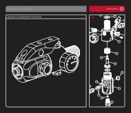
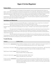
w w w . B o b L o n g D i r e c t . c o m360 ˚ Inline Regulator:Your Protege comes equipped with one of the best high pressure regulators on themarket. To ensure the best consistency and the highest flow possible, it is recommendedthat you clean and relubricate the HPR according to the maintenance schedule.HPR Maintenance:• Degas the marker and ensure that thereare no paintballs in the breech or barrel ofthe marker.• Remove your macroline hose from the 90˚fitting on your regulator• Unscrew your regulator from the Protegevertical adaptor, and set your markerdown.• Grasp the two halves of the regulator, andunscrew the regulator base in a counterclockwise fashion.• Tap the regulator base on a hard, flatsurface to allow the regulator piston,spring stack, spring follower to slide out ofthe regulator base.• Inspect the surface of the piston and oringfor excessive wear or nicks, and replaceas necessary.• Inspect the interior walls of the regulator base—if necessary, use a swab on theinterior of the regulator base to clean debris and old grease.• Regrease the piston with Dow 55, andgently replace the piston, spring stack,and spring follower back into the regulatorbase.Proper Washer Stack Layout:)()()()(16
Protege Low Pressure w Regulator:w w . B o b L o n g D i r e c t . c o mYour Protege comes equipped with one of the best low pressure regulators on the market.To ensure the best consistency and the highest flow possible, it is recommendedthat you clean and relubricate the low according to the maintenance schedule.LPR Maintenance:• Degas your marker and ensure that thereare no paintballs in the breech or barrel ofthe marker.• Remove your macroline hose from the90˚ fitting on your regulator• Unscrew your regulator from the Protegevertical adaptor, and set the verticalregulator down.• Grasp the low pressure regulator to ensurethat it does not eject from the marker uponremoval of its retaining screw.• Remove the LPR retaining screw from inside the Protege vertical adaptor, and allowthe LPR assembly to slide out of the marker.• Remove the brass LPR adjustment screwfrom the LPR assembly by unscrewing it inthe counterclockwise direction.• Remove the LPR cap from the LPR body byunscrewing it in the counterclockwise direction.• Tap the LPR body on a hard, flat surface toallow the LPR piston, spring, and washer toslide out of the regulator base.• Inspect the surface of the piston and oringfor excessive wear or nicks, and replace asnecessary.• Inspect the interior walls of the LPR body—if necessary, use a swab on the interior ofthe LPR body to clean debris and oldgrease.• Regrease the piston with Dow 55, andgently replace the piston, spring stack, andspring follower back into the LPR body.• Replace and tighten the LPR cap, and reinsert the brass LPR adjuster screw.17
Poppet Maintenance:w w w . B o b L o n g D i r e c t . c o m• Degas the marker and ensure that thereare no paintballs in the breech or barrel ofthe marker.• Remove your macroline hose from the 90˚fitting on your regulator• Unscrew your regulator from the Protegevertical adaptor, and set the vertical regulator down.• Grasp the low pressure regulator to ensurethat it does not eject from the marker uponremoval of its retaining screw.• Remove the LPR retaining screw from inside the Protege vertical adaptor, and allowthe LPR assembly to slide out of the marker.• Using a pair of needle nose pliers, removethe poppet return spring and poppet valvefrom the front of the ram sleeve.• Inspect the surface of the poppet and oringfor excessive wear or nicks, and replace asnecessary.• Clean debris and excess grease from thepoppet surface, and regrease the poppet oring with Dow55.• Replace the poppet and poppet returnspring into the ram sleeve, and attach theLPR with the LPR retaining screw.18
Anti Chop Eye Maintenace:w w w . B o b L o n g D i r e c t . c o m1In the event of a chopped ball or debris in thebreech, your Protege eyes may need cleaning.• Remove the eye cover screw, and removethe eye cover.• Carefully unscrew the PCB retaining screw• Gently lift the eye PCB away from the bodyof the marker.• Unplug the main harness from the eye PCB(be careful to not pull on the wires—thiscould potentially damage your harness and\or eye PCB)• Remove the eye PCB for cleaning.• Use a clean cotton swab to clean the surface of the eye, dampen the swab with alcohol if necessary.• You can safely clean the electronic components on eye PCB with canned air as well—however, be careful to not invert the can orapply direct downward pressure on any component.• After the eye has been sufficiently cleaned,reinstall the PCB and reinstall the PCB retaining screw and eye cover.235419
w w w . B o b L o n g D i r e c t . c o mCONSUMABLES LISTPart Name Specifications QuantityXpress Mount ASA Set 8-32x3\16 Cup Point Socket Set Screw 4ScrewsGrip Panel Screws 6-32 x 3\16 Button Head Socket Cap 6ScrewBottom PCB Retaining Screw M2x4mm Pan Head Machine Screw 1Trigger Spring Stop Screws M2x12mm Pan Head Machine Screw 2Trigger Pre-Travel Set Screw 6-32x3\8 Cup-Point Socket Set Screw 1Trigger Post-Travel Set Screw 6-32x1\4 Cup-Point Socket Set Screw 1Rear Grip Frame Screw 10-32x5\16 Button Head Socket Cap 1ScrewDrive Manifold Screw 2-56x1\4” Socket Head Cap Screw 1Rear Bolt Spring Retainer 1\4-28x3\8 Cup-Point Socket Set Screw 1ScrewBolt Pin Detent Ball 3\16" Ball Bearing 1Eye Cover Screw 2-56x1\4” Socket Head Cap Screw 2Eye Board PCB Retaining 2-56x1\4” Flat Head Machine Screw 2ScrewBottom Air Passage Plug M3x3mm Cup-Point Socket Set Screw 1LPR Retaining Screw 10\32 x 1\2 Socket Head Cap Screw 1360˚ Inline Regulator Swivel 10\32x1\4” Cup-Point Socket Set Screw 2Lock Screws360˚ Inline Regulator Adjustment1\4-28x3\8 Cup-Point Socket Set Screw 1ScrewRear Air Passage Plug M3x8mm Cup-Point Socket Set Screw 1Front Air Passage Plug M3x8mm Cup-Point Socket Set Screw 120
w w w . B o b L o n g D i r e c t . c o mO-RING LISTPart Name Specifications Quantity360˚ Inline Regulator Piston Oring 016 Buna (Durameter 70) 1360˚ Regulator ASA Internal Stem 014 Buna (Durameter 70) 2Orings360˚ Regulator ASA Oring 015 Buna (Durameter 70) 1Primary Air Chamber Gasket 028 Buna (Durameter 70) 1LPR Housing Orings 015 Buna (Durameter 70) 3LPR Piston Oring 012 Buna (Durameter 70) 1Bolt Orings 014 Buna (Durameter 70) 3Poppet Shaft Oring 006 Buna (Durameter 70) 1Rear Ram Oring 011 Buna (Durameter 70) 1Front Ram Oring 006 Buna (Durameter 70) 1Drive Manifold Orings 1mm X 3mm Buna (Durameter 70) 2Hose Barb Fitting Seal 1mm X 3mm Buna (Durameter 70) 3Solenoid Manifold Oring 1mm X 4.5 mm Buna (Durameter 70) 1Ram Sleeve Orings 015 Buna (Durameter 70) 5Ram Sleeve Internal Cap Seal 1mm x 14mm Buna (Durameter 70) 121
Marker will not turn on out of the box—Ensure that the battery that you’re using in your new marker is a high quality alkaline 9volt. Verify that your battery is correctly oriented (matching with the correct terminals),and that it is making firm contact with the prongs on the circuit board. Make sure thatthe wiring harness is correctly inserted into the receptacle, and that the on\off pad ismaking contact with the switch on the circuit board.Velocity is inconsistent over the chronograph—Always check that your paintballs are of high quality, and consistent in size, as well asusing a correctly sized barrel. If this does not correct your issue, verify that your verticalregulator and low pressure regulator are lubricated and that their seals are in goodcondition. Replace your battery. Also, inspect the rammer orings for nicks and that it isproperly lubricated.Marker chops paint—Always check that your paintballs are of high quality, and consistent in size, as well asusing a correctly sized barrel. If this does not correct your issue, verify that your verticalregulator and low pressure regulator are lubricated and that their seals are in goodcondition—drop off and regulator inconsistency are almost always the culprit in paintbreakage. Ensure that your detents and bolt face are in good condition, and there isnothing in the breech of the marker. Reset your board settings to factory, and use aforce-fed loader.Marker does not air up after tank is connected—Verify that the pin valve on your tank is outputting pressure to the regulator—sometanks will not work properly with certain ASAs. Attempt airing up the marker with anothertank to see if this remedies the issue.Marker does not display correct LED indicator color when turned on—Ensure that the battery that you’re using in your new marker is a high quality alkaline 9volt. Verify that your battery is correctly oriented (matching with the correct terminals),and that it is making firm contact with the prongs on the circuit board. If that does notcorrect the problem, verify that the breech of the maker is clear of obstructions, the boltis in the back position, and that the eyes are plugged into the harness.Marker is leaking from the ASA—Check the tank oring (015 Urethane) for nicks or tears. If this does not correct the leak,check that the macroline hose is in good condition, and not cut unevenly.22
Marker is leaking from the vertical regulator\HPR—If the leak is coming from the macroline elbow, make sure that the macroline fitting hasbeen secured to the regulator with factory approved thread-sealant (NOT TEFLONTAPE) and that the macroline hose has not been cut unevenly. Also, ensure that you’reusing a low-pressure HPA system, and that your regulator is outputting the correctamount. If your regulator continues to leak after these remedies, replace the piston oringand Schrader valve inside the regulator.Air is leaking from the front of the marker frame—Verify that the racetrack oring in the front of the frame is free of nicks, and has a lightcoat of lubrication to induce swelling. Verify that the screw in the center of the verticalASA is snug, and that there is nothing obstructing your frame from making a tight sealwith the bottom of the body.Air is leaking from the rear of the marker frame—Remove the trigger frame from the marker, and inspect the hose to the solenoid. If itappears worn or pinched, consider replacing the hose. Additionally, on the first generationof Protégé and Vice markers, some frames had insufficient clearance andwould contort the hose in such a manner that would cause some markers to develop aframe leak. If your marker has this issue, replace the hose and apply a small amountof grease to the hose to allow it to compress in the frame without being deformed. Ifthis does not fix your issue, consult expert advice or consider returning the marker toBLAST for service.Marker leaks down the barrel—Ensure that your ram orings are free of nicks, and properly lubricated. Verify that yourpoppet base is in good condition, with its stem oring being free of lacerations and properlylubricated. If this does not correct your issue, consult expert advice or considerreturning the marker to BLAST for service.Marker fires more than one shot per pull, or has trigger bounce—Raise your marker’s debouce level, and make sure that your trigger activation level isnot too short. Also, verify that your trigger has the spring installed and that it is properlyfunctioning. Verify that your marker is in semi-automatic mode.Marker double feeds—Replace the marker’s ball detents.23
BOB LONG TECHNOLOGIES1799 CARPENTER RDOAKLEY, CA 94561925-625-7929techsupport@boblongdirect.comwww.boblongdirect.com