INSTRUKCJA EUROSTER 2020 - Logitron
INSTRUKCJA EUROSTER 2020 - Logitron
INSTRUKCJA EUROSTER 2020 - Logitron

You also want an ePaper? Increase the reach of your titles
YUMPU automatically turns print PDFs into web optimized ePapers that Google loves.
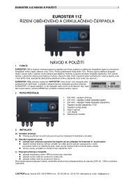
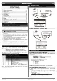
<strong>EUROSTER</strong> 1100K – USER MANUAL 11. APPLICATION<strong>EUROSTER</strong> 1100KEuroster 1100K is a processor-based electronic temperature controller designed forcontrolling the operation of hydronic heating fireplace system.The unit has two outputs controlling:1. circulating pump on the fireplace circuit2. actuated valve or a second circulating pump for efficient operation in combinationwith the hydronic heating circuit.The controller operates the circulating pump on the fireplace circuit and the valve or thesecond pump, depending on the water temperature.The digital sensor measures the temperature of water on the fireplace circuit withoptional splitting into two independent circuits.<strong>EUROSTER</strong> 1100K is equipped with ANTISTOP system, to prevent seizure ofpump rotor in idle periods. Throughout the non-heating season every fortnight theintegral processor of <strong>EUROSTER</strong> 1100K will automatically cycle the pump for 30 seconds.For this function to be operational, the thermostatic controller must NOT be switched offat the end of the heating season.1. Status indication – valve2. Status indication – pump3. Temperature setpoint for the pump, temperature adjustment – up4. Temperature setpoint for the valve, temperature adjustment – down5. On/off switch for continuous pump operation6. On/off mains switch7. Power supply to valve or pump, 230V AC8. Temperature sensor9. Power supply to pump, 230V AC10. Power supply to controller unit, 230V AC2. INSTALLATIONDANGER! Dangerous voltage is present both inside the enclosure and onthe outgoing cables. Prior to installation by a qualified electrician makesure that the unit has been disconnected from power supply to avoid therisk of electric shock. Units with mechanical damage should not beinstalled.a. mounting of the controller:
<strong>EUROSTER</strong> 1100K – USER MANUAL 2• the controller is fixed directly to the wall or to any other support with two screws(plastic plugs c/w screws are part of delivery)• the cables extending from the controller are fixed to the wall with cable clipsb. mounting of the temperature sensor:• the sensor is NOT intended for immersion in liquids and installation onbreechings (flues between the boiler and chimney)• install the heating water temperature sensor on the outside of the fireplace circuitor on the bare outlet pipe from the fireplace (as close to the fireplace as possible)• secure the sensor on the pipe with the supplied fixing clipc. connecting of the power supply cable to the pump:• connect the yellow or yellow/green wire (protective conductor) to terminal ( )• connect the blue wire to terminal (N)• connect the brown wire to terminal (L)d. connecting of the power supply cable to the valve (marked with a bluesleeve):• connect the yellow or yellow/green wire (protective conductor) to terminal ( )• connect the blue wire to terminal (N)• connect the brown wire to terminal (L)e. check-up of connections:• make sure the connections have been made as indicated and secure the cover ofthe pump motor terminal boxf. connection of the controller:• upon securing the cables against accidental pullout, connect the power supplycable to a 230V/50Hz grounding socket.IMPORTANT: At the mounting location of the controller ambient temperature should notexceed 40ºC.3. OPERATIONAfter switching on the controller allow ca. 30 sec. for the controller to becomefully operationala. start up:• set the left-hand toggle switch (~) to position I,• upon energising all the segments of the display light up for 2 seconds,• the current temperature, as measured by the sensor is displayed and thecontroller operates according to the factory settings (temperature limits of 50°C).b. description of display functions• display continuously on – current temperature, as measured by the sensor,• blinking display – temperature setpoint,• red LED on – valve status• green LED on – pump statusc. setting the temperatures• setting the temperature for the valve: press the left-hand switch under the display– the figures will start blinking and the current setpoint will be displayed,• use the right-hand and left-hand switches to increase/ decrease the displayedtemperature setpoint, as appropriate,
<strong>EUROSTER</strong> 1100K – USER MANUAL 3• after ca. 4 sec. the display will stop blinking - this indicates that the presettemperature has been stored. The display will return to displaying the currenttemperature, as measured by the sensor.• setting the temperature for the pump: press the right-hand switch under thedisplay – the figures will start blinking and the current temperature setpoint willbe displayed,• use the right-hand and left-hand switches to increase/ decrease the displayedtemperature setpoint, as appropriate,• after ca. 4 sec. the display will stop blinking - this indicates that the presettemperature has been stored. The display will return to displaying the currenttemperature, as measured by the sensor.d. automatic operation mode• set the right hand switch () to 0• the controller will operate the pump and valve according to the temperaturesetpoint.• in the hydronic heating system the pump is switched on when the temperaturemeasured by the sensor has risen by 2°C above the setpoint and it is switched offwhen the temperature has dropped by 3°C below the setpoint.e. continuous operation mode:• set the toggle switches (~) and () to position I,• the pump is continuously on, irrespective of the selected operating mode (DHW/heating), temperature setpoint and the current temperature, as measured by thesensor.4. COMPLIANCE WITH STANDARDS AND CONFORMITY CERTIFICATES<strong>EUROSTER</strong> 1100K is in compliance with the following EU directives: EMC, LVDThe CE certificate of conformity is posted on our website:www.euroster.com.pl5. DATA SHEETa. temperature setting range 10°C – 80°Cb. temperature measurement range 1°C – 99°Cc. hysteresis (on / off difference) 5°Cd. supply voltage 230V ACe. max. current 6A ACf. length of cables 1.5 mg. dimensions 145x72x456. SHIPPING LISTa) controller and sensorb) fixing clipc) wall plugsd) user manuale) installation template
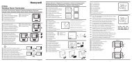
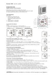
<strong>EUROSTER</strong> 1100K – USER MANUAL 47. WIRING DIAGRAMSThese are simplified diagrams and as such they not show all the components necessaryfor fully functional operation of the system.1. hydronic heating fireplace system2. shutoff valve3. heating water circulating pump4. heat exchanger5. valve or pump6. heating unit - radiator7. expansion vessel8. temperature sensor9. <strong>EUROSTER</strong> 1100K10. heating boiler11. cable marked with a sleeve