Automated Axon Tracking of 3D Confocal Laser Scanning ...
Automated Axon Tracking of 3D Confocal Laser Scanning ...
Automated Axon Tracking of 3D Confocal Laser Scanning ...

You also want an ePaper? Increase the reach of your titles
YUMPU automatically turns print PDFs into web optimized ePapers that Google loves.
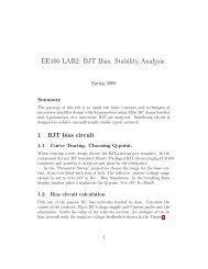
(e)Figure 10 – <strong>Tracking</strong> results in dataset one: (a) The MIP image <strong>of</strong> the dataset, (b) Cross-over in the MIP image(The region inside the yellow rectangle in (a) has been magnified for better visualization), (c) Manual trackingresults, (d) Centerlines in MIP image, and (e) <strong>3D</strong> model <strong>of</strong> the centerlines. The scale bars in (a) and (d) correspondto 6μm. The scale bar in (b) corresponds to 4μm.Approximately 50% <strong>of</strong> the dataset was tracked using the cross-sectional tracking algorithm.The average deviation <strong>of</strong> the centerlines detected by our algorithm from the manually trackedresults was found to be 1.75 pixels.The second dataset contained six axons with 256 cross-sectional images, each having aresolution <strong>of</strong> 43 x 512 pixels. The cross-sectional images were sampled along the X direction.Figure 11(a) shows the MIP image for this dataset. The cross-over <strong>of</strong> the axons in the MIP imageis shown inside the white ellipse in Figure 11(b). The maximum width <strong>of</strong> the axon was set t<strong>of</strong>orty pixels while the resolution <strong>of</strong> the grid for the MIP image was set to fifteen pixels. Figure11(c) shows the manual tracking results for the dataset. The 2D and the <strong>3D</strong> centerlines are shownin Figure 11(d)-(e).26