Variable Displacement Pump A10VSO - Group VH A/S
Variable Displacement Pump A10VSO - Group VH A/S
Variable Displacement Pump A10VSO - Group VH A/S

Create successful ePaper yourself
Turn your PDF publications into a flip-book with our unique Google optimized e-Paper software.
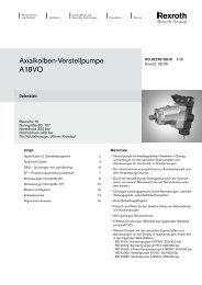
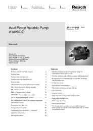
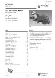
RE 92 711/09.00RE 92 711/09.00replaces: 03.00<strong>Variable</strong> <strong>Displacement</strong> <strong>Pump</strong> <strong>A10VSO</strong>for open circuitsSizes 28...140Series 31Nominal Pressure 280 barPeak pressure 350 barAxial Piston Swashplate Design<strong>A10VSO</strong>...DRIndexFeatures 1Ordering Code / Standard Program 2, 3Fluid, Mechanical <strong>Displacement</strong> Limiter, High-Speed-Version 4Technical Data 5Installation Notes 6Noise Characteristics 7Drive Power and Flow 8, 9Unit Dimensions, Size 28 10Unit Dimensions, Size 45 11Unit Dimensions, Size 71 12Unit Dimensions, Size 100 13Unit Dimensions, Size 140 14Two-position Adjustment Direct Control DG 15Pressure Control DR 16, 17Pressure Control, Remote Controlled DRG 18, 19Pressure / Flow Control DFR 20, 21Pressure / Flow / Power Control DFLR 22, 23Flow Control, Pilot Pressure-dependent FHD 24, 25Through Drives 26Unit Dimensions Combination <strong>Pump</strong>s 27Unit Dimensions Through Drives KB2, K51, KB3 und K25 28, 29Unit Dimensions Through Drives KB4, K26, KB5 und K27 30, 31Unit Dimensions Through Drives KB6, K37, KB7 und K59 32, 33Unit Dimensions Through Drives K01, K52, K02 und K68 34, 35Unit Dimensions Through Drives K04, K07, K24 und K17 36, 37Unit Dimensions Through Drive K57 38Preferred Types 39Features– <strong>Variable</strong> displacement axial piston pump of swashplate designfor hydrostatic open circuit systems– Flow is proportional to drive speed and displacement. It can beinfinitely varied by adjustment of the swashplate.– ISO mounting flange– Flange connections to SAE metric– 2 case drain ports– Good suction characteristics– Permissible continous pressure 280 bar– Low noise level– Long service life– Axial and radial loading of drive shaft possible– High power-weight ratio– Wide range of controls– Short response times– Through drive option for multi-circuit system– Further information:<strong>Variable</strong> <strong>Displacement</strong> <strong>Pump</strong> <strong>A10VSO</strong> RE 92 712Size 18<strong>A10VSO</strong> 1/40
RE 92 711/03.00Ordering Code / Standard ProgramHydraulic Fluid / Type 28...100 140Mineral oil and HFD (no prefix) ● ●HFA, HFB and HFC - Fluids (with the exception of Skydrol) ● ●High-Speed-Version – ●Axial Piston Unit<strong>Variable</strong> swashplate design, for industrial applicationsNominal pressure 280 bar, peak pressure 350 barEHA10VSType of operation<strong>Pump</strong> in open circuitOSize<strong>Displacement</strong> V g max (cm 3 ) 28 45 71* 100 140Control device 28 45 71 100 140Two-position control, direct operated DG ● ● ● ● ●Pressure control DR ● ● ● ● ●DR G ● ● ● ● ●remotely controlledPressure/flow control DFR ● ● ● ● ●DFR 1 ● ● ● ● ●without orifice in X-linePressure/flow/power control ● ● ● ● ●Flow control , pilot pressure dependent ● ● ● ● ●with pressure controlFlow control, electronic ● ● ● ● ❍Pressure/flow control, electronic ● ● ● ● ●Elektro-hydraulic pressure control ● ● ● ❍ ❍** For further control information see RE 30 022DGDRDRGDFRDFR1DFLRFHDFE1**DFE1**EDsee RE 92 707(in preparation)SeriesDirection of rotationViewed on shaft endSealsNBR nitril-caoutchouc to DIN ISO 1629 (shaft seal in FKM)FKM fluor-caoutchouc to DIN ISO 1629clockwiseanti clockwise31RLPVShaft end 28 45 71 100 140Parallel with key DIN 6885 ● ● ● ● ●Splined shaft SAE 7/8" 1" 1 1/4" 1 1/2" 1 3/4"Splined shaft SAE (higher through drive torque) 7/8" 1" 1 1/4" – –PSR* Project note for size 71Pressure port B consists of a high pressure combination portSAE 11/4" standard pressure range, 3000 psi, for pressures up to 250 barSAE 1" standard pressure range, 5000 psi, for pressures in excess of 250 bar (see page 12).For new applications high pressure port SAE 1" must be used.prefered program(short delivery times)see list on page 39● = available❍ = in preparation– = not availableBrueninghaus Hydromatik 2/40 <strong>A10VSO</strong>
RE 92 711/03.00Hydraulic FluidA10VS O / 31 – 12Axial Piston UnitType of operationSizeControl deviceSeriesDirection of rotationSealsShaft endMounting flange 28 45 71 100 140ISO 2-hole ● ● ● ● –ISO 4-hole – – – ❍ ●Service line connectionsPressure port B ⎫ SAE ports at opposite sides⎬Suction port S ⎭ Metric fixing threadAB12Through drives 28 45 71 100 140without through drive ● ● ● ● ●with through drive to accept an axial piston pump, a gear pump or a radial piston pumpMounting flange shaft / coupling for mounting of:ISO 80, 2-hole splined shaft 3/4" 19-4 (SAE A-B) <strong>A10VSO</strong> 10, 18 (shaft S or R) ● ● ● ❍ ❍ISO 80, 2-hole keyed shaft ø18 <strong>A10VSO</strong> 18 ● ● ● ● ●ISO 100, 2-hole splined shaft 7/8" 22-4 (SAE B) <strong>A10VSO</strong> 28 (shaft S or R) ● ❍ ● ● ●ISO 100, 2-hole keyed shaft ø22 <strong>A10VSO</strong> 28 ● ● ● ● ●ISO 100, 2-hole splined shaft 1" 25-4 (SAE B-B) <strong>A10VSO</strong> 45 (shaft S or R) – ● ● ● ●ISO 100, 2-hole keyed shaft ø25 <strong>A10VSO</strong> 45 – ● ● ● ●ISO 125, 2-hole splined shaft 1 1/4" 32-4 (SAE C) <strong>A10VSO</strong> 71 (shaft S or R) – – ● ● ●ISO 125, 2-hole keyed shaft ø32 <strong>A10VSO</strong> 71 – – ● ● ●ISO 125, 2-hole splined shaft 1 1/2" 38-4 (SAE C-C) <strong>A10VSO</strong> 100 (shaft S) – – – ● ●ISO 125, 2-hole keyed shaft ø40 <strong>A10VSO</strong> 100 – – – ● ●ISO 180, 4-hole splined shaft 1 3/4" 44-4 (SAE D) <strong>A10VSO</strong> 140 (shaft S) – – – – ●ISO 180, 4-hole keyed shaft ø45 <strong>A10VSO</strong> 140 – – – – ●82-2(SAE A, 2-hole) splined shaft 5/8" 16-4 (SAE A) 1PF2G2, PGF2 ● ● ● ● ●82-2(SAE A, 2-hole) splined shaft 3/4" 19-4 (SAE A-B) <strong>A10VSO</strong> 10, 18 (shaft S) ● ● ● ● ●101-2(SAE B, 2-hole) splined shaft 7/8" 22-4 (SAE B) 1PF2G3 ● ● ● ● ●101-2 (SAE B) splined shaft 22-4 (SAE B) A10VO 28 (shaft S), PGF3 ● ● ❍ ● ●101-2(SAE B) splined shaft 25-4 (SAE B-B) A10VO 45 (shaft S), PGH4 ● ● ● ● ●127-2 (SAE C) splined shaft 32-4 (SAE C) A10VO 71 (shaft S) – – ● ● ❍127-2 (SAE C) splined shaft 38-4 (SAE C-C) A10VO 100 (shaft S), PGH5 – – – ● ●152-4 (SAE D) splined shaft 44-4 (SAE D) A10VO 140 (shaft S) – – – – ●Ø 63, metr. 4-hole keyed shaft Ø 25 R4 ● ● ● ● ●* Not for new applications, only permissible with reduced through drive torque (see page 26)N00KB2K51*KB3K25*KB4K26*KB5K27*KB6K37*KB7K59*K01K52K02K68K04K07K24K17K57Combination pumps1. If a second Brueninghaus pump is to be fitted at factory then the two model codes must be linked with a"+" sign.Model code 1st pump + Model code 2nd pump.Ordering example: <strong>A10VSO</strong> 100DR/31R-PPA12KB5 + <strong>A10VSO</strong> 71DFR/31R-PSA12N002. If a gear or radial piston pump is to be fitted at factory please consult us.<strong>A10VSO</strong> 3/40 Brueninghaus Hydromatik
RE 92 711/03.00Technical DataHydraulic fluidFor extensive information on the range of fluids and applicationconditions please see our data sheet RE 90220 (mineral oils),RE 90221 (environmentally acceptable fluids) and RE 90223(HF-fire resistant hydraulic fluids).When using HF- or environmentally acceptable hydraulic fluidspossible limitations for the technical data have to be taken intoconsideration. If necessary please consult our technical department(please indicate type of the hydraulic fluid used for your applicationon the order sheet).Operation on Skydrol hydraulic fluid is subject to consultation.Operating viscosity rangeIn order to obtain optimum efficiency and service life, we recommendthat the operating viscosity (at operating temperature) be selectedfrom within the rangeν opt= operating viscosity 16...36 mm 2 /sreferred to the reservoir temperature (open circuit).Viscosity limitsThe limiting values for viscosity are as follows:ν min= 10 mm 2 /sshort term at a max. permissible case temp. of 90° C.ν max= 1000 mm 2 /sshort term on cold start.Temperature range (see selection diagram)t min= – 25° Ct max= 90° CSelection diagramviscosity ν (mm 2 /s)10006004002001008060402015- 20° 0° 20° 40° 60° 80° 100°1000VG 22VG 32VG 68VG 46VG 1001010- 25° - 10° 10° 30° 50° 70° 90° temperaturet min= -25° Ct (° C)t max= +90° Cfluid temperature range36ν opt16Notes on the selection of the hydraulic fluidIn order to select the correct fluid, it is necessary to know the operatingtemperature in the tank (open loop) in relation to the ambienttemperature.The hydraulic fluid should be selected so that within the operatingtemperature range, the operating viscosity lies within the optimumrange (ν opt) (see shaded section of the selection diagram). Werecommend that the higher viscosity range should be chosen in eachcase.Example: At an ambient temperature of X° C the operatingtemperature is 60° C. Within the operating viscosity range (ν opt;shaded area), this corresponds to viscosity ranges VG 46 or VG 68;VG 68 should be selected.Important: The leakage oil (case drain oil) temperature is influencedby pressure and pump speed and is always higher than the tanktemperature. However, at no point in the circuit may the temperatureexceed 90° C.If it is not possible to comply with the above conditions because ofextreme operating parameters or high ambient temperatures pleaseconsult us.FiltrationThe finer the filtration the better the cleanliness of the pressure fluidand the longer the life of the axial piston unit.To ensure the functioning of the axial piston unit a minimumcleanliness level of:9 to NAS 163818/15 to ISO/DIS 4406 is necessary.If above mentioned grades cannot be maintained please consultsupplier.High-speed-versionThe size 140 is available in an optional high speed version. This versionallows higher drive speeds at max. displacement (higher output flow)without affecting outside dimensions, see table on page 5.Mechanical displacement limiterMechanical displacement limiter is possible on the nonthroughdrivemodel, N00 series but not for the model with throughdrive.Exception: with FE1-, FE1D- and DFE1 control a max. displacementscrew is not possible at all.V g max: for sizes 28 to 140Setting range V g maxto 50% V g maxsteplessV g min: for sizes 100 and 140Setting range V g minto 50% V g maxsteplessBrueninghaus Hydromatik 4/40 <strong>A10VSO</strong>
RE 92 711/03.00Installation NotesOptional installation position. The pump housing must be filled withfluid during commissioning and remain full when operating.In order to attain the lowest noise level, all connections (suction,pressure, case drain ports) must be linked by flexible couplings totank.Avoid placing a check valve in the case drain line.This may, however, be permissible in individual cases, after consultationwith us.1. Vertical installation (shaft end upwards)The following installation conditions must be taken into account:1.1. Arrangement in the reservoirBefore installation fill pump housing, keeping it in a horizontal position.a) If the minimum fluid level is equal to or above the pump mountingface close port “L”plugged, leave ports"L 1" and “S” open; L 1pipedand recommendation S piped (see Fig.1).b) If the minimum fluid level is below the pump mounting face pipeport “L 1” and “S” according to Fig. 2.Close port "L" with respect taking into consideration conditions in 1.2.1.Fluid2. Horizontal installationThe pump must be installed, so that "L" or "L 1" is at the top.2.1. Arrangement in the reservoira) If the minimum fluid level is above the top of the pump, port"L 1" closed, "L" and “S” should remain open, L piped andrecommendation S piped (see Fig. 3)b) If the minimum fluid level is equal to or below the top of thepump, pipe ports "L" and possibly "S" as Fig. 4.; close port "L 1".The conditions according to item 1.2.1.LL 1Fluidmin. 200 mmSh t minFig. 3Fig. 11.2. Arrangement outside the reservoirBefore installation fill the pump housing, keeping it in a horizontalposition. For mounting above reservoir see Fig. 2.Limiting condition:1.2.1. Minimum pump inlet pressure p abs min= 0.8 bar under bothstatic and dynamic conditions.Note: Avoid mounting above reservoir wherever possible in order toachieve a low noise level.The permissible suction height h comes from the overall pressureloss, but may not be bigger than h max= 800 mm (immersion depthh t min= 200 mm).h t minh maxL 1SL 1min. 200 mmOverall pressure loss ∆p tot= ∆p 1+ ∆p 2+ ∆p 3≤ (1 – p abs min) = 0.2 bar∆p 1: Pressure loss in pipe due to accelerating column of fluidρ • l • dv∆p 1= • 10 –5 (bar)dt ρ = density (kg/m 3 )l = pipe lenght (m)dv/dt = rate of changein fluid velocity (m/s 2 )∆p 2: Pressure loss due to static head∆p 2= h • ρ • g • 10 –5 (bar)∆p 3: Line losses (elbows etc.)SBaffleLFluidLh = height (m)ρ = density (kg/m 3 )g = gravity = 9.81 m/s 2Fig. 22.2. Installation outside the reservoirFill the pump housing before commissioning.Pipe ports "S" and the higher port "L" or "L 1".a) When mounting above the reservoir, see Fig. 4.Conditions according to 1.2.1.LL 1b) Mounting below the reservoirPipe ports "L 1" and “S” according to Fig.5, close port "L".BaffleBaffleL 1FluidFluidLh maxh t minh t minSSFig. 4Fig. 5Brueninghaus Hydromatik 6/40 <strong>A10VSO</strong>
RE 92 711/03.00Performance Curves for <strong>Pump</strong> with Pressure Control DRNoise levelMeasured in an anechoic chamberDistance from microphone to pump = 1 mMeasuring error: ± 2 dB (A)(Fluid: Hydraulic oil to ISO VG 46 DIN 51519, t = 50° C)Size 28 Size 100noise level L A[dB(A)]56640 50 100 150 200 250 280operating pressure p [bar]6260Size 45076 q v max74q v Null zero72q Size 14070n = 2600 min -1v maxq v Null zero 8468n = 1500 min -1826680647862766074580 50 100 150 200 250 28072operating pressure p [bar]7068Size 7166noise level L A[dB(A)]noise level L A[dB(A)]74q v max72q v Null zero70q68n = 3000 min -1v maxq v Null zero66n = 1500 min -16462605880q v max6478q 62v Null zero7660740n = 2200 min -1q v72max70q v Null zero68n = 1500 min -166646260580 50 100 150 200 250 280operating pressure p [bar]noise level L A[dB(A)]noise level L A[dB(A)]8280787674727068665050n = 2000 min -1n = 1500 min -1100 150 200q v maxq v Null zeroq v maxq v Null zero250 280operating pressure p [bar]q v maxq v maxn = 1800 min -1 q v Null zeroq v Null zeron = 1500 min -1100 150 200 250 280operating pressure p [bar]<strong>A10VSO</strong> 7/40 Brueninghaus Hydromatik
RE 92 711/03.00Drive Power and Output Flow(Fluid: Hydraulic oil ISO VG 46 DIN 51519, t = 50° C)Size 28– – – – n = 1500 min –1_____ n = 3000 min–1Size 45– – – – n = 1500 min –1_____ n = 2600 min–1flow q v[L/min]flow q v[L/min]120100908080604020604020q vP qv Null zero0 50 100 150 200 250 280q voperating pressure p [bar]P qv zero NullP qv maxP qv max403020106050403020100drive power P [kW] drive power P [kW]00 50 100 150 200 250 280operating pressure p [bar]Size 7116080– – – – n = 1500 min –1_____ n = 2200 min–1flow q v[L/min]1401201008060q vP qv max7060504030drive power P [kW]402020P qv zero Null1000 50 100 150 200 250 280operating pressure p [bar]Brueninghaus Hydromatik 8/40 <strong>A10VSO</strong>
RE 92 711/03.00Unit Dimensions Size 28N00 model (without through drive)without control valvesBefore finishing your design, please request a certified drawing.Shaft PISO 3019/22 hole flange2 3296,390LVB45°45°L2614ø100 h8ø22 j6M6801746h8807524,5-0,174161310 40L146 164206SWmech. displacementlimiter83,5ø140ø164L1Shaft SShaft 22-4; (SAE B)SAE J744 OCT 83View Wø7/8"1/4-20UNC-2B1625,1pressure angle 30°,13 teeth,16/32 pitch58,7ø3230,2SM10; 17 deep33,141View VShaft RShaft 22-4; (SAE B)SAE J744 OCT 8347,6ø2022,2BM10; 17 deepø7/8”1/4-20UNC-2B16pressure angle 30°,13 teeth,16/32 pitchø32useful spline length2541B Pressure port SAE 3/4" (Standard pressure range)S Suction port SAE 1 1/4" (Standard pressure range)L/L 1Case drain ports M18x1,5 (L 1plugged at factory)Brueninghaus Hydromatik 10/40 <strong>A10VSO</strong>
RE 92 711/03.00Unit Dimensions Size 45N00 model (without through drive)without control valvesBefore finishing your design, please request a certified drawing.Shaft PISO 3019/22 hole flange3 3696,396LVB45°45°L2614908h9ø100 h8ø25 j6M8199080,528 -0,28313L110 4552 184224SWmech. displacementlimiter93,5ø140ø184L1Shaft SShaft 25-4; (SAE B-B)SAE J744 OCT 83View Wø1"1/4-20UNC-2B1630pressure angle 30°,15 teeth,16/32 pitch69,9ø4035,7SM12; 20deep3845,9View VShaft R52,4ø25BShaft 25-4; (SAE B-B)SAE J744 OCT 83ø1”1/4-20UNC-2Bpressure angle 30°,15 teeth,16/32 pitch26,2M10; 17deepuseful spline length1629.545.9B Pressure port SAE 1" (Standard pressure range)S Suction port SAE 1 1/2" (Standard pressure range)L/L 1Case drain ports M22x1,5 (L 1plugged at factory)<strong>A10VSO</strong> 11/40 Brueninghaus Hydromatik
RE 92 711/03.00 711/09.00Unit Dimensions Size 71N00 model (without through drive)without control valvesBefore finishing your design, please request a certified drawing.Shaft PISO 3019/22 hole flange2,5 4596115LVB45°45°L3318ø125 h8ø32 j6M1010410h91049235-0,2229817L110 5360 217259SWmech. displacementlimiter107,5ø180ø210L1Shaft SShaft 32-4; (SAE C)SAE J744 OCT 83ø1 1/4"5/16-18UNC-2BShaft RShaft 32-4; (SAE C)SAE J744 OCT 83ø1 1/4"5/16-18UNC-2B19193851,658,739,547,555,4pressure angle 30°,14 teeth,12/24 pitchpressure angle 30°,14 teeth,12/24 pitchuseful spline length58,726,277,8ø50View W42,9View Vø2530,252,4SM12; 20 deepfixing hole thread M10; 17 deepfor SAE 1"Bfixing hole thread M10; 17 deepfor SAE 1 1/4"Note:At pressure port B there are two SAE mountings available, each offset by 90°.SAE 1 1/4" Standard pressure range, 3000 psi, for pressures up to 250 bar orSAE 1" Standard pressure range, 5000 psi, for pressures in excess of 250 bar.For operating pressures in excess of 250 bar or for new projects an SAE 1" pressureflange should be used.B Pressure port SAE 1" (Standard pressure range) bolt hole threads to either SAE 1" or SAE 1 1/4" (optional)S Suction port SAE 2" (Standard pressure range)L/L 1Case drain ports M22x1,5 (L 1plugged at factory)Brueninghaus Hydromatik 12/40 <strong>A10VSO</strong>
RE 92 711/03.00Unit Dimensions Size 100N00 model (without through drive)without control valvesBefore finishing your design, please request a certified drawing.Shaft PISO 3019/22 hole flange1,5 6896175LVB10645°Lø125 h8ø40 k6M1210015243-0,212h910017,5951022820L110 9580 275SWmech. displacementlimiter180210L1329118Shaft SShaft 38-4; (SAE C-C)SAE J744 OCT 83ø1 1/2"7/16-14UNC-2B2843,6pressure angle 30°,17 teeth,12/24 pitch5461,9View WView Vmech. displacementlimiter max.mech. displacementlimiter min.88,9ø60S66,7ø32BM12; 17 deep M14; 19 deep50,8mech. displacementlimiter min.31,8mech. displacementlimiter max.B Pressure port SAE 1 1/4" (High pressure range)S Suction port SAE 2 1/2" (Standard pressure range)L/L 1Case drain ports M27x2 (L 1plugged at factory)<strong>A10VSO</strong> 13/40 Brueninghaus Hydromatik
RE 92 711/03.00Unit Dimensions Size 140N00 model (without through drive)without control valvesBefore finishing your design, please request a certified drawing.Shaft PISO 3019/24 hole flange1,5 8096,4173LVB118,545°Lø180 h8ø45 k6M16110200110158,448,5-0,214h91081133621 L110 7892 275337,5SWmech. displacementlimiterø18131158,4200L1Shaft SShaft 44-4; (SAE D)SAE J744 OCT 83ø1 3/4"5/8-11UNC-2B36556775pressure angle 30°,13 teeth,8/16 pitchView WView Vmech. displacementlimiter max.mech. displacementlimiter min.88,9ø63S66,7ø32BM12; 17 deepM14; 19 deep50,8mech. displacementlimiter min.31,8mech. displacementlimiter max.B Pressure port SAE 1 1/4" (High pressure range)S Suction port SAE 2 1/2" (Standard pressure range)L/L 1Case drain ports M27x2 (L 1plugged at factory)Brueninghaus Hydromatik 14/40 <strong>A10VSO</strong>
RE 92 711/03.00DG 2-position adjustment, direct controlThe pump can be set to a minimum swivel anle by connecting anexternal switching pressure to port X.This pressure acts directly onto the control piston, a min. controlpressure of at least 30 bar is required.The pump can only be switched between V gmaxand V gmin.The switching pressure p Stdepends on pump output pressure at a ratio of 1:4p St= ____ p4switching pressure p Stin X = 0 bar= ^ V gmaxswitching pressure p Stin X ≥ 30 bar or ____ p ^ = Vgmin4Before finishing your design, please request a certified drawing.BXController datamin. switching pressuremax. switching pressure30 bar280 barS L1 LUnit dimensionsSizes 28...100A 1Bport foranti-clockwise rotationport forclockwise rotationXSA 1BXA4A4A 2A 3Size 140port foranti-clockwise rotationport forclockwise rotationUnit dimensionsSize A 1A 2A 3A 4X (plugged)28 158 100 103,5 3 R 1/4"45 173 110 113,5 3 R 1/4"71 201 123,5 127,5 3 R 1/4"100 268 128,5 132,5 3 R 1/4"140 268 153 158 4,6 M14x1,5SPortsBPressure portSSuction portL, L1 Case drain ports (L1 plugged)XPilot pressure port (plugged)A 2A 3<strong>A10VSO</strong> 15/40 Brueninghaus Hydromatik
RE 92 711/03.00DR Pressure ControlThe pressure controller serves to maintain a constant pressure in ahydraulic system within the control range of the pump. The pumptherefore supplies only the amount of hydraulic fluid required by thesystem. Pressure may be steplessly set at the control valve.BStatic operating curve(at n 1= 1500 rpm; t oil= 50° C)hysteresis and pressure rise ∆pq v maxflow q vq v minadjustment range20 280operating pressure p [bar]Dynamic operating curvesThe operating curves are mean values measured under test conditionswith the unit mounted inside the tank.Conditions: n = 1500 rpmt oil= 50° CMain relief set at 350 barLoad steps were obtained by suddenly opening and closing thepressure line with a pressure relief valve as load valve 1 m from theoutput flange of the pump.S L1 LPortsB Pressure portS Suction portL, L1 Case drain ports ( L1 plugged)350operating pressure p [bar] ➝displacement ➝(swivel angle)300250200150100500VgmaxVgmincontrol time tController dataHysteresis and repetitive accuracy ∆p __________ max. 3 barMax. Pressure riseSize 28 45 71 100 140∆p bar 4 6 8 10 12Pilot oil requirement _________________ max. approx 3 L/minFlow loss at q vmaxsee pages 8 and 9.Control timesSizet SA(ms) t SA(ms) t SE(ms)against 50 bar against 220 bar stalled at 280 bar28 60 30 2045 80 40 2071 100 50 25100 125 90 30140 130 110 30swivel out time t SAswivel in time t SEBrueninghaus Hydromatik 16/40 <strong>A10VSO</strong>
RE 92 711/03.00Unit Dimensions Pressure Control DRBefore finishing your design, please request a certified drawing.Sizes 28…100BControl valve installed herefor anti-clockwise rotationadjustment screw forpressure cut offControl valve installed herefor clockwise rotationA1SA 2On sizes 28 to 100 the DFR valve used has the flow control spoolblocked in the factory and is not tested.Size 140control valve installed herefor anti-clockwise rotationcontrol valve installed herefor clockwise rotationBadjustment screw forpressure cut offA1SA 2Size A 1A 228 109 13645 106 14671 106 160100 106 165140 127 169<strong>A10VSO</strong> 17/40 Brueninghaus Hydromatik
RE 92 711/03.00DRG Pressure Controller, Remote ControlFunction and equipment as for DR.A pressure relief valve can be connected to port X for remote controlapplications; this is not included in the items supplied with the DRGcontrol.The standard pressure differential setting at the control valve is20 bar. A pilot oil flow of approx. 1,5 L/min is then used. If another setting (range 10-22 bar) is required please indicate in cleartext.We recommend the following as separate pressure relief valves:DBDH 6 (hydraulic) to RE 25402 orDBETR -SO 381 with orifice ø0,8 in P (electric) to RE 29166.The max. pipe length should not exceed 2m.Sizes 28…100Bgehört nichtzum not included Lieferumfang in supplyXStatic Operating Curve(at n 1= 1500 rpm; t oil= 50° C)hysteresis and pressure rise ∆pq v maxS L1 Ldisplacement q vadjustment rangeSize 140gehört nichtzumnotLieferumfangincluded in supplyq v min20 280operating pressure p [bar]XController dataHysteresis ∆p _____________________________ max. 3 barMax. pressure riseSize 28 45 71 100 140∆p bar 4 6 8 10 12Pilot oil requirement _____________________ approx. 4,5 L/minBFlow loss at qv maxsee pages 8 and 9.S L1 LPortsBPressure portSSuction portL, L1 Case drain ports ( L1 plugged)XPilot pressure portBrueninghaus Hydromatik 18/40 <strong>A10VSO</strong>
RE 92 711/03.00Unit Dimensions Pressure Controller with Remote Control DRGBefore finishing your design, please request a certified drawing.Size 28…100control valve installed herefor anti-clockwise rotationcontrol valve installed herefor clockwise rotationA 5Badjustment screw forpressure cut offadjustment screw fordifferential pressureXXthreaded connection7/16-20 UNF-2BSA 3A 2Size 140Bcontrol valve installed herefor anti-clockwise rotationcontrol valve installed herefor clockwise rotationadjustment screw fordifferential pressureA 5A 2XXA1A4A4A1SA 3Size A 1A 2A 3A 4A 5Port X28 109 136 119 40 119 M14x1,5; 12 deep}45 106 146 129 40 134 M14x1,5; 12 deepwith adaptor71 106 160 143 40 162 M14x1,5; 12 deep100 106 165 148 40 229 M14x1,5; 12 deep140 127 169 143 27 244 M14x1,5; 12 deep without adaptor<strong>A10VSO</strong> 19/40 Brueninghaus Hydromatik
RE 92 711/03.00DFR/DFR1 Pressure / Flow ControlIn addition to the pressure control function, the pump flow may bevaried by means of a differential pressure over an orifice or valvespool,Xinstalled in the service line. The pump flow is equal to the actualrequired flow by the actuator.not includedThe DFR1-valve has no connection between X and the tank.in supplyFor function of pressure control see pages 16/17.plugged ontswivel out time t SAswivel in time t Flow loss at qSE vmaxsee page 8 and 9.DFR1Static operating curve(at n 1= 1500 rpm; t oil= 50° C)Bq v maxadjustment rangeq v min20 280operating pressure p [bar]PortsS L1 LStatic operating curve at variable speedBPressure portSSuction portL, L1 Case drain ports ( L1 plugged)XPilot pressure portDifferential pressure ∆p:Adjustable between 10 and 22 bar (higher values on request).Standard setting: 14 bar. If a different setting is required please indicatespeed nin clear text.When port X is unloaded to tank a "zerostroke pressure" ofDynamic flow control operating curvep = 18 ± 2 bar ("stand by") results (dependent on ∆p).The operating curves are average values measured under testconditions with the unit mounted inside the tank.100350300280 Controller data75250 Data pressure controller see page 16.200 Max. flow variation (hysteresis and increase)50150measured at drive speed n = 1500 rpm25100 Size 28 45 71 100 14050∆qv maxL/min 1,0 1,8 2,8 4,0 6,0018DFR pilot oil consumption _________ max. approx. 3 ... 4,5 L/mincontrol timeDFR1 pilot oil consumption _____________ max. approx. 3 L/minflow q vdisplacement V g% ➝flow q v∆q v(see table)∆q v(see table)load pressure [bar] ➝(stand by)NGt SA[ms] t SE[ms] t SEstand by–280 bar 280 bar–stand by 50 bar–stand by28 40 20 4045 50 25 5071 60 30 60100 120 60 120140 130 60 130Brueninghaus Hydromatik 20/40 <strong>A10VSO</strong>
RE 92 711/03.00Unit Dimensions DFR; DFR1 Pressure and Flow ControlBefore finishing your design, please request a certified drawing.Sizes 28…100A 5Bcontrol valve installed herefor anti-clockwise rotationadjustment srew pressurecontroller cut-off pressurecontrol valve installed herefor clockwise rotationadjustment srew for flowcontroller differential pressureXXA4X orifice pluggedon DFR1A1SA 2A 5XBA4A1threaded connection7/16-20 UNF-2BA 3Size 140control valve installed herefor anti-clockwise rotationcontrol valve installed herefor clockwise rotationadjustment srew for flowcontroller differential pressureadjustment srew pressurecontroller cut-off pressureX X orificeplugged onDFR1SA 3A 2NG A 1A 2A 3A 4A 5port X28 109 136 119 40 119 M14x1,5; 12 deep45 106 146 129 40 134 M14x1,5; 12 deep}with adaptor71 106 160 143 40 162 M14x1,5; 12 deep100 106 165 148 40 229 M14x1,5; 12 deep140 127 209 183 27 244 M14x1,5; 12 deep without adaptor<strong>A10VSO</strong> 21/40 Brueninghaus Hydromatik
RE 92 711/03.00DFLR Pressure / Flow / Power ControlIn order to achieve a constant drive torque with a varying operatingpressure, the swivel angle and with it the output flow of the axialpiston pump is varied so that the product of flow and pressure remainsconstant.Constant flow control is possible below the power curve.not includedin supplyXStatic operating curvemaximumpower curveB100Power valveFlow q v[%]755025minimalpower curve0 50 100 150 200 250 280 300operating pressure p [bar]S L1 LPortsBPressure portSSuction portL, L1 Case drain ports ( L1 plugged)XPilot pressure portThe power curve is set at the factory, please state your requirementsin clear text e.g. 20 kW at 1500 rpm.Controller dataTechnical data constant pressure control see page 16.Technical data flow control see page 20.Start of control ______________________________ ab 80 barPilot oil requirement _________________ max. approx. 5,5 L/minFlow loss at q vmaxsee pages 8 and 9.Brueninghaus Hydromatik 22/40 <strong>A10VSO</strong>
RE 92 711/03.00Unit Dimensions Pressure / Flow / Power Control DFLRBefore finishing your design, please request a certified drawing.Sizes 28…100Power valvecontrol valve installed herefor anti-clockwise rotationcontrol valve installed herefor clockwise rotationadjustment srew pressurecontroller cut-off pressureA 5A 3A6BXadjustment srew forflow controllerdifferential pressureA4A1thread connection7/16-20 UNF-2BSA 2Size 140Power valvecontrol valve installed herefor anti-clockwise rotationcontrol valve installed herefor clockwise rotationadjustment srew pressurecontroller cut-off pressureBA 5A 2A 3adjustment srewfor flow controllerdifferential pressureXA1A4A6SNG A 1A 2A 3A 4A 5A 6Port X28 109 136 119 40 197 107 M14x1,5; 12 deep45 106 146 129 40 212 112 M14x1,5; 12 deep71 106 160 143 40 240 124 M14x1,5; 12 deep100 106 165 148 40 307 129 M14x1,5; 12 deep140 127 209 183 27 314 140 M14x1,5; 12 deep<strong>A10VSO</strong> 23/40 Brueninghaus Hydromatik
RE 92 711/03.00FHD Pilot Pressure Dependent Flow Control with Pressure Cut-offThe swivel angle of the pump and therefore its displacement isdependent on the pilot pressure p St Xpresent in port X.A constant pressure of p y= 35 bar must be applied to port Y. Theintegral pressure control is steplessly adjustable.(Please state set value required in clear text).MStYXController dataHysteresis ± 2 % of V g maxExternal pilot oil consumption in Y ____ max. approx. 3 ... 4,5 L/minPressure rise ∆p______________________________max. 4 barFlow loss at q vmaxsee pages 8 and 9.PortsBPressure portSSuction portL, L1 Case drain port ( L1 plugged)X, Y Pilot pressure portsMStTest portBS L1 LStatic curve(at n 1= 1500 rpm; t oil= 50° C)hysteresis and pressure rise ∆p<strong>Displacement</strong> V g/ V gmax[%]adjusment range18 12 6 20 280pilot pressure p St[bar]operating pressure p [bar]Brueninghaus Hydromatik 24/40 <strong>A10VSO</strong>
XRE 92 711/03.00Unit Dimensions FHD Pilot Pressure Dependent Flow Control with Pressure Cut-offSizes 28…100Before finishing your design, please request a certified drawing.A 5pilot valve installed herefor anti-clockwise rotationpilot valve installed herefor clockwise rotationadjustment srew pressurecontroller cut-off pressureA 7A 3BYA6A1A8XA10A4thread connection7/16-20 UNF-2BMStSA 9A 12A 2A 11Size 140pilot valve installed herefor anti-clockwise rotationpilot valve installed herefor clockwise rotationA 5adjustment srew pressurecontroller cut-off pressureBYA 9A 3A6XA 7A 12A1A4A8XA10SA 11A 2NG A 1A 2A 3A 4A 5A 6A 7A 8A 9A 10A 11A 12Port X Port Y M St28 109 136 119 40 119 107 48 86 51 113 158 124 M14x1,5 M14x1,5 Pipe dia ø8x1,5 DIN 239145 106 146 129 40 134 112 54 91,5 51 113 173 134 M14x1,5 M14x1,5 Pipe dia ø8x1,5 DIN 239171 106 160 143 40 162 124 69 103,5 51 113 201 148 M14x1,5 M14x1,5 Pipe dia ø8x1,5 DIN 2391100 106 165 148 40 229 129 111 108,5 51 113 268 153 M14x1,5 M14x1,5 Pipe dia ø8x1,5 DIN 2391140 127 209 183 27 244 140 99 119 51 150 268 183 M14x1,5 M14x1,5 Pipe dia ø8x1,5 DIN 2391<strong>A10VSO</strong> 25/40 Brueninghaus Hydromatik
RE 92 711/03.00Through driveThe <strong>A10VSO</strong> pump can be supplied with through drive in accordancewith the type code on page 3.The through drive version is designated by the code numbers (KB2–K57).If no other pumps are fitted by the manufacturer, the simple typedesignation is sufficient.in this case, the delivery package comprises:Hub, fixing screws, seal and, if necessary, an adaptor flange.Combination pumpBy building on further pumps it is possible to obtain independentcircuits:1. If the combination pump consists of 2 <strong>A10VSO</strong> and if these are to besupplied assembled then the two order codes should be linkedby means of a „+“ sign.Ordering example:<strong>A10VSO</strong> 71 DR/31 L–PPA12KB3 +<strong>A10VSO</strong> 28 DR/31 L–PSA12N002. If a gear or radial piston pump is to be built on at the factory,please consult us.Maximum permissible input and through drive torquePermissible moment of inertial 1l 2l 3m 1, m 2, m 3[kg] <strong>Pump</strong> massl 1, l 2, l 3[mm] Distance to center of gravity1T m= (m 1• l 1+ m 2• l 2+ m 3• l 3) •102[Nm]m 1 m 2 m 3Size 28 45 71 100 140Permissible moment of inertia T mNm 880 1370 2160 3000 4500Permissible moment of inertia T mNm 88 137 216 300 450at dynamic mass acceleration10g 98.1 m/sec 2Mass m 1kg 15 21 33 45 60To center of gravity l 1mm 110 130 150 160 160T totT DThe split in torque between pump 1 and 2 is optional. The max.permissible input torque T totas well as the max. permissible throughdrivetorque TDmay not be exceeded.Size 28 45 71 100 140Max. permissible input torque at pump 1 with shaft "P"T totNm 137 200 439 857 1206T DNm 137 200 439 778 1206Max. permissible through-drive torqueTDkeyed shaftNm 112 179 283 398 557Size 28 45 71 100 140Max. permissible input torque at pump 1 with shaft"S"T totNm 198 319 626 1104 1620T DNm 160 319 492 778 1266Max. permissible through-drive torqueTDkeyed shaftNm 112 179 283 398 557Size 28 45 71 100 140Max. permissible input torque at pump 1 with shaft"R"T totNm 225 400 644 – –T DNm 176 365 548 – –Max. permissible through-drive torqueTDkeyed shaftNm 112 179 283 – –T tot= Max. permissible input torque at pump 1T D= Max. permissible through-drive torque at through-driveto splined shaftT D keyed shaft= Max. permissible through-drive torque at through-driveto keyed shaftBrueninghaus Hydromatik 26/40 <strong>A10VSO</strong>
RE 92 711/03.00Unit Dimensions: Combination <strong>Pump</strong>sBefore finishing your design, please request a certified drawing.<strong>A10VSO</strong> + <strong>A10VSO</strong>A1A2A3A4main p. <strong>A10VSO</strong> 28 <strong>A10VSO</strong> 45 <strong>A10VSO</strong> 71 <strong>A10VSO</strong> 100 <strong>A10VSO</strong> 140built-on p. A 1A 2A 3A 4A 1A 2A 3A 4A 1A 2A 3A 4A 1A 2A 3A 4A 1A 2A 3A 4<strong>A10VSO</strong> 18 164 204 349 399 184 229 374 424 217 267 412 462 275 338 483 533 275 350 495 545<strong>A10VSO</strong> 28 164 204 368,5 410 184 229 393,5 435 217 267 431,5 473 275 338 502,5 544 275 350 514 556<strong>A10VSO</strong> 45 – – – – 184 229 413 453 217 267 451 491 275 338 522 562 275 350 534 574<strong>A10VSO</strong> 71 – – – – – – – – 217 267 484 524 275 338 555 595 275 350 567 609<strong>A10VSO</strong> 100* – – – – – – – – – – – – 275 338 613 664 275 350 625 679<strong>A10VSO</strong> 140* – – – – – – – – – – – – – – – – 275 350 625 688* Values with through drive KB6 or KB7 (splined shaft)<strong>A10VSO</strong> 27/40 Brueninghaus Hydromatik
RE 92 711/03.00Unit Dimensions Through Drives KB2 and K51Before finishing your design, please request a certified drawing.Flange ISO 80, 2-hole for built-on <strong>A10VSO</strong> 10 (splined shaft S, mounting flange A, see RD 92713) or<strong>A10VSO</strong> 18 (splined shaft S or R, mounting flange A, see RD 92712)Order code KB2section A - BA45°3818,6splined coupling19-4 (SAE A-B)3/4", 16/32 DP; 11 Tø109ø80 +0.050+0.020B10A 3M10to pump mounting flange A 1Size main pump A 1A 318 (see RD 92712) 182 14,528 204 1645 229 1671 267 20For operation with HF-fluids please consider RE-data sheet of builtonpump.Flange ISO 80, 2-hole for built-on <strong>A10VSO</strong> 10 (shaft P, flange A, see RD 92713) or<strong>A10VSO</strong> 18 (shaft P, flange A, see RD 92712)Order code K51*section A - BSize main pump A 1A 3A 418 (see RD 92712) 182 14,5 3328 204 16 3745 229 16 4371 267 20 51100 338 20 55140 350 20 67to pump mounting flangeFor operation with HF-fluids please consider RE-data sheet of builtonpump.*not for new applications, only permitted with reduced through drivetorques, see page 26.Brueninghaus Hydromatik 28/40 <strong>A10VSO</strong>
RE 92 711/03.00Unit Dimensions Through Drives KB3 and K25Before finishing your design, please request a certified drawing.Flange ISO 100, 2-hole for built-on <strong>A10VSO</strong> 28 (splined shaft S or R);Order code KB345°section A - BA 41A 2splined coupling22-4 (SAE B)7/8", 16/32 DP; 13 Tø140ø100 +0.050+0.020B10A 3M12to pump mounting flange A 1Size main pump A 1A 2A 328 204 19,2 1471 267 16,5 18100 338 17,6 18140 350 18,2 24Flange ISO 100, 2-hole for built-on <strong>A10VSO</strong> 28 (keyed shaft P)Order code K25*section A - BSize main pump A 1A 3A 428 204 14 3745 229 14 4371 267 23 51100 338 20 55140 350 24 62to pump mounting flange*not for new applications, only permitted with reduced through drivetorques, see page 26.<strong>A10VSO</strong> 29/40 Brueninghaus Hydromatik
RE 92 711/03.00Unit Dimensions Through Drives KB4 and K26Before finishing your design, please request a certified drawing.Flange ISO 100, 2-hole for built-on <strong>A10VSO</strong> 45 (splined S or R);order code KB4section A - B45°A 45,9A 2splined coupling25-4 (SAE B-B)1", 16/32 DP; 15 Tø140ø100 +0.050+0.020B10A 3M12to pump mounting flange A 1Size main pump A 1A 2A 345 229 17,2 1471 267 17,2 18100 338 18,2 20140 350 18,2 24Flange ISO 100, 2-hole for built-on <strong>A10VSO</strong> 45 (keyed shaft P)order code K26*section A - Bto pump mounting flangeSize main pump A 1A 3A 445 229 14 4371 267 23 51100 338 20 56140 350 24 67*not for new applications, only permitted with reduced through drivetorques, see page 26.Brueninghaus Hydromatik 30/40 <strong>A10VSO</strong>
RE 92 711/03.00Unit Dimensions Through Drives KB5 and K27Before finishing your design, please request a certified drawing.Flange ISO 125, 2-hole for built-on <strong>A10VSO</strong> 71 (splined shaft S or R);Order code KB5omitted on size 7145°ASchnitt A - B58,7A 2splined coupling32-4 (SAE C)1 1/4", 12/24 DP; 14 Tø180ø125 +0.050+0.020Bomitted on size 7110A 3M16to pump mounting flange A 1Size main pump A 1A 2A 371 267 20 18,5100 338 20 25140 350 21 32Flange ISO 100, 2-hole for built-on <strong>A10VSO</strong> 71 (keyed shaft P)order code K27*section A - Bto pump mounting flangeSize main pump A 1A 3A 471 267 18 51100 338 20 54140 350 24 63*not for new applications, only permitted with reduced through drivetorques, see page 26.<strong>A10VSO</strong> 31/40 Brueninghaus Hydromatik
RE 92 711/03.00Unit Dimensions Through Drives KB6 and K37Before finishing your design, please request a certified drawing.Flange ISO 125, 2-hole for built-on <strong>A10VSO</strong> 100 (splined shaft S);Order code KB6section A - B45°AA 49splined coupling38-4 (SAE C-C)1 1/2", 12/24 DP; 17 Tø180ø125 +0.050+0.020B10A3to pump mounting flange A 1Size main pump A 1A 3A 4100 338 M16; 25 deep 65140 350 M16; 32 deep 77,3Flange ISO 125, 2-hole for built-on <strong>A10VSO</strong> 100 (keyed shaft P)Order code K37*section A - BM16, 20 deepto pump mounting flangeSize main pump A 1A 4100 356 71140 368 80*not for new applications, only permitted with reduced through drivetorques, see page 26.Brueninghaus Hydromatik 32/40 <strong>A10VSO</strong>
RE 92 711/03.00Unit Dimensions Through Drives KB7 and K59Before finishing your design, please request a certified drawing.Flange ISO 180, 4-hole for built-on <strong>A10VSO</strong> 140 (splined shaft S);Order code KB7main pump NG 140A158.4section A - B77.310splined coupling44-4 (SAE D)1 3/4", 8/16 DP; 13 T158.4ø180 +0.05+0.02BM16to pump mounting flange 35010Flange ISO 180, 4-hole for built-on <strong>A10VSO</strong> 140 (keyed shaft P)order code K59*main pump NG 140section A - Bto pump mounting flange*not for new applications, only permitted with reduced through drivetorques, see page 26.<strong>A10VSO</strong> 33/40 Brueninghaus Hydromatik
RE 92 711/03.00Unit Dimensions Through Drives K01 and K52Before finishing your design, please request a certified drawing.Flange SAE 82-2 (SAE A, 2-hole) for built-on external gear pump 1 PF2G2 (see RD 10030) orinternal gear pump PGF2 (shaft J, flange U2, see RD 10213)Order code K01section A - BA45°A 49splined coupling16-4 (SAE A)5/8" 16/32 DP; 9 Tø106.5ø82.55 +0.050+0.020BA 5to pump mounting flange A 110Size main pump A 1A 4A 528 204 47 M10; 16 deep45 229 53 M10; 16 deep71 267 61 M10; 20 deep100 338 65 M10; 20 deep140 350 77 M10; 20 deepFor operation with HF-fluids please consider RE-data sheet of builtonpump.Flange SAE 82-2 (SAE A, 2-hole) for built-on <strong>A10VSO</strong> 10 (shaft S, flange C, see RD 92713) or<strong>A10VSO</strong> 18 (shaft S, flange C, see RD 92712)Order code K52A45°section A - BA 49splined coupling19-4 (SAE A-B)3/4" 16/32 DP; 11 Tø106.5ø82.55 +0.050+0.020BA 5to pump mounting flange A 110Size main pump A 1A 4A 528 206 47,3 M10; 16 deep45 229 53,4 M10; 16 deep71 267 61,3 M10; 20 deep100 338 65 M10; 20 deep140 350 77 M10; 20 deepFor operation with HF-fluids please consider RE-data sheet of builtonpump.Brueninghaus Hydromatik 34/40 <strong>A10VSO</strong>
RE 92 711/03.00Unit Dimensions Through Drives K02 and K68Before finishing your design, please request a certified drawing.Flange SAE 101-2 (SAE B, 2-hole) for built-on external gear pump 1PF2G3 (see RD 10039)Order code K02Aomitted on size 2845°section A - BA 49splined coupling22-4 (SAE B)7/8" 16/32 DP; 13 Tø146A 5ø101.6 +0.050+0.020Bomitted on size 28to pump mounting flange A 110Size main pump A 1A 4A 528 204 47 M12; 15 deep45 229 53 M12; 18 deep71 267 61 M12; 20 deep100 338 65 M12; 20 deep140 350 77 M12; 20 deepFor operation with HF-fluids please consider RE-data sheet of builtonpump.Flange SAE 101-2 (SAE B, 2-hole) for built-on A10VO 28 (shaft S, see RD 92701) orinternal gear pump PGF3 (shaft J, flange U2, see RD 10213)Order code K68Aomitted on size 2845°section A - BA 49splined coupling22-4 (SAE B)7/8" 16/32 DP; 13 Tø146A 5ø101.6 +0.050+0.020Bomitted on size 28to pump mounting flange A 110Size main pump A 1A 4A 528 204 47 M12; 15 deep45 229 53 M12; 18 deep71 267 61 M12; 20 deep100 338 65 M12; 20 deep140 350 80,8 M12; 20 deepFor operation with HF-fluids please consider RE-data sheet of builtonpump.<strong>A10VSO</strong> 35/40 Brueninghaus Hydromatik
RE 92 711/03.00Unit Dimensions Through Drives K04 and K07Before finishing your design, please request a certified drawing.Flange SAE 101-2 (SAE B, 2-hole) for built-on A10VO 45 (shaft S, see RD 92701) orinternal gear pump PGH4 (shaft R, flange U2, see RD 10223)Order code K04section A - BA45°splined coupling25-4 (SAE B-B)1" 16/32 DP; 15 TA 4A 310ø146A 5ø101.6 +0.050+0.020Bto pump mounting flange A 1Size main pump A 1A 3A 4A 528 204 9 47 M12; 15 deep45 229 9 53,4 M12; 18 deep71 267 9 61,3 M12; 20 deep100 338 10 65 M12; 20 deep140 350 8 77,3 M12; 20 deepFor operation with HF-fluids please consider RE-data sheet of builtonpump.Flange SAE 127-2 (SAE C) for built-on A10VO 71 (shaft S, see RD 92701)Order code K07section A - BA45°A 4A 313splined coupling32-4 (SAE C)1 1/4" 12/24 DP; 14 Tomitted on size 71omitted on size 71ø181ø127 +0.050+0.020A 5Bto pump mounting flange A 1Size main pump A 1A 3A 4A 571 267 10 61,3 M16; 18 deep100 339 9 65 M16; 20 deepFor operation with HF-fluids please consider RE-data sheet of builtonpump.Brueninghaus Hydromatik 36/40 <strong>A10VSO</strong>
RE 92 711/03.00Unit Dimensions Through Drives K24 and K17Before finishing your design, please request a certified drawing.Flange SAE 127-2 (SAE C) for built-on A10VO 100 (shaft S, see RD 92701) orinternal gear pump PGH5 (shaft R, flange U2, see RD 10223)Order code K24section A - BA45°A 4A 313splined coupling38-4 (SAE C-C)1 1/2" 12/24 DP; 17 Tø181A 5ø127 +0.050+0.020Bto pump mounting flange A 1Size main pump A 1A 3A 4A 5100 338 8 65 M16; 20 deep, right through140 350 9 77,3 M16; 32 deepFor operation with HF-fluids please consider RE-data sheet of builtonpump.Flange SAE 152-4 (SAE D) for built-on A10VO 140 (shaft S, see RD 92701);Order code K17main pump size 140A161.6Schnitt A - B7710.5splined coupling44-4 (SAE D)1 3/4" 8/16 DP; 13 T161.6ø152.4 +0.07+0.02BM16to pump mounting flange 35013For operation with HF-fluids please consider RE-data sheet of builtonpump.<strong>A10VSO</strong> 37/40 Brueninghaus Hydromatik
RE 92 711/03.00Unit Dimensions Through Drive K57Before finishing your design, please request a certified drawing.Flange metric, 4-hole for built-on radial piston pump R4 (see RD 11263)Order code K57section A - BAA 48 JS8 9ø25 H745°28.3 +0.2ø80ø63 H7Bto pump mounting flange A 1A 79M8Size main pump A 1A 4A 728 233 47 845 258 71,5 871 283 68 8100 354 70,5 8140 366 84 8For operation with HF-fluids please consider RE-data sheet of builtonpump.Brueninghaus Hydromatik 38/40 <strong>A10VSO</strong>
RE 92 711/03.00Preferred Types - Shorter Delivery TimesIdent.-No. TypeMax. torque T936130 <strong>A10VSO</strong> 28 DFLR /31R-PPA12N00 25Nm936062 <strong>A10VSO</strong> 28 DFLR /31R-PPA12N00 35Nm936059 <strong>A10VSO</strong> 28 DFLR /31R-PPA12N00 100Nm940936 <strong>A10VSO</strong> 28 DFLR /31R-PPA12N00 70Nm939026 <strong>A10VSO</strong> 28 DFLR /31R-PPA12N00 50Nm903160 <strong>A10VSO</strong> 28 DFR /31R-PPA12N00926318 <strong>A10VSO</strong> 28 DFR1/31R-PPA12K01910590 <strong>A10VSO</strong> 28 DFR1/31R-PPA12N00907919 <strong>A10VSO</strong> 28 DR /31R-PPA12K01903163 <strong>A10VSO</strong> 28 DR /31R-PPA12N00936910 <strong>A10VSO</strong> 45 DFLR /31R-PPA12N00 100Nm936912 <strong>A10VSO</strong> 45 DFLR /31R-PPA12N00 145Nm936739 <strong>A10VSO</strong> 45 DFLR /31R-PPA12N00 120Nm935975 <strong>A10VSO</strong> 45 DFLR /31R-PPA12N00 50Nm940582 <strong>A10VSO</strong> 45 DFLR /31R-PPA12N00 70Nm909613 <strong>A10VSO</strong> 45 DFR /31R-PPA12K01911010 <strong>A10VSO</strong> 45 DFR /31R-PPA12K26939183 <strong>A10VSO</strong> 45 DFR /31R-PPA12N00927068 <strong>A10VSO</strong> 45 DFR1/31R-PPA12K02908725 <strong>A10VSO</strong> 45 DFR1/31R-PPA12N00907403 <strong>A10VSO</strong> 45 DR /31R-PPA12N00Ident.-No. TypeMax.torque T936207 <strong>A10VSO</strong> 100 DFLR /31R-PPA12N00 140Nm936738 <strong>A10VSO</strong> 100 DFLR /31R-PPA12N00 200Nm936473 <strong>A10VSO</strong> 100 DFLR /31R-PPA12N00 100Nm936790 <strong>A10VSO</strong> 100 DFLR /31R-PPA12N00 245Nm934823 <strong>A10VSO</strong> 100 DFLR /31R-PPA12N00 120Nm944032 <strong>A10VSO</strong> 100 DFLR /31R-PPA12N00 360Nm943468 <strong>A10VSO</strong> 100 DFLR /31R-PPA12N00 300Nm939643 <strong>A10VSO</strong> 100 DFR /31R-PPA12N00927083 <strong>A10VSO</strong> 100 DFR1 /31R-PPA12K02922744 <strong>A10VSO</strong> 100 DFR1 /31R-PPA12N00912007 <strong>A10VSO</strong> 100 DR /31R-PPA12N00936094 <strong>A10VSO</strong> 140 DFLR /31R-PPB12N00 300Nm935974 <strong>A10VSO</strong> 140 DFLR /31R-PPB12N00 200Nm941109 <strong>A10VSO</strong> 140 DFLR /31R-PPB12N00 365Nm938977 <strong>A10VSO</strong> 140 DFLR /31R-PPB12N00 245Nm943841 <strong>A10VSO</strong> 140 DFLR /31R-PPB12N00 500Nm939192 <strong>A10VSO</strong> 140 DFR /31R-PPB12N00927126 <strong>A10VSO</strong> 140 DFR1 /31R-PPB12K02921546 <strong>A10VSO</strong> 140 DFR1 /31R-PPB12N00922983 <strong>A10VSO</strong> 140 DR /31R-PPB12N00932852 <strong>A10VSO</strong> 140 DRG /31R-PPB12N00944067 <strong>A10VSO</strong> 71 DFLR /31R-PPA12N00 100Nm944730 <strong>A10VSO</strong> 71 DFLR /31R-PPA12N00 120Nm942654 <strong>A10VSO</strong> 71 DFLR /31R-PPA12N00 145Nm944502 <strong>A10VSO</strong> 71 DFLR /31R-PPA12N00 70Nm948790 <strong>A10VSO</strong> 71 DFLR /31R-PPA12N00 200Nm961216 <strong>A10VSO</strong> 71 DFLR /31R-PPA12N00 240Nm948654 <strong>A10VSO</strong> 71 DFLR /31R-PPA12N00 156Nm945179 <strong>A10VSO</strong> 71 DFR /31R-PPA12K27942635 <strong>A10VSO</strong> 71 DFR /31R-PPA12N00947872 <strong>A10VSO</strong> 71 DFR1/31R-PPA12K02944440 <strong>A10VSO</strong> 71 DFR1/31R-PPA12N00945133 <strong>A10VSO</strong> 71 DR /31R-PPA12N00Please state type and ident-no. when ordering.<strong>A10VSO</strong> 39/40 Brueninghaus Hydromatik
RE 92 711/03.00Brueninghaus Hydromatik GmbHHorb PlantAn den Kelterwiesen 14 • D–72160 HorbTelefon +49 (0) 74 51 / 92-0Telefax +49 (0) 74 51 / 82 21The specified data is for product descriptionpurposes only and may not be deemed to beguaranteed unless expressly confirmed in thecontract.All rights reserved – Subject to revision 40/40 <strong>A10VSO</strong>