Model ST1-A Model ST25A - Fluid Systems Inc
Model ST1-A Model ST25A - Fluid Systems Inc
Model ST1-A Model ST25A - Fluid Systems Inc
- No tags were found...

You also want an ePaper? Increase the reach of your titles
YUMPU automatically turns print PDFs into web optimized ePapers that Google loves.
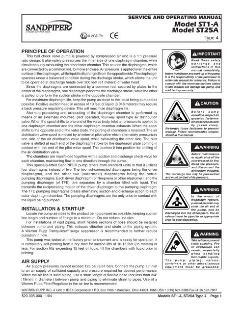
To re-install the sleeve and spool set, lightly lubricate the o-rings on the sleeve with ano-ring assembly lubricant or lightweight oil (such as 10 wt. air line lubricant). Press the setinto the valve body easily, without shearing the o-rings. Re-install one end cap, and retainingring on the valve body. Using the arbor press or bench vise that was used in disassembly,press the sleeve back into the valve body. Re-install the spool, keeping the counter-boredend toward you, and install the spring, opposite end cap and retaining ring on the valvebody. After inspecting and cleaning the gasket surfaces on the valve body and intermediate,re-install the valve body on the pump using new gaskets. Tighten the four hex head capscrewsevenly and in an alternating cross pattern, at 150 in./lbs. (16.94 Newton meters).PILOT VALVEThe pilot valve assembly is accessed by removing the main air distribution valve body fromthe pump and lifting the pilot valve body out of the intermediate housing (see Figure 8).Most problems with the pilot valve can be corrected by replacing the o-rings. Alwaysgrease the spool prior to inserting it into the sleeve. If the sleeve is removed fromthe body, reinsertion must be at the chamfered side. Grease the o-rings to slide thesleeve into the valve body. Securely insert the retaining ring around the sleeve. Whenreinserting the pilot valve, push both plungers (located inside the intermediate bracket)out of the path of the pilot valve spool ends to avoid damage.PILOT VALVE ACTUATORBushings for the pilot valve actuators are held in the inner chambers wthretaining rings. An o-ring is behind each bushing. If the plunger has any sidewaysmotion check o-rings and bushings for deterioration/wear. The plunger may be removed forinspection or replacement. First remove the air distribution valve body and the pilot valvebody from the pump. The plungers can be located by looking into the intermediate. It maybe necessary to use a fine piece of wire to pull them out. The bushing can be removedfrom the inner chamber by removing the outer chamber assembly. Replace the bushingsif pins have bent (see Figure 9 and Figure 10).filling of driver chamber with liquidThe driver chambers are filled at the factory with distilled water.If you need to substitute another liquid to prevent system contamination, first consultthe factory for chemical compatibility with pump construction.Follow the steps listed below to replace the liquid in the pump after disassembly orliquid loss:1. Filling is accomplished through the pipe plugs at the top of the liquid chamber.Drain ports are at the bottom of the liquid chamber.2. After the driver fluid has been emptied from the pump, the driver diaphragms willnaturally come to center.3. Remove the entire manifold assembly exposing the ports in the outer diaphragmchambers.4. Fill either side with 722 MI. or 24.6 fluid oz. by volume with the driver liquid. It isimperative that the driver liquid chambers be filled with the correct amount of driver liquidas too little or too much will cause premature diaphragm failure and erratic pumping.5. After filling with the proper amount of liquid, if the liquid does not come to the topof the fill hole, pressure should be applied to the PTFE diaphragm with a blunt toolthrough the material flow port in the outer chamber until the liquid comes to the top. Ifthe main air valve body and pilot valve are removed, the diaphragm rod will be visible inthe intermediate bracket. The hole in the diaphragm rod will assist manual movement.Use a long taper punch to move the diaphragm rod.6. When the driver fluid rises to the top of the fill plug hole, apply pipe dope to the pipeplug, and thread it into the chamber plug hole. (Do not use PTFE tape.) Keep pressureon the PTFE diaphragm until the pipe plug is tight to prevent air from drawing back intothe chamber.7. Repeat the filling procedure for opposite side.TROUBLESHOOTING1. Pump will not cycleA. Check to make sure the unit has enough pressure to operate and that the air inletvalve is open.B. Check the discharge line to insure that the discharge line is neither closed norblocked.520-005-000 1/04 <strong>Model</strong>s <strong>ST1</strong>-A, <strong>ST25A</strong> Type 4 Page 5
C. If the spool in the air distribution valve is not shifting, check the main spool. It mustslide freely.D. Excessive air leakage in the pump can prevent cycling. This condition will be evident. Airleakage into the discharge line indicates a ruptured diaphragm. Air leakage from the exhaustport indicates leakage in the air distribution valve. See further service instructions.E. Blockage in the liquid chamber can impede movement of diaphragm.2. Pump cycles but will not pumpA. Suction side of pump pulling in air. Check the suction line for air leaks and be surethat the end of the suction line is submerged. Check flange bolting. Check valve flangesand manifold to chamber flange joints.B. Make certain the suction line or strainer is not plugged. Restriction at the suction isindicated by a high vacuum reading when a vacuum gauge is installed in the suctionline.C. Check valves may not be seating properly. To check, remove the suction line andcover the suction port with your hand. If the unit does not pull a good suction (vacuum),the check valves should be inspected for proper seating.D. Static suction lift may be too high. Priming can be improved by elevating the suctionand discharge lines higher than the check valves and pouring liquid into the unit throughthe suction inlet. When priming at high suction lifts or with long suction lines operate thepump at maximum cycle rate.E. <strong>Inc</strong>orrect driver fluid level or unpurged air in the chamber can cause poorperformance.3. Low performanceA. Capacity is reduced as the discharge pressure increases, as indicated on theperformance curve. Performance capability varies with available inlet air supply. Checkair pressure at the pump inlet when the pump is operating to make certain that adequateair supply is maintained.B. Check vacuum at the pump suction. Capacity is reduced as vacuum increases.Reduced flow rate due to starved suction will be evident when cycle rate can be variedwithout change in capacity. This condition will be more prevalent when pumping viscousliquids. When pumping thick, heavy materials the suction line must be kept as large indiameter and as short as possible, to keep suction loss minimal.C. Low flow rate and slow cycling rate indicate restricted flow through the discharge line.Low flow rate and fast cycling rate indicate restriction in the suction line or air leakageinto suction.D. Unstable cycling indicates improper check valve seating on one chamber. Thiscondition is confirmed when unstable cycling repeats consistently on alternate exhausts.Cycling that is not consistently unstable may indicate partial exhaust restriction dueto freezing and thawing of exhaust air. Use of an anti-freeze lubricant in an air linelubricator should solve this problem.E. <strong>Inc</strong>orrect driver fluid level or unpurged air in the chamber can cause poorperformance.For additional information, see the Warren Rupp Troubleshooting Guide.WARRANTYThis pump is warranted for a period of five years against defective material andworkmanship. Failure to comply with the recommendations stated in this manual voidsall factory warranty.RECOMMENDED WARREN RUPP ACCESSORIES TOMAXIMIZE PUMP PERFORMANCE:• Tranquilizer ® Surge Suppressor: For nearly pulse-free flow.• Warren Rupp ® Filter/Regulator: For modular installation and serviceconvenience.• Warren Rupp Speed Control: For manual or programmable processcontrol. (Manual adjustment or 4-20mA reception.)For more detailed information on these accessories, contact your localWarren Rupp Factory-Authorized Distributor, or Warren Rupp corporateheadquarters.520-005-000 1/04 <strong>Model</strong>s <strong>ST1</strong>-A, <strong>ST25A</strong> Type 4 Page 6
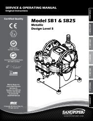
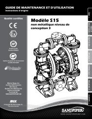
Grounding The PumpWARNINGTake action to prevent static sparking.Fire or explosion can result, especiallywhen handling flammable liquids. Thepump, piping, valves, containers orother miscellaneous equipment mustbe grounded.One eyelet is installed to a true earth ground.One eyelet is fastened to the pump hardware.This 8 foot long (244 centimeters) GroundStrap, part number 920-025-000 can beordered as a service item.To reduce the risk of static electrical sparking, this pump must be grounded.Check the local electrical code for detailed grounding instruction and thetype of equipment required, or in the absence of local codes, an industry ornationally recognized code having juristiction over specific installations.520-005-000 1/04 <strong>Model</strong>s <strong>ST1</strong>-A, <strong>ST25A</strong> Type 4 Page 7
II 2GD T5CESERVICE AND OPERATING MANUAL<strong>Model</strong> <strong>ST1</strong>-A<strong>Model</strong> <strong>ST25A</strong>Type 4ITEMNO. PART NO. DESCRIPTion qTY.2 165-042-157 Cap, Valve Body 13 170-063-115 Capscrew, Hex Head 14 901-035-115 Washer, Flat 75 542-001-115 Nut, Square 16 170-033-115 Capscrew, Hex Head 47 901-005-115 Washer, Flat 48 360-058-360 Gasket, Valve Cap 19 095-051-558 Body, Spool Valve 110 031-083-000 Sleeve & Spool Set w/Pins 111 165-078-147 Cap, End 212 675-043-115 Ring, Retaining 213 560-058-360 O-Ring 814 530-036-000 Muffler 115 360-057-360 Gasket 116 095-074-000 Pilot Valve Body Assembly 1 116-A 095-071-551 Pilot Valve Body 116-B 755-025-000 Sleeve (with O-Ring) 116-C 560-033-360 O-Ring (Sleeve) 416-D 775-014-000 Spool (with O-Ring) 116-E 560-023-360 O-Ring (Spool) 416-F 675-037-080 Retaining Ring 117 360-056-379 Gasket 118 114-007-157 Bracket, Intermediate 119 560-040-360 O-Ring 220 675-040-360 Ring, Sealing 221 170-043-115 Capscrew, Hex Head 622 196-043-157 Chamber, Inner 123 196-042-157 Chamber, Inner 124 070-012-170 Bearing, Sleeve 225 720-010-375 Seal, U-Cup 226 560-001-379 O-Ring 227 135-034-506 Bushing 228 675-042-115 Ring, Retainer 229 620-007-114 Plunger, Actuator 230 685-039-120 Rod, Diaphragm 131 901-012-180 Washer, Sealing 232 132-019-360 Bumper, Diaphragm 233 612-022-330 Plate, Inner 234 286-008-365 Diaphragm 2286-008-363 Diaphragm 235 612-101-110 Plate, Outer 236 196-023-000 Chamber Assembly 237 360-039-365 Gasket, Diaphragm 2360-039-363 Gasket, Diaphragm 238 286-009-604 Diaphragm 238 286-009-604 Diaphragm 21Available in Kit Form. Order P/N 031-060-000 which includesitems 8, 15, 17, 29, 45.Repair Parts shown in bold face (darker)type are more likely to need replacement afterextended periods of normal use. The pump ownermay prefer to maintain a limited inventory of theseparts in his own stock to reduce repair downtimeto a minimum.IMPORTANT: When ordering repair partsalways furnish pump model number, serialnumber and type number.MATERIAL CODESThe Last 3 Digits of Part Number000...Assembly, sub-assembly;and some purchased items010...Cast Iron015...Ductile Iron025…Music Wire080...Carbon Steel, AISI B-1112100...Alloy 20110...Alloy Type 316 Stainless Steel112...Alloy “C”114...303 Stainless Steel115...301/302/304 Stainless Steel120...416 Stainless Steel (Wrought Martensitic)148...Hardcoat Anodized Aluminum150...6061-T6 Aluminum151...6063-T6 Aluminum154...Almag 35 Aluminum155 or 156...356-T6 Aluminum157...Die Cast Aluminum Alloy #380159...Anodized Aluminum162...Brass, Yellow, Screw Machine Stock170...Bronze, Bearing Type, Oil Impregnated180...Copper Alloy330...Plated Steel331...Chrome Plated Steel332...Electroless Nickel Plated335...Galvanized Steel356...Injection Molded Hytrel357...Rupplon (Urethane Rubber)358…E.P.D.M. (Food Grade)359…Polyurethane360...Buna-N Rubber. Color coded: RED363...Viton (Fluorel). Color coded: YELLOW364...E.P.D.M. Rubber. Color coded: BLUE365...Neoprene Rubber. Color coded: GREEN366...Food Grade Nitrile. Color coded: WHITE375...Fluorinated Nitrile379...Conductive Nitrile405...Cellulose Fibre408...Cork and Neoprene425...Compressed Fibre440...Vegetable Fibre500...Delrin 500501...Delrin 570520...Injection Molded PVDF, NaturalColor, Food Grade/USDA Acceptable541...Nylon, Glass Filled550...Polyethylene551...Polypropylene552…Unfilled Polypropylene555…PVC558...Conductive HDPE570…Rulon II580...Ryton590…Valox600...PTFE (virgin material) Tetrafluoroethylene (TFE)603...Blue Gylon604...PTFE, Diaphragm608...Conductive PTFE610…PTFE Encapsulated Silicon611...PTFE Encapsulated Viton632…Neoprene Rupplon633…Viton/PTFE634…E.P.D.M./PTFE636…White Nitrile/PTFEDelrin, Viton and Hytrel are registered tradenames ofE.I. DuPont.Gylon is a registered tradename of Garlock, <strong>Inc</strong>.Nylatron is a registered tradename of Polymer Corporation.Rulon II is a registered tradename of Dixion Industries Corp.Ryton is a registered tradename of Phillips Chemical Company.Valox is a registered tradename of General Electric Company.SandPIPER, Warren Rupp, Tranquilizer, Rupplon are registeredtradenames of Warren Rupp, <strong>Inc</strong>.520-005-000 1/04 <strong>Model</strong>s <strong>ST1</strong>-A, <strong>ST25A</strong> Type 4 Page 8
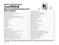
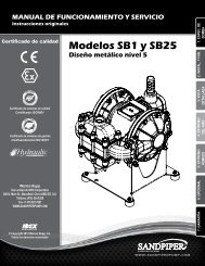
ITEMNO. PART NUMBER DESCRIPTion qTY.39 196-021-110 Chamber, Outer 2196-021-156 Chamber, Outer 240 170-029-115 Capscrew, Hex Head 1641 900-004-115 Washer, Lock 2642 545-004-115 Nut, Hex 4243 618-003-110 Pipe, Plug 844 115-071-080 Brk’t. Foot, Base 145 132-022-360 Bumper 246 350-002-360 Foot, Rubber 447 706-013-330 Screw, Machine 448 547-002-330 Nut, Stop 449 170-045-115 Capscrew, Hex Head 450 905-001-015 Washer, Taper 451 360-030-600 Gasket, Manifold 252 171-010-115 Capscrew, Flanged 453 170-047-332 Capscrew, Hex Head 654 334-013-157 Porting Flange 2334-013-110 Porting Flange 2334-013-157E Porting Flange (BSP) 2334-013-110E Porting Flange (BSP) 255 360-031-608 Gasket, Flange 456 050-011-600 Ball, Check Valve 457 722-047-110 Seat, Check Ball (Discharge) 258 518-020-110 Manifold 1518-020-156 Manifold 160 807-024-115 Stud 1661 618-003-330 Pipe Plug 365 286-015-604 Diaphragm, Overlay 266 132-028-552 Bumper, Spool 268 210-008-330 Clip, Safety 169 560-029-360 O-Ring 270 255-012-335 Coupling 3/4" NPT (Exhaust Port) 1ITEMS NOT SHOWN:031-111-558 Valve Body Assembly(<strong>Inc</strong>ludes items 9, 10,11, 12, 13, 66, 68 & 69) 1Repair Parts shown in bold face (darker)type are more likely to need replacementafter extended periods of normal use. Thepump owner may prefer to maintain a limitedinventory of these parts in his own stock toreduce repair downtime to a minimum.IMPORTANT: When ordering repair partsalways furnish pump model number, serialnumber and type number.MATERIAL CODESThe Last 3 Digits of Part Number000...Assembly, sub-assembly;and some purchased items010...Cast Iron015...Ductile Iron025…Music Wire080...Carbon Steel, AISI B-1112100...Alloy 20110...Alloy Type 316 Stainless Steel112...Alloy “C”114...303 Stainless Steel115...301/302/304 Stainless Steel120...416 Stainless Steel (Wrought Martensitic)148...Hardcoat Anodized Aluminum150...6061-T6 Aluminum151...6063-T6 Aluminum154...Almag 35 Aluminum155 or 156...356-T6 Aluminum157...Die Cast Aluminum Alloy #380159...Anodized Aluminum162...Brass, Yellow, Screw Machine Stock170...Bronze, Bearing Type, Oil Impregnated180...Copper Alloy330...Plated Steel331...Chrome Plated Steel332...Electroless Nickel Plated335...Galvanized Steel356...Injection Molded Hytrel357...Rupplon (Urethane Rubber)358…E.P.D.M. (Food Grade)359…Polyurethane360...Buna-N Rubber. Color coded: RED363...Viton (Fluorel). Color coded: YELLOW364...E.P.D.M. Rubber. Color coded: BLUE365...Neoprene Rubber. Color coded: GREEN366...Food Grade Nitrile. Color coded: WHITE375...Fluorinated Nitrile379...Conductive Nitrile405...Cellulose Fibre408...Cork and Neoprene425...Compressed Fibre440...Vegetable Fibre500...Delrin 500501...Delrin 570520...Injection Molded PVDF, NaturalColor, Food Grade/USDA Acceptable541...Nylon, Glass Filled550...Polyethylene551...Polypropylene552…Unfilled Polypropylene555…PVC558...Conductive HDPE570…Rulon II580...Ryton590…Valox600...PTFE (virgin material) Polytetrafluoroethylene(PTFE)603...Blue Gylon604...PTFE, Diaphragm608...Conductive PTFE610…PTFE Encapsulated Silicon611...PTFE Encapsulated Viton632…Neoprene Rupplon633…Viton/PTFE634…E.P.D.M./PTFE636…White Nitrile/PTFEDelrin, Viton and Hytrel are registered tradenames ofE.I. DuPont.Gylon is a registered tradename of Garlock, <strong>Inc</strong>.Nylatron is a registered tradename of PolymerCorporation.Rulon II is a registered tradename of Dixion IndustriesCorp.Ryton is a registered tradename of Phillips ChemicalCompany.Valox is a registered tradename of General ElectricCompany.SandPIPER, Warren Rupp, Tranquilizer, Rupplon areregistered tradenames of Warren Rupp, <strong>Inc</strong>.520-005-000 1/04 <strong>Model</strong>s <strong>ST1</strong>-A, <strong>ST25A</strong> Type 4 Page 9
NOTE: Usual installation for the outer chamber andmanifold is 180° from the view shown.12111013669696813OVERLAY UNITS©2004 Warren Rupp, <strong>Inc</strong>. All rights reserved.®SandPIPER, Warren Rupp, Tranquilizer are registered tradenames of Warren Rupp, <strong>Inc</strong>.®Neverseize is a registered tradename of Loctite.Printed in U.S.A.520-005-000 1/04 <strong>Model</strong>s <strong>ST1</strong>-A, <strong>ST25A</strong> Type 4 Page 10