CLASSIFICATION AND ZONING OF MARBLE SITES - HKU Libraries
CLASSIFICATION AND ZONING OF MARBLE SITES - HKU Libraries
CLASSIFICATION AND ZONING OF MARBLE SITES - HKU Libraries

Create successful ePaper yourself
Turn your PDF publications into a flip-book with our unique Google optimized e-Paper software.
<strong>CLASSIFICATION</strong> <strong>AND</strong><strong>ZONING</strong> <strong>OF</strong><strong>MARBLE</strong> <strong>SITES</strong>GEO REPORT No. 29Y.C. ChanThis report was originally produced in May 1989as GCO Technical Note No. TN 4/89
. 4 -FOREWORDThis report records the development of a system for thezoning and classification of marble sites. It describes thedetails of and the rationale behind the system. It hasapplications in the interpretation of karst morphology, planningof detailed ground investigation and design of foundations.The system was developed by Mr Y.C. Chan under thesupervision of Mr M.C. Tang. Mr W.K. Pun performed mostof the computation involved.The drafting services provided by Special ProjectsDivision is gratefully acknowledged.M.C. TangAg Chief Geotechnical Engineer/Mainland West
- 5 -CONTENTSTitle Page 1PREFACE 3FOREWORD 4CONTENTS 51. INTRODUCTION 72. AIM 73. CONSULTATION 74. KARST MORPHOLOGY 74.1 Factors Affecting Karst Dissolution 74.2 Hydrology of a Marble Rock Mass 84.3 Karst Features in Yuen Long 94.4 Effect of Dissolution on Rock Mass Quality 105. RQD <strong>AND</strong> DISSOLUTION 106. PARAMETERS FOR THE <strong>CLASSIFICATION</strong> SYSTEM 106.1 Basic Parameter 106.2 Defined Parameter 107. THE <strong>CLASSIFICATION</strong> SYSTEM 127.1 The MQD Values and Rock Mass Classes 127.2 Borehole Rating 127.3 Site Zoning and Classification 138. APPLICATION 148.1 Initial Ground Investigation 148.2 Design Guidelines 149. CASE EXAMPLES 1510. SUMMARY 15PageNo.
- 6 -11. POTENTIAL DEVELOPMENT 1512. REFERENCES 16LIST <strong>OF</strong> FIGURES 17APPENDIX A : <strong>CLASSIFICATION</strong> <strong>OF</strong> <strong>MARBLE</strong> SITE - SITE A 26APPENDIX B : <strong>CLASSIFICATION</strong> <strong>OF</strong> <strong>MARBLE</strong> SITE - SITE B 32PageNo.
- 7 -1. INTRODUCTIONIn January 1989, the Mainland West Division of the Geotechnical Control Officestarted a search for a system of classifying or zoning marble sites.- This report records thework done and the details of the proposed system as illustrated by case examples.2. AIMThe aim of the exercise is to develop a system of classifying or zoning marble sitesbased on borehole data to :(i)(ii)obtain an indication of the difficulty of designing andconstructing foundations.gain a better understanding of the geology.Regarding (i), there are two levels of engineering applications. The first level is toclassify sites from the preliminary stage ground investigation. The site classes should allowthe engineer to decide on the potential foundation problems and solutions and hence to plana good stage 2 ground investigation with a good idea of what to look for. The second levelis to assist interpretation of all ground investigation data to decide on a site class from whichthe engineer can draw precedent cases with regard to the choice of foundation types, foundinglevels and supervision requirement.By plotting the site classes on a geology map, we may be able to correlate site classeswith geology. This would in the future allow identification of potential difficult sites fromknown geology features and vice versa. This is however a secondary aim that may onlyrealise after data from sufficient number of sites are collected.3. CONSULTATIONThe Resident Consultant Geologist, Messrs Dames & Moore (HK) and Dr A.C.Meigh, all of them are GCO consultants serving on the marble study project, wereapproached for assistance. Dr A.C. Meigh provided a series of useful thoughts.In addition, the author is in debt to Dr R.L. Langford for his surface karst concept.4. KARST MORPHOLOGY4.1 Factors Affecting Karst DissolutionMarble or limestone is sparingly soluble in water with dissolved carbon dioxide. Thefollowing formula summarises the reaction involved.CaCO 3 + CO 2 + H 2 O ^ Ca* + + 2HCO 3 ~
For the dissolution of CaCO 3 to continue, there must be a continuous supply of carbondioxide and water.The supply of carbon dioxide to the part of water in touch with the limestone dependson a number of factors in a complicated manner e.g. pH value, temperature, partial pressureof CO 2 in the air adjacent to the water surface, mechanism of distribution of CO 2 fromair/water interface to the water/marble interface. In general, low temperature, high partialpressure and turbulance in the water would all encourage high CO 2 concentration at themarble/water interface.Whilst the CO 2 concentration can vary within a certain range, the amount of wateravailable to dissolve the calcitic rock mass can vary tremendously and is the main controllingfactor. It depends on the hydrology of the area, the location and the characteristics of therock mass.4.2 Hydrology of a Marble Rock MassWater travels in a marble rock mass mainly along joints and fractured zones. Thiswater flow would dissolve the joint walls hence widening the joints. As a result, thepermeability of a marble rock mass would increase with time. Likewise the contrast inpermeability within the rock mass would also increase with time hence exaggerating anyinitial difference in conditions.Figure 1 shows the different possible paths of water flow in a marble rock mass.Marble rock mass is relatively permeable. Part of the rainfall would infiltrate into therock and travel down along joints. The flow volume would depend on joint width andspacing. Hence, the flow is much larger in a fractured or fault zone.Depending on the rainfall intensity, some of the rainfall may collect on the marble assurface runoff and drain towards local depressions to form temporary ponds or swamps.Joints daylighting in or adjacent to the depression would have strong flow because of bettersupply of water.When two or more fractured zones intersect, a linear belt of very fractured rock willform. It would tend to collect water from the fractured zone to flow in a lateral direction.Rainfall on a non-marble rock would collect along surface streams. When suchstreams meet marble, water would infiltrate into the marble and move on as concentratedflows along the marble/non-marble interface as a result of low permeability of the latter.Likewise, when water conducting joints meet less permeable dykes, the water would collectto contribute a concentrated flow at the dyke interface.This flow pattern would in the end control the form and pattern of karst features in therock mass as explained below.
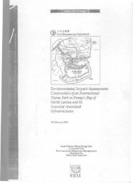
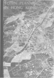
- 9 -4.3 Karst Features in Yuen LongThe following karst features have been interpreted from detailed ground investigationson building sites in Yuen Long. Their relations with the hydrology of the marble rock massare shown in Figure 2.(a)Surface KarstThis is at the rockhead where the marble rock mass is seriouslyweakened and dissected by dissolution channels. It is usually 5 mthick but may be up to 15 metres. The more developed surfacekarst are usually found at depressions where the continuous supplyof water was more effective in dissolving marble. The depressionsmight have been swampy in which case the higher partial pressureof carbon dioxide would increase the rate of dissolution drasticallyand contributed to a much more developed surface karst.(b)OverhangsThe solution channels might undercut the rock mass leaving a capof good quality marble on top. These are named as overhangs.(c)Dissolution JointsThese are joints locally opened by dissolution. The joint wallremains in contact at most locations. The effect of these affectedjoints on the rock mass strength is not significant.(d)Deep Cavity ZoneThis registers the location of concentrated water flow in thegeological past. It is usually in form of series of medium to smallsize cavities in a zone 10 m or more thick.(e)Underground ChannelsThis is found at points of concentrated flow along fractured rockmass where the many joints facilitated dissolution and collapse ofsmall cavities to form a few large cavities.(f)Underground CavityAt the marble/non-marble boundary, surface stream along the nonmarblewould direct concentrated flow into the rock interface. Thiswould encourage dissolution of the rock mass. If the flow velocityis sufficiently large, it would also erode the decomposed non-marblerock. Such erosion would leave a very large underground cavity.Features (c) to (f) arc regarded as deep karst features in the subsequent part of this
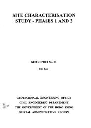
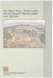
- 10 -report.4.4 Effect of Dissolution on Rock Mass QualityThe immediate effect of marble dissolution is a redistribution of stresses. The resultis fracturing of the rock mass as shown in Figure 3.The lost of insitu stresses at the surface karst zone and adjacent to the small cavitieswould cause the joints to open. The effect on rock mass quality is small. However, largeshear and tensile stresses would be induced in the vicinity of cavities of large extent and inthe pinnacles. This would cause the rock to fracture reducing the rock mass strength andrigidity.5. ROD <strong>AND</strong> DISSOLUTIONThe Rock Quality Designation (RQD) is an indirect measure of the fracture spacingin a rock mass. Since fractured rock is favourable to dissolution, low RQD values imply thepotential existence of cavities in the rock mass being examined. This is also true if thefractures are induced by karst features as explained in Section 4.4.From an engineering point of view, an underground cavity is important if there is amechanism for the adjacent rock mass to move into it under stress. RQD value is a goodmeasure of rock mass strength against such movement.6. PARAMETERS FOR THE <strong>CLASSIFICATION</strong> SYSTEM6.1 Basic ParameterThe Rock Quality Designation (RQD) value has been adopted as the basic parameterfor the classification system. In addition to the reasons given in Section 5, RQD also presentsthe advantage of being a relatively reliable parameter recorded in logs not prepared underclose supervision or with detailed description of dissolution features. It would therefore allowwider application of the classification system.6-2 Defined ParameterThe Marble Quality Designation (MQD) has been defined as :MQD = Average RQD x Marble Rock Recovery Ratio (MR)LI rlx 1Average RQD = ]T \L, \MR = ~ 1:(V L I}
- 11 -where lj is the length of core of RQD value rj.Lj is the top elevation of the section of core being considered.L 2 is the bottom elevation of the section of core being considered.Lj) is usually 5 m.Figure 4 illustrates the definition.It can be seen that the MQD is a combined measure of the effects of dissolution voidsand the physical and mechanical implications of fractures on a cavity affected rock mass.Furthermore, the rock masses can be classified according to the following range of MQDvalues.Marble Class MOD Values (%)75.1- 100II 50.1-75DescriptionVery good quality marble mass consisting ofrock with widely spaced fractures and unaffectedby dissolution.Good quality marble mass consisting of rockslightly affected by dissolution or slightlyfractured rock essentially unaffected bydissolution.IIIIV25.1 -5010.1-250- 10Fair quality marble mass consisting of fracturedrock or rock moderately affected by dissolution.Poor quality marble mass consisting of veryfractured rock or rock seriously affected bydissolution.Very poor quality marble mass consisting ofrock similar to class IV marble except thatcavities can be very large and marblecontinuous.In this system, Class I and II marble masses are definitely good for foundationpurpose. Class IV and V marble masses are definitely unsuitable. The implication of ClassIII rock would however require some elaboration.In one extreme, the Class III rating may purely be a result of rock joint spacings inwhich case the rock mass should be able to stand the usual range of foundation stresses (5MPa) unless it is close to other cavities;In another extreme, the Class III rating may be a result of large cavities in a widely
- 12 -jointed-rock. If the MQD is calculated for sections of 5 metres, the largest cavity that canbe found in one section of Class III rock is 2.5 m. This may not be critical to stability if thecavity is separated from the foundation by say 5 m of Grade I, II marble masses. If ClassIII marble exists in two consecutive sections, the largest possible cavity is 5 m. This wouldhave serious implications on foundation stability. Hence Class III is a marble mass ofmarginal rock quality and requires detailed examination of borehole records to assistinterpretation of its effect on the foundation design.7. The <strong>CLASSIFICATION</strong> SYSTEM7.1 The MOD Values and Rock Mass ClassesThe first step in the marble site classification system is to calculate MQD values forthe marble cores recovered from each borehole and assign the rock mass class for eachsection of the rock cores according to the method in Section 6.2. To facilitate subsequentapplication, the MQD values are best calculated for 5 m sections of the same reduced level,e.g. -40 mPD to »45 mPD, -45 mPD to -50 mPD and so on. The section location will bedesignated by the top reduced level of the section.At the rockhead, where the top section is shorter than the standard 5 m but longer than3 m, the average will be calculated for the exact length and designated as a full 5 m section.If the top section is shorter than 3 m, it will be grouped into the section immediately below.Figures 5 and 6 are some examples of this process.7.2 Borehole RatingTo facilitate identification of unfavorable karst features from the marble mass classes,the rock masses can be rated according to the following scheme.Rating(i) Surface karst 0(a zone of Class III, IV, V marblemass at rockhead).(ii) Overhang 5(5-10 m of Class I, II marble masscapping the surface karst).(iii) Class III marble separated by >5 m 10of I, II marble mass from thesurface karst.(iv) Class IV, V marble separated by >5 m 20of I, II marble from the surface karst.
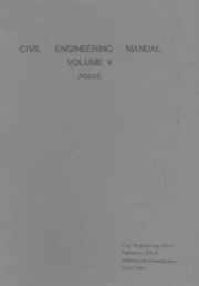
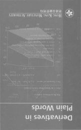
- 13 -The ratings are applied separately to all parts of the borehole logs. The sum of theratings becomes the borehole rating.Figure 7 illustrates the rating schedule.Boreholes with zero rating imply good quality rock and the ground in its vicinity isgood for foundation. A borehole rating of 5 implies some obstruction to piling to goodfoundation material. It can affect the building layout or piling method if this obstruction isextensive on plan. Boreholes of rating 10 to 15 imply potential foundation problems if it isadjacent to holes of higher rating. Borehole rating exceeding 15 would indicate difficultground condition requiring detailed ground investigation on the geology and trend of thecavity or cavity zones. Special designs are required to suit the building layout and groundconditions.7.3 Site Zoning and ClassificationIf the borehole rating and the base level of the surface karst is plotted on a plan, it ispossible to zone the site into areas of similar rating, as illustrated in Figures 8 and 9.Figure 8 shows a site where most of the holes are with zero rating. The bottom levelof the surface karst zone is at -35 to -45 mPD. A continous overhang caps the southern partof the site. In general, the site is easy to develop. However because of the possible lateralcontinuity of the overhang, its effect on foundation design and construction would needdetailed consideration.Figure 9 shows a site where most of the boreholes are again with a zero rating.However, at the east and west of the lower part of the site, there are 3 holes with ratinggreater than or equal to 10. In particular, hole DH18 shows 10 m of Grade III rock at adepth corresponding to the deep karst at DH20. DH19 is too short to reach this depth so thatit is very likely that the deep karst at DH18 and DH20 are connected. From the picture, itwould be advisable to avoid the southwestern corner of the site. Otherwise, the nature andextent of the deep karst at DH18 and DH20 should be examined in detail.Based on the percentage site area underlain by overhangs or deep karst, the sites canbe classified as follows.Percentage of area Site Descriptionwith borehole rating > 5 Class0-10 A Easy site10 - 25 B Fair site25-50 C Very Difficult site50-100 D Extremely Difficult siteHence, both sites at Figure 8 and 9 are classified as easy sites.
- 14 -For a large site, zones can be delineated to contain the minimum of obstructions,solution channels and deep karst features. These zones can be classified separately. Anexample is shown in Appendix B.8. APPLICATION8.1 Initial Ground InvestigationFor sites less than 1,000 m 2 in area, the initial ground investigation should consist ofat least 4 drillholes down to -80 mPD and located in a triangular grid. For sites in excessof 1,000 m 2 , the number of hole should be proportionally increased and be positioned in aregular grid pattern.The borehole ratings should be assigned according to Section 7.2. The percentage ofholes with borehole rating greater than zero should be calculated and compared with the siteclasses at Section 7.3 for an initial indication of the site condition. Initial zoning can also bedone on large sites at this stage to allow concentration of subsequent investigation efforts.In the subsequent investigation, boreholes should be sunk around those initialboreholes with rating greater than zero. The purpose of these holes is to trace the extent ofthe karst features (overhang, deep channels etc) being investigated. The investigation shouldbest be flexible and supervised by a geotechnical engineer or engineering geologist withexperience in karst morphology and foundation on karst marble. However, as a rough guide,holes may be sunk around the initial hole with high rating at a grid of 7 to 10m centres toa depth of approximately 20 m below the bottom of the karst feature being investigated.Boreholes in other parts of the site may be sunk along a grid or at points ofconcentration of piles to a depth of 20 m into rock.During the course of the detailed ground investigation, the drillhole cores and logsshould be continuously reviewed so that the investigation programme can be modified in timeto investigate new karst features intercepted.8.2 Design GuidelinesOn completion of all ground investigations, the site can be classified and zonedaccording to Section 7.3.For easy sites, driven H-piles of heavy sections would be the best foundation type.These piles can penetrate the surface karst easily. A nominal redundancy of 10-20% wouldbe adequate for the piles. The exact percentage redundancy depends on the thickness of thesurface karst as well as the nature and extent of the overhangs or deep karsts.Driven H-piles may still be most appropriate for fair sites. The percentageredundancy of the piles should be 20-30%. Bridging over or penetration of obstructions bypredrilling should be considered. It would also be appropriate to locate the building to avoidthe problem areas.
- 15 -No simple rules exist for very difficult and extremely difficult sites. The extent,nature and geological background of the problematic karst features must be known. The rockmass quality around these features should be assessed and a suitable foundation design canthen be attempted. This may be in form of deep bored piles to penetrate the zone, boredpiles underpinned by grouting or micropiles, micropiles alone, floating piles or floating raft.9. CASE EXAMPLESAppendix A illustrates the application of the classification system on a site in centralYuen Long. This is a site where piling has been completed. Appendix B is an applicationon a site in the eastern part of Yuen Long town. This case illustrates site zoning frompreliminary ground investigation results.10. SUMMARYA classification system for marble sites has been developed basing on some knowledgeof karst processes and common karst features in Yuen Long. The system utilises RQD as thebasic parameter. Five steps are involved in the application of the system.(a)(b)(c)(d)(e)Calculate the Marble Quality Designation (MQD) valuesfor sections of 5 metres according to the reduced levels.Assign the marble rock mass classes according to theMQD values.Calculate the borehole ratings according to the rockmass class patterns.Plot borehole ratings on plan to identify problem zones.Assign site classes according to the percentage area ofthe problem zone.Based on limited experience on design and construction of foundations on karst marblein the Yuen Long area, some tentative guidelines on ground investigation and foundationdesign have been associated with the site classes. This would be the immediate applicationof the classification system.11. POTENTIAL DEVELOPMENTWith some practice, engineers and geologists may use the borehole ratings to assistinterpretation of the karst morphology of the sites. This may turn out to be the real strengthof the system as illustrated by Chan & Pun (1994).As a follow up, this system will be applied to sites in the Designated Area with goodground investigation results. The system would then be reviewed for improvement.
- 16 -12. REFERENCESChan, Y.C. & Pun, W.K. (1994). The Method of Karst Morphology for Foundation Design(GEQ Report No. 32). Geotechnical Engineering Office, Hong Kong. (UnderPreparation).
- 17 -LIST <strong>OF</strong> FIGURESFigureNo.PageNo.1 Hydrology of a Marble Mass 182 Karst Features in Marble 193 Effect of Dissolution on Rock Mass Quality 204 Definition of Marble Quality Designation 205 Assignment of Marble Mass Classes Example 1 216 Assignment of Marble Mass Classes Example 2 227 Examples of Borehole Ratings 238 Site Zoning and Classification Example 1 249 Site Zoning and Classification Example 2 25
RAINFALLTemporary ponding /swamps at depressionSurface runoffNon-marblerock
Original groundsurface£ SurfacekarstNon- marblerockUndergroundchannelSmall linear cavitiesalong joints( dissolution joints }teep cavityzoneFigure 2 - Karst Features in Marble
- 20 -Insitustress-Joints[a)Before DissolutionShear and tensile stress zoneInsitu stress lost at surfacekarst zone and around smaltcavities(b)After DissolutionFigure 3 - Effect of Dissolution on Rock Mass QualityaDefine:Average RQD =LZ-LJMarble Rock Recovery Ratio (MR)where L£ - L j usually = 5mMQD = Average RQD x MRZero marble rockcore either cavity ordecomposednon-marble rock —(mPD)Figure 4 - Definition of Marble Quality Designation
- 21 --30M7892OOIT109.267.263.042.090.0205.0111.0145.0155.0118.6Jgfi.36.0TITXw o aa:1091176.4176.42394239.428U37U205.0316.0461.0155.0274.6274.62191289.63216o:SMinoaCOCN.**IIintoCMoX^»ro11inXp5toitinoXinCMCO8umm•la:-SO 1-55T"~TEllIZJT~TLZI171;EZI8694ooa:36.0132.3127.5125.625.8286763.727.045.027.015.00I—7-31.514.829.0018.0-36.01683J6O.295.842U27.953.7340.4449.663.790.790.7135.7135.7162.717t7'18A.7-31.531.5-SIS-BUS46346J75J75.3-93.3^933ooSoMinItt*»enC)totn*-.CMOxCNKCOiiinr^ovoX*°.CD*tlinox03IVLT>inroo XenCOenOfIIFigure 5'-. Assignment of Marble Mass Classes Example 1
- 22 -Figure 6 - Assignment of Marble Mass Classes Example 2
.ReducedLevelImPD)ClassBH1FeatureRatingClassBH2FeatureRatingClassBH3FeatureRating-20-25IOverhang5I-30VSurface karst0IIIV-35-40iiIIIImMarginal rockmass at depth10VIIISurface karst0-45iiiI-50iniiIto-55VI-60-65VVDeep karst20IIIIIIMarginal rockmass at depth10-70VI-75-80inIVDeep karst20E=25E = 10S = 30Figure 7 - Examples of Borehole Ratings
tBH1O BH4®BH2•40®BH3QBH5-35BH6Legend :i—Bottom level ofJ surface karst (m)^Location of holeBorehole ratingBorehole of less than15 m penetration intorockBH7 BH8 -35®BH9Site boundary-40
-35 ODHS®DH1-40 .35®DH2 DH6® -40-35 ®® DH3 O&H7 DH8A ®DH4 ®DH9N,20®DH12OHIO-30® DH 11Legend :/—Bottom level ofJr surf ace karst (m)V s —Location of hole\* —Borehole rating-30®DH13OBorehole of less than15 m penetration intorock"-25-— x/ _20 v®DH14-25^/@DH^8DH17® ^ B^rf *(0)DH16^j \ deepkaist @DH15! « |I ®DHlp«*— Site boundarytoUi\^®DH?0 QDH21O°H24-35 DH26®" 35 . 35-W DH23© DH27®1!Scale 1 : 250Figure 9 - Site Zoning and Classification Example 2
- 26 -APPENDIX A<strong>CLASSIFICATION</strong> <strong>OF</strong> <strong>MARBLE</strong> SITE - SITE A
- 27 -A.ISITE ATable Al lists the MQD values of all the boreholes. Figure Al shows the boreholeratings and the bottom levels of the surface karst.trend.Contouring of the bottom levels would highlight two depressions along a east westBetween the two depressions are boreholes of rating > 5. Close examination of theMQD values at Table Al would show that this represents a deep cavity zone connecting thetwo depressions. From the engineering point of view, the site is easy to develope but someattention would be required for the part of foundation above the deep cavity zone at themiddle-northern part of the site.
- 28 -LIST <strong>OF</strong> TABLESTableNo.PageNo.Al MQD Values and Marble Mass Classes for Site A 29
Table Al - MQD Values and Marble Mass Classes for Site ABoreholeBH1BH2BIBBH4BH5BH6BH7BH8BH9BH10BH11BH12BH13BH14BH15BH16BH17BH18BH19BH20BH21BH22BH23BH24BH25BH26BH27BH28BH29BH30BH31BH32BH33BH34BH35BH36BH37BH38BH39BH40-20 -2518.5953 96JO81,5 106822 2.4873 94j668JO 12555 100JOOjO 93.5QjQ51.155.1 35.1753 82312219,794.1 95295.4 97324315£ OjO733 SB70D 79.7232 504935 12JD78.7 25550.446.779.4275 63j610.4 74280JO 98JO89,7 95.467.7 100JO96.575-8233 97.569 JO752 90.46.5 90285.194 £-3090 &78 Q7.123100 JO100 Q88.565.57.176.183 JO94B36.495.597.196511.198371492 J66JO8526.473.587576.566582.583.1100 JO100 JO100 JO95383 JO-3516263*51JO100 JO97.178.089.772*85j627.4100 JO63240384393.140.68458JO70545S93 JO85585395.787.1100 JO100 JO-4088 JO93.448.196.175JO77J369 &20384S70 JO98.595j666338.763586384291588288.790694 j6100 JO100 JO0i) MQD ValuesSection Starting (mFD)-45 -50 -55 -60 -65 -7089.5100 JO93.4 813 86j594.7 100 JO93JO 983 98,0662 895 95,076.4 73.7 92,7 963 100JO91j6 54.4 84,8 913100 JO89 JO563 90 j6803 85.597554.595.4 98JO895 100 JO87.5 895 975 74JO90 JO94 JO100 JO-20IIIIIIVVIIII IIVIIIIIVIIIIIIVIIIIIVIVI-25IVIIVVIIVIIVIIIII IIIIVIIIVVVIIIIVIIIIIIII III IIIIIIIIII III-30IIVVIIIIIVIIIIII IIIIVIII IVVIIIIIIII-35IVII-40IIII IIIII IIII IIII IIIII IVIII IIII IIII IIIII III IIIV IIIIIII IIIIIII(b) Maible Mass Classes-45 -50 -55 -60 -65 -70III I III I III I III II I I II II I IIIIIIIIIIII II II I I IIIIIftoLegemdCodeIIIIIIIVMQD Raagp75.1 - 100%50.1 - 75%25.1 - 50 %10.1 - 25%
- 30 -LIST <strong>OF</strong> FIGURESFigureNo.No.Al Karst Morphology of Site A 31
- 31 -Borehole BH13Figure Al - Karst Morphology of Site A
- 32 -APPENDIX B<strong>CLASSIFICATION</strong> <strong>OF</strong> <strong>MARBLE</strong> SITE - SITE B
- 33 -B.ISITE BOnly the preliminary ground investigation has been completed on this site.Table Bl lists the MQD values of the boreholes.Figure Bl shows the borehole rating and the bottom levels of the surface karst.Due to widely spaced borehole information, the reconstruction of the karstmorphology is not possible. However, out of the 31 boreholes plotted,, 35% (11 holes) arewith rating > 5. The site would therefore be classified as "very difficult", implying the needfor very detailed ground investigation and probably building reorientation to avoid difficultground.A NE-SW line can however be drawn across the site. The lower half of the site iscavity free. The upper half of the site would have 55% of its holes (10 out of 18) withborehole rating > 5. This half of the site would be classified as "extremely difficult 11 withall its engineering implications.
- 34 -LIST <strong>OF</strong> TABLESTableNo.PageNo.Bl MQD Values and Marble Mass Classes for Site B 35
- 35 -Table Bl - MQD Values and Marble Mass Classes for Site B(a) MQD ValuesBorehole -20 -25BH1BH2BH3BH451.4BH5BH8768BH947.8BH1046.8BH11BH12BH1395.6BH14BH1636.0BH1795.7BH18BH19BH20BH21BH22BH23BH27BH28-3049.692.144.313.281.36.377.924.0-3596.99.589.480.423.475441.378.91.126.7 0.03.1 2.768.4 90.1100.0 100.048.614.987.898.411.529.231.092.094.188.178.6-40100.025.489.567.775.992.785.185.270.213.72.30.798.1100.016.281.380.985.753.30.8-4565.270.988.498.484.2100.0100.080.849.282.123.957.099.8100.074.01 60.093.261.591.2-5086.397.695.798.176.899.242.099.223.57.23.172.099.1100.098.580.951.475.941.384.4Section Starting (mPD)-55 -60 -65 -70 -75 -80 -85 -90 -9593.476.8100.096.794.581.4100.00.034.079.981.699.8100.02.897.4100.066.587.590.190.198.740.670.0100.0100.00.021.177.799.896.6100.00.048.692.674.288.6100.045.981.4100.0100.087.289.286.798.6100.03.332.993.085.3 98.581.045.6 88.7 100.0 100.077.496.2 98.2 826 950100.0 100.0 96.0 100.096.895.094.3100.081.4 89.4 87.4 100.047.8 13.00.0 573 66 3 64 6 78 1 76 433.2 39.4 45.1 8.793.3-10068.3(b) Marble Mass ClassesBorehole -20 -25BH1BH2BH3BH4IIBH5BH8IBH9IIIBH10IIIBHHBH12BH13IBH14BH16IIIBH17IBH18BH19BH20BH21BH22BH23BH27BH28-30SIIIIIVIvIIVIIITIIIIIISIIIV-35IVIIIVIIIISVTTIISIIIIIII-40IHIIIIIIIIIIIVTTIIIVIIIIIv-45IIII-50IIIIIVVvIIIIIIII III HIIIIIIIIVIIIIIIVVII-60Section Starting (mPD)-55 -65 -70 -75 -80 -85 -90 -95III III III III VII I I III II I IIIIIII I I IIII I I IIII I I III I I IIV VIII IV II IIII IIIIIIII I IV VIII IVI III V V II II IIII I-100IILegend :CodeIIIIIIIVVTSMQD Range75.1 - 100%50.1-75%25.1 - 50%10.1 - 25%0-10%Deco mposed non - marble rockNo n- marble rock
- 36 -LIST <strong>OF</strong> FIGURESFigureNo.PageNo.Bl Marble Site Zoning and Classification of Site B 37
-25jfflBH9BH16BH20BH27BH2^'Legend :-VolcanicBH7Non-marble rock-301-**'-30.40volcanic 4 cfyke°BH31@N-25 -* - Base level of surface karstfiH4 -*— Borehole referenceBorehole rating14Vokanlc&tfykeBH15BH19Volcanffi&sihstone° BH25Vokankj /J ./BH6Volcanico 1020 304050»QVcdonkBH7Figure Bl - Marble Site Zoning and Classification of Site B
GEOTECHNICAL ENGINEERING <strong>OF</strong>FICE PUBLICATIONSGeotechnical Manual for Slopes, 2nd edition (1984),306 p. (Reprinted, 1994).Guide to Retaining Wall Design, 2nd edition (1993),268 p. (Reprinted, 1994).Guide to Site Investigation (1987), 368 p. (Reprinted,1993).Guide to Rock and Soil Descriptions (1988), 195 p.(Reprinted, 1994).Guide to Cavern Engineering (1992), 159 p. (Reprinted,1994).Model Specification for Prestressed Ground Anchors, 2ndedition (1989), 168 p.Model Specification for Reinforced Fill Structures (1989),140 p.Mid-levels Study : Report on Geology, Hydrology andSoil Properties (1982), 265 p. plus 54 drgs.Prediction of Soil Suction for Slopes in Hong Kong, byM.G. Anderson (1984), 243 p.(Superseded by GCO Publication No. 1/85)(Superseded by Geospec 1)Review of Superficial Deposits and Weathering in HongKong, by J.D. Bennett (1984), 58 p. (Reprinted, 1993).Review of Hong Kong Stratigraphy, by J.D. Bennett(1984), 86 p.Review of Tectonic History, Structure and Metamorphismof Hong Kong, by J.D. Bennett (1984), 63 p.(Superseded by GCO Publication No. 1/88)Groundwater lowering by Horizontal Drains, by D.J.Craig & I. Gray (1985), 123 p. (Reprinted, 1990).Geoguide 1Geoguide 2Geoguide 3Geoguide 4Geospec 1Geospec 2GCO PublicationNo. 1/84GCO PublicationNo. 2/84GCO PublicationNo. 3/84GCO PublicationNo. 4/84GCO PublicationNo. 5/84GCO PublicationNo. 6/84GCO PublicationNo. 1/85GCO PublicationNo. 2/85HK$74(US$21.5)HK$48(US$16.5)HK$83(US$28)HK$58(US$18)HK$36(US$13.5)HK$25(US$5.5)HK$25(US$5.5)HK$200(US$34)HK$50(US$9)HK$40(US$8)HK$25(US$5.5)HK$20(US$5)HK$74(US$12)
(Superseded by GEO Report No. 9)Review of Design Methods for Excavations (1990), 193 p.(Reprinted, 1991).Foundation Properties of Marble and Other Rocks in theYuen Long - Tuen Mun Area (1990), 117 p.Review of Earthquake Data for the Hong Kong Region(1991), 115 p.Review of Granular and Geotextile Filters (1993), 141 p.Report on the Kwun Lung Lau Landslide of 23 July 1994,2 Volumes, 400 p. (Also available in Chinese)(Hong Kong) Rainfall and Landslides in 1984, byJ. Premchitt (1991), 91 p. plus 1 drg. (Reprinted, 1995).(Hong Kong) Rainfall and Landslides in 1985, byJ. Premchitt (1991), 108 p. plus 1 drg. (Reprinted, 1995).(Hong Kong) Rainfall and Landslides in 1986, byJ. Premchitt (1991), 113 p. plus 1 drg. (Reprinted, 1995).Hong Kong Rainfall and Landslides in 1987, byJ. Premchitt (1991), 101 p. plus 1 drg. (Reprinted, 1995).Hong Kong Rainfall and Landslides in 1988, byJ. Premchitt (1991), 64 p. plus 1 drg. (Reprinted, 1995).Hong Kong Rainfall and Landslides in 1989, by K.L. Siu(1991), 114 p. plus 1 drg. (Reprinted, 1995).Aggregate Properties of Some Hong Kong Rocks, by T. Y.Man, A. Cipullo, A.D. Burnett & J.M. Nash (1992),212 p. (Reprinted, 1995).Foundation Design of Caissons on Granitic and VolcanicRocks, by T.Y. Man & G.E. Powell (1991), 85 p.(Reprinted, 1995).Bibliography on the Geology and GeotechnicalEngineering of Hong Kong to December 1991, by E.W.Brand (1992), 186 p. (Superseded by GEO Report No.39)Bibliography on Settlements Caused by Tunnelling, byE.W. Brand (1992), 50 p. (Reprinted, 1995).GCO PublicationNo. 1/88GCO PublicationNo. 1/90GCO PublicationNo. 2/90GCO PublicationNo. 1/91GEO PublicationNo. 1/93GEO ReportNo. 1GEO ReportNo. 2GEO ReportNo. 3GEO ReportNo. 4GEO ReportNo. 5GEO ReportNo. 6GEO ReportNo. 7GEO ReportNo. 8GEO ReportNo. 9GEO ReportNo. 10HK$40(US$12)HK$58(US$10)HK$42(US$11.5)HK$32(US$19)FreeHK$118(US$17.5)HK$126(US$20)HK$126(US$20)HK$122(US$19.5)HK$106(US$16)HK$126(US$20)HK$120(US$19.5)HK$62(US$10.5)HK$48(US$8.5)
Direct Shear Testing of a Hong Kong Soil under VariousApplied Matric Suctions, by J.K. Can & D.G. Fredlund(1992), 241 p. (Reprinted, 1995).Rainstorm Runoff on Slopes, by J. Premchitt, T.S.K.Lam, J.M. ShenandH.F. Lam (1992), 211 p. (Reprinted,1995).Mineralogical Assessment of Creep-type Instability at TwoLandslip Sites, by T.Y. Man (1992), 136 p. (Reprinted,1995).Hong Kong Rainfall and Landslides in 1990, by K.Y.Tang (1992), 78 p. plus 1 drg. (Reprinted, 1995).Assessment of Stability of Slopes Subjected to BlastingVibration, by H.N. Wong & P.L.R. Pang (1992), 112 p.(Reprinted, 1995).Earthquake Resistance of Buildings and MarineReclamation Fills in Hong Kong, by W.K. Pun (1992),48 p. (Reprinted, 1995).Review of Dredging Practice in the Netherlands, by S.T.Gilbert & P.W. To (1992), 112 p. (Reprinted, 1995).Backfilled Mud Anchor Trials Feasibility Study, by C.K.Wong & C.B.B. Thorley (1992), 55 p. (Reprinted, 1995).A Review of the Phenomenon of Stress Rupture in HDPEGeogrids, by G.D. Small & J.H. Greenwood (1993),68 p. (Reprinted, 1995).Hong Kong Rainfall and Landslides in 1991, by N.C.Evans (1992), 76 p. plus 1 drg. (Reprinted, 1995).Horizontal Subgrade Reaction for Cantilevered RetainingWall Analysis, by W.K. Pun & P.L.R. Pang (1993),41 p. (Reprinted, 1995).Report on the Rainstorm of 8 May 1992, by N.C. Evans(1993), 109 p. plus 2 drgs. (Reprinted, 1995).Effect of the Coarse Fractions on the Shear Strength ofColluvium, by T.Y. Man & K.Y. Tang (1993), 223 p.(Reprinted, 1995).The Use of PFA in Reclamation, by J. Premchitt & N.C.Evans (1993), 59 p. (Reprinted, 1995).GEO ReportNo. 11GEO ReportNo. 12GEO ReportNo. 13GEO ReportNo. 14GEO ReportNo. 15GEO ReportNo. 16GEO ReportNo. 17GEO ReportNo. 18GEO ReportNo. 19GEO ReportNo. 20GEO ReportNo. 21GEO ReportNo. 22GEO ReportNo. 23GEO ReportNo. 24HK$136(US$21.5)HK$121(US$19.5)HK$87(US$15)HK$112(US$17)HK$75(US$12)HK$48(US$8.5)HK$76(US$12)HK$50(US$9)HK$56(US$9.5)HK$111(US$16.5)HK$44(US$8)HK$126(US$20)HK$126(US$20)HK$52(US$9)
Report on the Rainstorm of May 1982, by M.C. Tang(1993), 129 p. plus 1 drg. (Reprinted, 1995).Report on the Rainstorm of August 1982, by R.R. Hudson(1993), 93 p. plus 1 drg. (Reprinted, 1995).Landslips Caused by the June 1983 Rainstorm, by E.B.Choot (1993), 124 p. (Reprinted, 1995).Factors Affecting Sinkhole Formation, by Y.C. Chan(1994), 37 p. (Reprinted, 1995).Classification and Zoning of Marble Sites, by Y.C. Chan(1994), 37 p. (Reprinted, 1995).Hong Kong Seawall Design Study, by P.M. Aas &A. Engen (1993), 94 p. (Reprinted, 1995).Study of Old Masonry Retaining Walls in Hong Kong, byY.C. Chan (1995), under preparation.Karst Morphology for Foundation Design, by Y.C. Chan& W.K. Pun (1994), 90 p. plus 1 drg. (Reprinted, 1995).An Evaluation of the Suitability of Decomposed Granite asFoundation Backfill for Gravity Seawalls in Hong Kong,by E.B. Choot (1993), 34 p. (Reprinted, 1995).A Partial Factor Method for Reinforced Fill Slope Design,by H.N. Wong (1993), 55 p. (Reprinted, 1995).Hong Kong Rainfall and Landslides in 1992, by P.K.H.Chen (1993), 201 p. plus 2 drgs. (Reprinted, 1995).Methods of Test for Soils in Hong Kong for CivilEngineering Purposes (Phase I Tests), by P.Y.M. Chen(1994), 91 p.Creep, Stress Rupture and Hydrolysis of PolyesterReinforced Geogrids, by J.H. Greenwood (1995), underpreparation.Skin Friction on Piles at the New Public Works CentralLaboratory, by J. Premchitt, I. Gray & K.K.S. Ho(1994), 158 p. (Reprinted, 1995).Bibliography on the Geology and GeotechnicalEngineering of Hong Kong to May 1994, by E.W. Brand(1994), 202 p. (Reprinted, 1995).GEO ReportNo. 25GEO ReportNo. 26GEO ReportNo. 27GEO ReportNo. 28GEO ReportNo. 29GEO ReportNo. 30GEO ReportNo. 31GEO ReportNo. 32GEO ReportNo. 33GEO ReportNo. 34GEO ReportNo. 35GEO ReportNo. 36GEO ReportNo. 37GEO ReportNo. 38GEO ReportNo. 39HK$135(US$21)HK$118(US$17.5)HK$83(US$13)HK$40(US$7.5)HK$40(US$7.5)HK$68(US$11)HK$118(US$17.5)HK$38(US$7)HK$50(US$9)HK$167(US$25.5)HK$97(US$16.5)HK$118(US$19)
Hydraulic Fill Performance in Hong Kong, by C.K. Shen& K.M. Lee (1995), under preparation.Mineralogy and Fabric Characterization and Classificationof Weathered Granitic Rocks in Hong Kong, by T.Y.Man (1995), under preparation.Performance of Horizontal Drains in Hong Kong, by R.P.Martin, K.L. Siu & J. Premchitt (1995), underpreparation.Hong Kong Rainfall and Landslides in 1993, by W.L.Chan (1995), under preparation.General Report on Landslips on 5 November 1993 atMan-made Features in Lantau, by H.N. Wong & K.K.S.Ho (1995), under preparation.Gravity Retaining Walls Subject to Seismic Loading, byY.S. Au-Yeung & K.K.S. Ho (1995), under preparation.Direct Shear and Triaxial Testing of a Hong Kong Soilunder Saturated and Unsaturated Conditions, by J.K.M.Gan & D.G. Fredlund (1995), under preparation.Stability of Submarine Slopes, by N.C. Evans (1995),under preparation.Strength Development of High PFA Content Concrete, byW.C. Leung & W.L. Tse (1995), under preparation.AAR Potential of Volcanic Rocks from Anderson RoadQuarries, by W.C. Leung, W.L. Tse, C.S. Mok & S.T.Gilbert (1995), under preparation.Geotechnical Area Studies Programme - Hong Kong andKowloon (1987), 170 p. plus 4 maps.Geotechnical Area Studies Programme - Central NewTerritories (1987), 165 p. plus 4 maps.Geotechnical Area Studies Programme - West NewTerritories (1987), 155 p. plus 4 maps.Geotechnical Area Studies Programme - North West NewTerritories (1987), 120 p. plus 3 maps.Geotechnical Area Studies Programme - North NewTerritories (1988), 134 p. plus 3 maps.GEO ReportNo. 40GEO ReportNo. 41GEO ReportNo. 42GEO ReportNo. 43GEO ReportNo. 44GEO ReportNo. 45GEO ReportNo. 46GEO ReportNo. 47GEO ReportNo. 48GEO ReportNo. 49GASP IGASP IIGASP inGASP IVGASP VHK$240(US$40)HK$150(US$25)HK$150(US$25)HK$150(US$25)HK$150(US$25)
Geotechnical Area Studies Programme - North Lantau(1988), 124 p. plus 3 maps.Geotechnical Area Studies Programme - Clear Water Bay(1988), 144 p. plus 4 maps.Geotechnical Area Studies Programme - North East NewTerritories (1988), 144 p. plus 4 maps.Geotechnical Area Studies Programme - East NewTerritories (1988), 141 p. plus 4 maps.Geotechnical Area Studies Programme - Islands (1988),142 p. plus 4 maps.Geotechnical Area Studies Programme - South Lantau(1988), 148 p. plus 4 maps.Geotechnical Area Studies Programme - Territory of HongKong (1989), 346 p. plus 14 maps.Geology of Sha Tin, by R. Addison (1986), 85 p.Geology of Hong Kong Island and Kowloon, by P.J.Strange & R. Shaw (1986), 134 p.Geology of the Western New Territories, by R.L.Langford, K.W. Lai, R.S. Arthurton & R. Shaw (1989),140 p.Geology of Sai Kung and Clear Water Bay by P.J.Strange, R. Shaw & R. Addison (1990), 111 p.Geology of the North Eastern New Territories, underpreparation.Geology of Lantau, under preparation.Geology of Yuen Long by D.V. Frost (1992), 69 p.Geology of Chek Lap Kok by R.L. Langford (1994), 61p.GASP VIGASP VIIGASP VIIIGASP IXGASPXGASP XIGASP XIIGeologicalMemoir No. 1GeologicalMemoir No. 2GeologicalMemoir No. 3GeologicalMemoir No. 4GeologicalMemoir No. 5GeologicalMemoir No. 6Sheet ReportNo. 1Sheet ReportNo. 2HK$150(US$25)HK$150(US$25)HK$150(US$25)HK$150(US$25)HK$150(US$25)HK$150(US$25)HK$150(US$25)HK$50(US$9)HK$78(US$12.5)HK$97(US$17)HK$87(US$13)FreeFreeSan Tin : Solid and Superficial Geology (1:20 000 map) Map HGM 20,(1989), 1 map. Sheet 2HK$45
Sheung Shui : Solid and Superficial Geology (1:20 000map) (1992), 1 map.Kat O Chau : Solid and Superficial Geology (1:20 000map) (1993), 1 map.Tsing Shan (Castle Peak) : Solid and Superficial Geology(1:20 000 map) (1988), 1 map.Yuen Long : Solid and Superficial Geology (1:20000map) (1988), 1 map.Sha Tin : Solid and Superficial Geology (1:20 000 map)(1986), 1 map.Sai Kung Peninsula : Solid and Superficial Geology(1:20 000 map) (1989), 1 map.Tung Chung : Solid and Superficial Geology (1:20 000map) (1994), 1 map.Silver Mine Bay : Solid and Superficial Geology (1:20 000map) (1992), 1 map.Hong Kong and Kowloon : Solid and Superficial Geology(1:20 000 map) (1986), 1 map.Clear Water Bay : Solid and Superficial Geology(1:20 000 map) (1989), 1 map.Shek Pik : Solid and Superficial Geology (1:20 000 map),under preparation.Cheung Chau : Solid and Superficial Geology (1:20 000map), under preparation.Hong Kong South and Lamma Island : Solid andSuperficial Geology (1:20 000 map) (1987), 1 map.Waglan Island : Solid and Superficial Geology (1:20 000map) (1989), 1 map.San Tin : Solid Geology (1 : 20 000 map) (1994), 1 map.Lo Wu : Superficial Geology (1:5 000 map) (1990),1 map.Lo Wu : Solid Geology (1:5 000 map) (1990), 1 map.Map HGM 20,Sheet 3Map HGM 20,Sheet 4Map HGM 20,Sheet 5Map HGM 20,Sheet 6Map HGM 20,Sheet 7Map HGM 20,Sheet 8Map HGM 20,Sheet 9Map HGM 20,Sheet 10Map HGM 20,Sheet 11Map HGM 20,Sheet 12Map HGM 20,Sheet 13Map HGM 20,Sheet 14Map HGM 20,Sheet 15Map HGM 20,Sheet 16Map HGM20SMap HGP 5A,Sheet 2-NE-DMap HGP 5B,Sheet 2-NE-DHK$45HK$45HK$45HK$45HK$45HK$45HK$45HK$45HK$45HK$45HK$45HK$45HK$45HK$30HK$30
Mai Po : Superficial Geology (1:5 000 map) (1990), Map HOP 5A, HK$301 map. Sheet 2-SE-AMai Po : Solid Geology (1:5 000 map) (1990), 1 map. Map HOP 5B, HK$30Sheet 2-SE-ALok Ma Chau : Superficial Geology (1:5000 map) Map HGP 5A, HK$30(1990), 1 map. Sheet 2-SE-BLok Ma Chau : Solid Geology (1:5 000 map) (1990), Map HGP 5B, HK$301 map. Sheet 2-SE-BDeep Bay : Superficial Geology (1:5 000 map) (1989), Map HGP 5A, HK$301 map. Sheet 2-SW-CDeep Bay : Solid Geology (1:5 000 map) (1989), 1 map. Map HGP 5B, HK$30Sheet 2-SW-CShan Pui : Superficial Geology (1:5 000 map) (1989), Map HGP 5A, HK$301 map. Sheet 2-SW-DShan Pui : Solid Geology (1:5 000 map) (1989), 1 map. Map HGP 5B, HK$30Sheet 2-SW-DMan Kam To : Superficial Geology (1:5 000 map) (1990), Map HGP 5A, HK$301 map. Sheet 3-NW-CMan Kam To : Solid Geology (1:5.000 map) (1990), Map HGP 5B, HK$301 map. Sheet 3-NW-CTin Shui Wai: Superficial Geology (1:5 000 map) (1989), Map HGP 5A, HK$301 map. Sheet 6-NW-ATin Shui Wai : Solid Geology (1:5000 map) (1989), Map HGP 5B, HK$301 map. Sheet 6-NW-AYuen Long : Superficial Geology (1:5 000 map) (1989), Map HGP 5A, HK$301 map. Sheet 6-NW-BYuen Long : Solid Geology (1:5 000 map) (1989), 1 map. Map HGP 5B, HK$30Sheet 6-NW-BHung Shui Kiu : Superficial Geology (1:5 000 map) Map HGP 5A, HK$30(1989), 1 map. Sheet 6-NW-CHung Shui Kiu : Solid Geology (1:5 000 map) (1989), 1 Map HGP 5B, HK$30map.Sheet 6-NW-C
Muk Kiu Tau : Superficial Geology (1:5 000 map) (1990),1 map.Muk Kiu Tau : Solid Geology (1:5 000 map) (1990),1 map.Chek Lap Kok : Solid and Superficial Geology (1:5 000map) (1993), 1 map.Yam O Wan : Solid and Superficial Geology (1:5 000map) (1995), 1 map.Siu Ho : Solid and Superficial Geology (1:5 000 map)(1994), 1 map.Ma Wan : Solid and Superficial Geology (1:5 000 map)(1994), 1 map.Tsing Yi : Solid & Superfical Geology (1:5 000 map)(1995), 1 map.Pa Tau Kwu : Solid and Superficial Geology (1:5 000map) (1994), 1 map.Map HGP 5A,Sheet 6-NW-DMap HGP 5B,Sheet 6-NW-DMap HGP 5,Sheet 9-NE-C/DMap HGP 5,Sheet 10-NW-BMap HGP 5,Sheet 10-NW-CMap HGP 5,Sheet 10-NE-AMap HGP 5,Sheet 10-NE-B/DMap HGP 5,Sheet 10-NE-CHK$30HK$30HK$30HK$30HK$30HK$30HK$30HK$30ORDERING INFORMATION IS GIVEN ON THE NEXT PAGE
Copies of GEO publications (except Sheet Reports, 1:5 000 maps and other reports which arefree of charge) may be ordered by writing to :Publications (Sales) Office,Information Services Department,28th Floor, Siu On Centre,188 Lockhart Road, Wan Chai,Hong Kong.The Information Services Department will issue an invoice upon receipt of a written order.In Hong Kong, publications may be directly purchased from :Government Publications Centre,Ground Floor, Low Block,Queens way Government Offices,66 Queens way,Hong Kong.Requests for copies of Geological Survey Sheet Reports and other reports which are free ofcharge should be directed to :Chief Geotechnical Engineer/Special Projects,Geotechnical Engineering Office,Civil Engineering Department,Civil Engineering Building,101 Princess Margaret Road,Homantin, Kowloon,Hong Kong.1:5 000 maps may be purchased fromMap Sales Centre,Survey & Mapping Office,Lands Department,14th Floor, Murray Building,Garden Road,Hong Kong.All prices given in this List are for information only and may be changed without notice.The US$ prices shown are for overseas orders and are inclusive of surface postage toanywhere in the world. An additional bank charge of HK$50 or US$6.50 is required percheque made in currencies other than Hong Kong dollars. Cheques, bank drafts or moneyorders must be made payable to HONG KONG GOVERNMENT.
This book is due for return or renewal on the date shownunless previously recalled. Fines may be incurred for iatereturn.DATE DUEM' * * C.I M*."* >C^T
XDtDS7113LB 551,447 C45Chan, Y. C.Classification and zoning ofmarble sitesHong Kong : GeotechnicalEngineering Office, CivilEngineering Department; 1994.
Reprography by the Government Printer, Hong Kong 259857—6L—8/95 HK$40~~P58760029EOPrinted on paper made from woodpulp derived from renewable forestsUS$7.5 ISBN:962—02—0185—X