Oil Free Centrifugal Chiller with Magnetic Bearings - McQuay
Oil Free Centrifugal Chiller with Magnetic Bearings - McQuay
Oil Free Centrifugal Chiller with Magnetic Bearings - McQuay
- No tags were found...

Create successful ePaper yourself
Turn your PDF publications into a flip-book with our unique Google optimized e-Paper software.
Product ManualKPMWC00905-10ENDate: May 2010Supersedes:--<strong>Oil</strong> <strong>Free</strong> <strong>Centrifugal</strong> <strong>Chiller</strong><strong>with</strong> <strong>Magnetic</strong> <strong>Bearings</strong>WMCXE (High Efficiency) 100S ÷ 300DCooling Capacity from 317 to 1048 kWRefrigerant: R-134a<strong>McQuay</strong> is participating in the Eurovent Certification Programme.Product are as listed in the Eurovent Directory of Certified Productsand on the web site www.eurovent-certification.com
IndexFeatures and advantages ................................................................................................................................................. 3Next Generation <strong>Centrifugal</strong> ........................................................................................................................................... 3Benefit Summary............................................................................................................................................................ 3Code requirements – Safety and observant of laws/directives ....................................................................................... 3Certifications................................................................................................................................................................... 3Versions ......................................................................................................................................................................... 4Noise Configuration ........................................................................................................................................................ 4General characteristics..................................................................................................................................................... 5Cabinet and structure ..................................................................................................................................................... 5Frictionless <strong>Centrifugal</strong> compressor <strong>with</strong> magnetic bearings.......................................................................................... 5Ecological HFC 134a refrigerant..................................................................................................................................... 8Evaporator...................................................................................................................................................................... 8Condenser...................................................................................................................................................................... 8Electronic expansion valve ............................................................................................................................................. 8Refrigerant Circuit........................................................................................................................................................... 8Electrical control panel ................................................................................................................................................... 8Controller features and benefits ................................................................................................................................... 10Connection to BMS....................................................................................................................................................... 11Standard accessories (supplied on basic unit) ............................................................................................................. 11Options (on request)..................................................................................................................................................... 11Nomenclature .................................................................................................................................................................. 13Specifications WMC XE-ST ............................................................................................................................................ 14Sound Levels................................................................................................................................................................... 15Operating limits............................................................................................................................................................... 16Dimensions WMC XE-ST ................................................................................................................................................ 17Installation notes............................................................................................................................................................. 19Warning ........................................................................................................................................................................ 19Handling ....................................................................................................................................................................... 19Location........................................................................................................................................................................ 19Space requirements ..................................................................................................................................................... 20Technical Specification for <strong>Oil</strong> <strong>Free</strong> <strong>Centrifugal</strong> Water Cooled <strong>Chiller</strong> ...................................................................... 21GENERAL .................................................................................................................................................................... 21REFRIGERANT............................................................................................................................................................ 21PERFORMANCE.......................................................................................................................................................... 21UNIT DESCRIPTION.................................................................................................................................................... 21NOISE LEVEL AND VIBRATIONS............................................................................................................................... 21DIMENSIONS............................................................................................................................................................... 21CHILLER COMPONENTS............................................................................................................................................ 22KPMWC00905-10EN - page 2/24
Features and advantagesNext Generation <strong>Centrifugal</strong>The industry’s next generation of centrifugal chillers is here today <strong>with</strong> WMC chillers. The new technology begins <strong>with</strong>centrifugal compressors utilizing frictionless magnetic bearings for oil-free operation, integral variable-frequency drives,and high-speed direct drive technology. The high efficiency compressor is matched <strong>with</strong> highly efficient heat exchangersto make an impressive chiller. The control system is based on MicroTech II® family to provide the optimum chiller controlsystem.Benefit Summary- Breakthrough energy efficiency, especially at part load conditions, resulting in great energy savings.- Increased reliability This frictionless magnetic bearing design needs no oil management system, resulting inincreased reliability and reduced maintenance. With no oil to coat the heat transfer surfaces, a gain in heatexchanger efficiency can also be realized.- Compact design and light weight The compressor weight of 120 kg is less than 20% of the weight ofcompetitive compressors and approximately 50% smaller, this allows a compact unit design thus making thisseries the perfect choice for retrofit projects- Low noise level The WMC chiller is one of the quietest in its size range: this eliminates the need for expensivesound attenuation accessories and makes the unit ideal for every sound sensitive environments such as schools,performance halls, museums, etc.- Extremely low vibration levels As a result of the high-speed design, the compressor vibration levels areextremely low, minimizing vibration that could be transmitted to the structure.- Smart refrigerant choice The compressor is optimized for HFC 134a, the positive pressure refrigerant <strong>with</strong> nophase-out schedule and no ozone depletion.- Smart controls Onboard digital electronics provide smart controls. The compressor is totally self-correction andincorporates a system of sophisticated self-diagnostics, monitoring and controls.In the event of a power failure, the compressor motor acts as a generator, providing power for the bearing controlsystem during coast down. It also has a system to gently de-levitate the shaft.- Easy integration <strong>with</strong> BMS The unit controller can be connected to BMS (Building Management System) basedon the most common protocols as LONWORKS®, BACnet®, or Modbus®- Extensive option list A wide portfolio of options is available to meet different requirementsCode requirements – Safety and observant of laws/directivesAll WMC units are designed and manufactured in accordance <strong>with</strong> applicable selections of the following:Construction of pressure vessel 97/23/EC (PED)Machinery Directive2006/42/ECLow Voltage2006/95/ECElectromagnetic Compatibility2004/108/ECElectrical & Safety codes EN 60204–1 / EN 60335-2-40Manufacturing Quality Stds UNI – EN ISO 9001:2004CertificationsAll units manufactured are CE marked, complying <strong>with</strong> European directives in force, concerning manufacturing andsafety. On request units can be produced complying <strong>with</strong> laws in force in non European countries (ASME, GOST, etc.),and <strong>with</strong> other applications, such as naval (RINA, etc.).KPMWC00905-10EN - page 3/24
VersionsWMC is available in high efficiency version:XE: High Efficiency6 sizes to cover a range from 317 up to 1048 kW (Cooling Capacity), <strong>with</strong> EER up to 6.00 andESEER up to 9.60.The EER (Energy Efficiency Ratio) is the ratio of the Cooling Capacity to the Power Input of theunit. The Power Input includes: the power input for operation of the compressor, the power inputof all control and safety devices.The ESEER (European Seasonal Energy Efficiency Ratio) is a weighed formula enabling to takeinto account the variation of EER <strong>with</strong> the load rate and the variation of water inlet condensertemperature.ESEER = A x EER 100% + B x EER 75% + C x EER 50% + D x EER 25%A B C DCoefficient 0.03 (3%) 0.33 (33%) 0.41 (41%) 0.23 (23%)Condenser water inlet temperature (°C) 30 26 22 18Noise ConfigurationWMC is available in standard noise level configuration:ST: Standard NoiseKPMWC00905-10EN - page 4/24
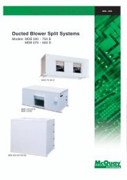
General characteristicsCabinet and structureThe cabinet is made of galvanized steel sheet and painted to provide a high resistance to corrosion. Colour Ivory White(Munsell code 5Y7.5/1) (±RAL7044).Frictionless <strong>Centrifugal</strong> compressor <strong>with</strong> magnetic bearingsThe frictionless <strong>Centrifugal</strong> compressor <strong>with</strong> magnetic bearings and integrated VFD is an innovative compressor thatallows great unit efficiency and reliability.The compressor’s one moving part (rotor shaft and impellers) is directly put in rotation by the permanent magnet directdrive motor and kept levitated by a digitally controlled magnetic bearing system; the speed of rotation reduces as thecondensing temperature and/or cooling load reduces. Movable inlet guide vanes, activated by step motor, redirect gasflow into the first stage impeller during low loads, after the compressor has reached minimum speed.Inverter speedcontrol2 stage centrifugalcompressorPressure andtemperature sensorsPermanent MagnetDirect Drive MotorInlet GuideVanesMotor andbearing control(the electronics)Fig.1MotorVariable Speed Permanent Magnet Direct Drive Motor (Fig.2), also known as ‘brushless’, is a synchronous motor,refrigerant cooled and fully protected <strong>with</strong> thermistors.Permanent magnets (Fig.3), placed onto the rotor, generate the magnetic flux that is necessary to provide torque.VFD (Variable Frequency Drive) is required to adjust, depending on the load, the speed of rotation that normally isbetween 18,000 and 48,000rpm.Fig.2Fig.3KPMWC00905-10EN - page 5/24
<strong>Magnetic</strong> bearing systemFig.4Fig.5Fig.61. The rotor shaft’s position is held by front and rear electro-magnetic cushions;2. The shafts position is monitored <strong>with</strong> 10 sensors that send a signal to a digital controller which then sends acommand to the 5 separate pulse width modulators (PWM), for a proper shaft repositioning;3. In case of power failure, <strong>with</strong>in 0.5 micro-seconds, the motor acts as a generator for the magnetic bearings andthe compressor comes gradually to a complete stop; the rotor de-levitates normally unto backup bearings.Onboard capacitors have enough power to fully support the bearing system during the coast down.The friction losses and the oil management hardware and controls associated <strong>with</strong> conventional oil-lubricated bearingsare now totally eliminated.There is no need for oil pumps, oil reservoirs, controls, starter, piping, heaters, oil coolers, oil filters, water regulatingvalves or oil relief valves that are needed to maintain oil quality. These devices can be a source of problems in traditionalchillers, and removing them significantly increases unit reliability and reduces the maintenance.Modern magnetic bearing technology along <strong>with</strong> the integrated VFD (variable-speed drive) enables outstanding energyefficiency, especially at partial loads, where significant gains can be realized.The improvements in terms of efficiency and annual energy cost is maximised when there are long periods of part loadoperation.Also the inrush current is strongly reduced thanks to the use of VFD, resulting in an advantageous down-sizing ofelectrical protection devices.KPMWC00905-10EN - page 6/24
ElectronicsInbuilt sophisticated electronics (Fig.7 and 8) guarantee self-diagnostics on Motor, bearings, compressor, expansionvalve, performance, events, faults,…and allow the exchange and visibility of data <strong>with</strong> the chiller controller.VFDShaft positioncontrol<strong>Magnetic</strong>bearing PWMFig. 7Line reactorRectifierDC-link capacitorsIGBTMotorSupply3 Phases380-480V50-60HZControllerCompressor controllerDC-DC converterPWM outputPower - MotorPower - GeneratorControl<strong>Magnetic</strong>bearingsFig. 8KPMWC00905-10EN - page 7/24
Ecological HFC 134a refrigerantThe compressors have been designed to operate <strong>with</strong> R-134a, ecological refrigerant <strong>with</strong> zero ODP (Ozone DepletionPotential) and very low GWP (Global Warming Potential) that means low TEWI (Total Equivalent Warming Impact).EvaporatorFlooded shell-and-tube evaporator operating <strong>with</strong> refrigerant in shell and water in tubes. Replaceable water tubes arefabricated from integral finned copper and mechanically bonded to steel tube sheets. The evaporator is PED designed,constructed, inspected and stamped. Water side working pressure is designed for 10,5 bar. Vessels include 1” NPTspring loaded pressure relief valves. Shell and non-connection water heads are insulated <strong>with</strong> 3/4” thick closed cellinsulation. Standard configuration on water connection side is 2 passes. The evaporator water outlet connections areprovided <strong>with</strong> Victaulic Kit (as standard).CondenserFlooded Shell-and-tube type operating <strong>with</strong> refrigerant in shell and water in tubes. Replaceable water tubes arefabricated from integral finned copper and mechanically bonded to steel tube sheets. Condenser is designed to conformPED. Water side working pressure is designed for 10.5 bar. Standard configuration on water connections side is 2passes. The condenser water outlet connections are provided <strong>with</strong> Victaulic Kit (as standard).Electronic expansion valveThe unit is equipped <strong>with</strong> the most advanced electronic expansion valves to achieve precise control of refrigerant massflow. As today’s system requires improved energy efficiency, tighter temperature control, wider range of operatingconditions, the application of electronic expansion valves becomes mandatory. Electronic expansion valves possessunique features: short opening and closing time, high resolution, positive shut-off function to eliminate use of additionalsolenoid valve, continuous modulation of mass flow <strong>with</strong>out stress in the refrigerant circuit and corrosion resistancestainless steel body.Electronic Expansion Valves are typically working <strong>with</strong> lower ΔP between high and low pressure side, than a thermostaticexpansion valve. The electronic expansion valve allows the system to work <strong>with</strong> <strong>with</strong>in a wide operating range <strong>with</strong>outany refrigerant flow problems and <strong>with</strong> perfect chilled water leaving temperature control.Refrigerant CircuitEach unit has 1 refrigerant circuit including:• 1 or 2 Compressors• Electronic expansion valve• Evaporator• 1 or 2 ( 1/compressor) safety valve on suction side• Manometers on evaporator and condenser• Condenser• Safety valves on evaporator and condenser• Water pressure differential switch on evaporator and condenserElectrical control panelPower and control are located in two sections of the main panel that is manufactured to ensure protection against allweather conditions. The electrical panel is IP54 and (when opening the doors) internally protected <strong>with</strong> Plexiglas panelagainst possible accidental contact <strong>with</strong> electrical components (IP20). The main panel is fitted <strong>with</strong> a main switchinterlocked door.Power SectionThe power section includes circuit breaker, compressors inverters, control circuit transformer.KPMWC00905-10EN - page 8/24
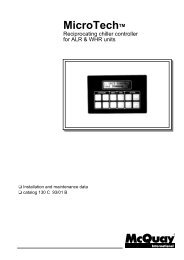
MicroTech II controllerThe control system of the chiller consists of two major components: the operator interface panel and the unit controlpanel.The touch screen panel is on an adjustable arm so that it can bepositioned comfortably for the operator.The operator interface panel has a Super VGA touch-screen, utilizinggraphics to provide clear and concise information on the chiller status,alarms, trends, and setpoint adjustment. Should the touch-screenbecome inoperable, the unit and compressor controllers will continueuninterrupted operation of the chiller.Fig.8The control panel contains a USB port for downloading the unit’s fault history, major parameter trends, and the unitoperating manual that is stored in the microprocessor. These design features built into this control system optimize easeof operation, reliability, and efficient operation.The unit’s control panel is featured <strong>with</strong> the controller, which is responsible for functions involving the single compressorsand the entire unit (controlling the electronic expansion valve, for instance) and is the interface point for devices andsignals external to the unit.EXV BoardField Wiring Knockouts EXV BoardOn/OffSwitchesUNITCOMP #1COMP #2Terminal Board TB UTB1 For FieldWiring Connections Field WiringKnockouts EXV BoardControllerOITS PCUniversalCommunication ModuleComp #1 I/OComp #2 I/OFig. 9KPMWC00905-10EN - page 9/24
Controller features and benefitsFEATUREEasy integration into Building Management SystemEasy to read, adjustable, Super VGA colour touchscreen operator interfaceHistoric trend data-downloadablePrecise ± 0.2 °F chilled water controlProactive pre-shutdown correction of “unusualconditions” allows chiller to stay liAutomatic control of chilled water and condenserwater pumpsControls up to four stages of tower fans andmodulation of tower fan and/or bypass valveTwenty-five previous alarm descriptions are stored inmemoryOperating and maintenance manuals plus unit partslists stored in memoryMultiple language capabilityBENEFITDesigner can select any BAS supplier using standardopen protocols and know the MicroTech II control willinterface <strong>with</strong> it.Operators can observe chiller operation at a glance andeasily select various data screens and change setpointsWater temperatures, refrigerant pressures, and motorload plots can provide valuable information for energyconservationProvides stability in chilled water systemActivates alarm and modifies chiller operation to providemaximum possible coolingIntegrated lead/lag and automatic engagement ofbackup pumpOptimum integrated, efficient, control of cooling towerwater based on system conditionsInvaluable asset in trouble shootingInformation instantly available (downloadable) for the lifeof the unit.Great asset for world-wide applicationsReliable, economic use of any chiller depends largely on an easy operator interface. That’s why operation simplicity wasone of the main considerations in the development of the MicroTech II controller. The operator’s interface <strong>with</strong> the chilleris through a compact Super VGA color monitor <strong>with</strong> touch-screen capability. The operator can clearly see the entirechiller graphically displayed <strong>with</strong> the key operating parameters viewable on the screen. Pressing a single on-screenbutton will access the set screens where setpoints can be reviewed and changed, if necessary. Other screens, such asalarm history, are easily accessed through touch screen buttons.By constantly monitoring chiller status, the MicroTech II controller will automatically take proactive measures to relieveabnormal conditions or shut the unit down if a fault occurs. For example, if a problem occurs in the cooling tower anddischarge pressure starts to rise, the controller will automatically hold the load point and activate an alarm signal. Afurther rise in pressure will initiate compressor unloading in an effort to maintain the setpoint pressure and stay online. Ifthe pressure continues to rise, the unit will shut off at the cutout pressure setting.The MicroTech II controller's memory retains a record of faults and the time/date stamp. The controller's memory (nobatteries required) can retain and display the cause of the current fault and the last twenty-five fault conditions. Thismethod for retaining the fault is extremely useful for trouble shooting and maintaining an accurate record of unitperformance and history. The controller features a two-level password security system to provide protection againstunauthorized use.The Home Screen shown in Figure 8 is usually used as the primary viewing screen. It provides real time data on unitstatus, water temperatures, chilled water set point and motor amp drawMany standard features have been incorporated into MicroTech II control in order to maintain the operating economy ofWMC chillers. In addition to replacing normal relay logic circuits, the controller's energy saving capabilities are enhanced<strong>with</strong> the following features:• Direct control of water pumps. Optically isolated, digital output relays provide automatic lead-lag of theevaporator and condenser pumps, permitting pump operation only when required.• User-programmable compressor soft loading. Prevents excessive power draw during pull down from highunoccupied chilled water temperature conditions.KPMWC00905-10EN - page 10/24
• Chilled-water reset. Accomplished directly on the unit by resetting the leaving water temperature based on thereturn water temperature. A remote 4-20 ma or 1-5 VDC BAS signal can also be used to reset the leavingwater. Raising the chilled water setpoint during periods of light loads dramatically reduces electricalconsumption.• Demand limit control. Maximum motor current draw can be set on the panel, or can be adjusted from a remote4-20 ma or 1-5 VDC BAS signal. This feature controls maximum demand charges during high usage periods.• Condenser water temperature control. Capable of four stages of tower fan control plus an optional analogcontrol of either a three-way tower-bypass valve or variable speed tower-fan motor. Stages are controlled fromcondenserwater temperature. The three-way valve can be controlled to a different water temperature or trackthe current tower stage. This allows optimum chilled water plant performance based upon specific jobrequirements.• Plotting Historic Trends. Past operation of the chiller can be plotted as trend lines and even downloaded tospread sheets for evaluation - a valuable tool for optimizing efficiency.Connection to BMSThe controller can be connected to BMS (Building Management System) based on the most common protocols asLONWORKS®, BACnet®, or Modbus®; this is possible through serial cards (not included).Standard accessories (supplied on basic unit)Evaporator - 2 passes configurationEvaporator Victaulic kit – Hydraulic joint <strong>with</strong> gasket for an easy and quick water connection.Evaporator water side design pressure 10 bar20mm evaporator insulationCondenser – 2 passes configurationCondenser Victaulic kit – Hydraulic joint <strong>with</strong> gasket for an easy and quick water connection.Condenser water side design pressure 10 barElectronic expansion valveHigh pressure side manometers on evaporator and condneserWater pressure differential switch on evaporator and condenser - Factory mounted, differential switch is available todetect evaporator and condenser loss of flow.Inverter compressor starter – For low inrush current and reduced starting torque.Double pressure relief valve <strong>with</strong> diverterCurrent limit – To limit maximum absorbed current of the unit whenever is requiredHour run meterGeneral fault contactorSet-point reset – The leaving water temperature set-point can be overwritten <strong>with</strong> the following options: 4-20mA fromexternal source (by user); outside ambient temperature; evaporator water temperature Δt.Demand limit – User can limit the load of the unit by 4-20mA signal or by network systemAlarm from external device – Microprocessor is able to receive an alarm signal from an external device (pump etc…).User can decide if this alarm signal will stop or not the unit.Options (on request)Evaporator 1/3 passes – availability of these configurations must be checked on the selection softwareEvaporator flange kit - Evaporator flanged connections (150 psig) are available instead of the standard victaulicconnectionsEvaporator double flange kitKPMWC00905-10EN - page 11/24
Evaporator marine water box - Evaporator can be furnished <strong>with</strong> marine water boxes <strong>with</strong> victaulic or flangedconnections (on request). To save time and work marine water boxes cover can be easily removed to clean internaltubes <strong>with</strong>out the disconnection of water pipes.Evaporator water side design pressure 21 barCondenser 1/3 passes - availability of these configurations must be checked on the selection softwareCondenser flange kit - Condenser flanged connections (150 psi) are available instead of the standard victaulicconnectionsCondenser double flange kitCondenser marine water box - Evaporator can be furnished <strong>with</strong> marine water boxes <strong>with</strong> victaulic or flangedconnections (on request). To save time and work marine water boxes cover can be easily removed to clean internaltubes <strong>with</strong>out the disconnection of water pipes.Condenser water side design pressure 21 bar20mm condenser insulationCu-Ni 90-10 condenser tubes - To work <strong>with</strong> sea water the heat exchangers are fitted <strong>with</strong> Cu-Ni tubes and specialprotection inside the end covers.Evaporator/Condenser Flow switch – Supplied separately to be wired and installed on the evaporator water piping (bythe customer).Suction line shut off valve – Installed on the suction port of the compressor to facilitate maintenance operation.Energy Meter – This device allows to measure the energy absorbed by the chiller during its life. It is installed inside thecontrol box mounted on a DIN rail and show on a digital display: Line-to-Line Voltage, Phase and Average Current,Active and Reactive Power, Active Energy, Frequency.Rubber type antivibration mounts – Supplied separately, these are positioned under the base of the unit duringinstallation. Ideal to reduce the vibrations when the unit is floor mounted.Sound proof system - - Made of sheet metal and internally insulated, the cabinet is "integral kind" ( around the wholechiller, not only around the compressors ) to reach the best performance in noise reduction.Witness test – Every unit is always tested at the test bench prior to the shipment. On request, a second test can becarried out, at customer’s presence, in accordance <strong>with</strong> the procedures indicated on the test form. (Not available for units<strong>with</strong> glycol mixtures).Acoustic testKPMWC00905-10EN - page 12/24
NomenclatureWMC -A XE 100 S STMachine typeWMC= <strong>Oil</strong> <strong>Free</strong> <strong>Centrifugal</strong> <strong>Chiller</strong>Model seriesLetter A,B,…: major modificationEfficiency levelXE= Standard EfficiencyUnit size100 ÷ 300Always 3-digit codeNumber of compressorsS = 1 D = 2Noise configurationST= Standard NoiseKPMWC00905-10EN - page 13/24
Specifications WMC XE-STTECHNICAL SPECIFICATIONS Version XE - ST 100S 125S 150S 200D 250D 300DCooling Capacity (1) (2) MIN - MAXkW 114-317 128-429 172-521 114-635 128-856 172-1048Capacity controlType---Variable speed centrifugal compressorUnit power input (1) (2)at MIN capacitykW 21.6 27.7 33.1 21.6 27.7 33.1at MAX capacitykW 65.9 85.7 104 132 171 206EER up to (1)--- 5.40 5.40 6.00 5.40 5.50 5.90ESEERup to (1)--- 8.60 8.60 9.40 8.80 8.60 9.60CasingDimensionsWeightEvaporatorCondenserColourMaterialUnitUnitOperating WeightTypeNominal water flow rate (3)Nominal Water pressure drop (3)Insulation materialTypeNominal water flow rate (3)Nominal Water pressure drop (3)Insulation material------Ivory WhiteGalvanized and painted steel sheetHeight mm 1823 1823 1823 1755 1748 1794Width mm 1276 1276 1276 1790 1853 1904Length mm 3254 3254 3419 3441 3289 3401kg 2360 2416 2546 3709 4095 4765kg 2520 2634 2812 4074 4548 5330---Flooded Shell&Tube (2 passes)Cooling l/s 15.1 20.5 24.9 30.3 40.9 50.1Cooling kPa 30 31 23 18 21 11Closed cell---Flooded Shell&Tube (2 passes)Cooling l/s 18.3 24.6 29.9 36.7 49.1 59.9Cooling kPa 24 25 28 24 25 29Closed cellCompressorSound levelRefrigerant circuitPiping connectionsSafety devicesNotes (1)Notes (2)Notes (3)Notes (4)TypeQuantitySound PowerSound Pressure (4)Refrigerant typeRefrigerant chargeN. of circuitsEvaporator water inlet/outletCondenser water inlet/outletLow suction and high discharge pressureSurge high motor temperatureLow motor currentStarter faultSensor faultEvaporator - Condenser water flow loss---<strong>Oil</strong> free <strong>Centrifugal</strong> compressor <strong>with</strong> magnetic bearingsNo. 1 1 1 2 2 2Cooling dB(A) 89.0 90.1 91.2 92.4 93.6 94.6Cooling dB(A) 70.9 72.0 73.0 73.8 75.1 75.9--- R-134a R-134a R-134a R-134a R-134a R-134akg. 210 190 180 220 300 300No. 1 1 1 1 1 1mm 168.3 168.3 219.1 219.1 219.1 273.0mm 168.3 168.3 168.3 219.1 219.1 219.1<strong>Oil</strong> free <strong>Centrifugal</strong> chiller provide different Cooling capacity, Power input, EER, etc (at fixed evaporator and condenser water conditions)depending on the compressor speed of rotation;figures in the table are based on following standard conditions:evaporator 12/7°C; condenser30/35°C. EER and ESEER reported in the table represent the maximum at these conditions and at a specific speed. A dedicated selectiontool (WMC Selection Software) is available to select the units and calculate the performance at specific working conditionsFor dual compressor units the minimum capacity is related to the condition <strong>with</strong> only one compressor runningNominal water flow rate and Pressure drop values are related to maximum cooling capacity at standard conditions; values at specific workingconditions can be calculated by the WMC selection softwareSound pressure related to maximum cooling capacity at standard conditions, according to ISO3744 at 1m and free field semi sphericalconditionsELECTRICAL SPECIFICATIONS Version XE - ST 100S 125S 150S 200D 250D 300DPower SupplyUnitCompressorPhaseFrequencyVoltageVoltage ToleranceMaximum starting currentNominal running currentMaximum running currentMaximum current for wires sizingPhaseVoltageVoltage ToleranceMaximum running currentStarting method--- 3 3 3 3 3 3Hz 50 50 50 50 50 50V 400 400 400 400 400 400Minimum % -10% -10% -10% -10% -10% -10%Maximum % +10% +10% +10% +10% +10% +10%A 135 213 176 270 420 352A 104 142 168 207 285 335A 135 210 176 270 420 352A 149 231 194 297 462 385No. 3 3 3 3 3 3V 400 400 400 400 400 400Minimum % -10% -10% -10% -10% -10% -10%Maximum % +10% +10% +10% +10% +10% +10%A 135 210 176 135+135 210+210 176+176---VFDNotesAllowed voltage tolerance ± 10%. Voltage unbalance between phases must be <strong>with</strong>in ± 3%.Maximum starting current: starting current of biggest compressor + current of the compressor at 75% maximum loadNominal current in cooling mode is referred to the following conditions: evaporator 12/7°C; condenser 30/35°CMaximum running current is based on max compressor absorbed current in its envelopeMaximum unit current for wires sizing is based on minimum allowed voltageMaximum current for wires sizing: compressors full load ampere x 1,1.KPMWC00905-10EN - page 14/24
Sound LevelsWMC XE-STSound pressure level at 1 m from the unit in semispheric free field (rif. 2 x 10 -5 Pa)PowerUnit size63 Hz 125 Hz 250 Hz 500 Hz 1000 Hz 2000 Hz 4000 Hz 8000 Hz dB(A) dB(A)100S 38.7 50.1 55.6 58.8 64.5 62.7 63.6 66.6 70.9 89.0125S 39.2 50.6 57.0 59.8 66.0 63.5 64.7 67.9 72.0 90.1150S 39.7 51.7 57.7 61.1 66.8 64.6 66.1 68.5 73.0 91.2200D 41.7 53.0 58.6 61.8 67.4 65.8 66.4 69.6 73.8 92.4250D 42.2 53.6 60.0 62.9 69.1 66.4 67.9 71.0 75.1 93.6300D 42.7 54.9 60.7 63.9 69.8 67.5 69.1 71.3 75.9 94.6Figures in the table are related to standard working conditions (evaporator water 12/7°C and condenser water 30/35°C) and maximumcooling capacitySound pressure level correction for different distancesUnit sizeDistance1m 5m 10m 15m 20m 25m 50m100S 0.0 -8.7 -13.7 -16.9 -19.2 -21.1 -26.9125S 0.0 -8.7 -13.8 -17.0 -19.3 -21.1 -26.9150S 0.0 -8.7 -13.7 -16.9 -19.2 -21.0 -26.8200D 0.0 -8.4 -13.4 -16.6 -18.9 -20.7 -26.5250D 0.0 -8.5 -13.5 -16.6 -18.9 -20.7 -26.5300D 0.0 -8.4 -13.4 -16.5 -18.8 -20.6 -26.4Reduction to be applied to standard sound levelsKPMWC00905-10EN - page 15/24
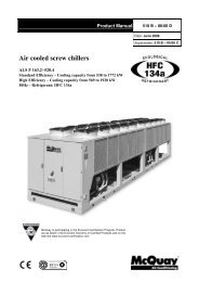
Operating limitsWMC XE-ST504540Condenser Leaving Water Temp. (°C)353025201510Operation <strong>with</strong> Glycol(below 4°C Evap LWT)500 2 4 6 8 10 12 14 16Evaporator Leaving Water Temp. (°C)Above diagram is indicative: for the operating limits of the specific models please refer to the WMC selectionsoftware.Notes:The operation <strong>with</strong> Glycol influences the unit performance: the WMC selection software is able to adjust the calculations keeping thisinto accountKPMWC00905-10EN - page 16/24
Dimensions WMC XE-STLegend1 - Electrical Panel2 - Power Connection Slot3 - Compressor4 - Evaporator Water Inlet5 - Evaporator Water Outlet6 - Condenser Water Inlet7 - Condenser Water OutletWMCDimensionsA B C D E (1) F (2) G H I L M N O100S 1276 3254 1822 1518 334 334 496 286 515 319 495 286 176125S 1276 3254 1822 1518 334 334 496 286 515 319 495 286 176150S 1276 3419 1822 1518 334 487 496 286 515 319 496 284 177(1) Condenser hydraulic connections(2) Evaporator hydraulic connectionsNote: the above drawing refers to size 150SKPMWC00905-10EN - page 17/24
Legend1 - Electrical Panel2 - Power Connection Slot3 - Compressor4 - Evaporator Water Inlet5 - Evaporator Water Outlet6 - Condenser Water Inlet7 - Condenser Water OutletWMCDimensionsA B C D (1) E (2) F G H I L M N200D 1790 3441 1755 487 334 546 284 542 319 522 360 203250D 1853 3289 1748 334 334 546 360 496 383 585 360 203300D 1904 3401 1794 334 411 598 360 474 383 609 413 227(1) Condenser hydraulic connections(2) Evaporator hydraulic connectionsNote: the above drawing refers to size 300DKPMWC00905-10EN - page 18/24
Installation notesWarningInstallation and maintenance of the unit must to be performed only by qualified personnel who have knowledge <strong>with</strong> localcodes and regulations, and experience <strong>with</strong> this type of equipment. Must be avoided the unit installation in places thatcould be considered dangerous for all the maintenance operations.HandlingCare should be taken to avoid bumping and/or jolting during unloading from the lorry and moving the unit. Do not push orpull the machine from any part other than the base frame. Secure the machine inside the lorry to prevent it from movingand causing damage to the panels and to the base frame. Do not allow any part of the unit to fall during transportation orunloading, as this could cause serious damage.All units of the series are supplied <strong>with</strong> lifting points marked in yellow. Only these points may be used for lifting the unit,as shown in the following figure (the picture is indicative, so lifting tools are not supplied)LocationAll units are designed for indoor installations. The machine must be installed on a robust and perfectly level foundation;should the machine be installed on balconies or roofs, it might be necessary to use weight distribution beams.For installation on the ground, a strong cement base that is at least 250 mm wider and longer than the machine must beprepared. Also, this base must be strong enough to support the weight of the machine as stated in the technicalspecifications.If the machine is installed in places that are easily accessible to people and animals, it is advisable to install protectiongratings for the compressor section.To ensure the best possible performance on the installation site, the following precautions and instructions must befollowed:• Make sure to provide a strong and solid foundation to reduce noise and vibration as much as possible.KPMWC00905-10EN - page 19/24
• The water in the system must be particularly clean and all traces of oil or rust must be removed. A mechanical waterfilter must be installed on the machine’s inlet piping.Space requirementsEvery side of the machine must be accessible for all post-installation maintenance activities.In particular, service clearance has to be provided at one end of the unit for possible removal of evaporator and/orcondenser tubes. Evaporator and condenser tubes are rolled into the tube sheets to permit replacement if necessary; thelength of the vessel must be allowed at one end (doors or removable wall sections can be utilized). Keep a free space toallow the opening of electrical panel doors. Minimum clearance at all sides, including the top, is (1 meter); localregulation may require larger clearance.The above recommended information are representative of general installation. A specific evaluation should be done bycontractor depending on the case.KPMWC00905-10EN - page 20/24
Technical Specification for <strong>Oil</strong> <strong>Free</strong> <strong>Centrifugal</strong> Water Cooled<strong>Chiller</strong>GENERALThe <strong>Oil</strong> free <strong>Centrifugal</strong> water cooled chiller will be designed and manufactured in accordance <strong>with</strong> following Europeandirectives:Construction of pressure vessel 97/23/EC (PED)Machinery Directive2006/42/ECLow Voltage2006/95/ECElectromagnetic Compatibility2004/108/ECElectrical & Safety codes EN 60204–1 / EN 60335-2-40Manufacturing Quality Stds UNI – EN ISO 9001:2004The unit will be tested at full load in the factory at the nominal working conditions and water temperatures. Beforeshipment a full test will be held to avoid any losses.<strong>Chiller</strong> will be delivered to the job site completely assembled and charged <strong>with</strong> right refrigerant.Comply <strong>with</strong> the manufacturer instructions for rigging and handling equipment.The unit will be able to start up and operate as standard at full load and condenser entering fluid temperature from .… °Cto .… °C <strong>with</strong> an evaporator leaving fluid temperature between …. °C and ….. °CREFRIGERANTOnly HFC 134a will be accepted.PERFORMANCE Number of <strong>Oil</strong> free <strong>Centrifugal</strong> water cooled chiller: ............... Cooling capacity for single <strong>Oil</strong> free <strong>Centrifugal</strong> water cooled chiller: ............... kW Power input for single <strong>Oil</strong> free <strong>Centrifugal</strong> water cooled chiller in cooling mode: ............... kW Flooded Shell & tube evaporator entering water temperature in cooling mode: ............... °C Flooded Shell & tube evaporator leaving water temperature in cooling mode: ............... °C Flooded Shell & tube evaporator water flow: ............... l/s Flooded Shell & tube condenser entering water temperature in cooling mode: ............... °C Flooded Shell & tube condenser leaving water temperature in cooling mode: ............... °C Flooded Shell & tube evaporator water flow: ............... l/s Operating voltage range should be 400V ±10%, 3ph, 50Hz, voltage unbalance maximum 3%, <strong>with</strong>out neutralconductor and shall only have one power connection point.UNIT DESCRIPTION<strong>Chiller</strong> shall include as standard not less than: one refrigerant circuit, <strong>Oil</strong> free <strong>Centrifugal</strong> water cooled compressors (<strong>with</strong>integrated VFD), electronic expansion device (EEXV), flooded shell & tube heat exchangers, R134a refrigerant, controlsystem and all components necessary for safe and stable unit operation.<strong>Chiller</strong> will be factory assembled, protected by an epoxy paint.NOISE LEVEL AND VIBRATIONSSound pressure level at 1 meter distance in free field, semispheric conditions, shall not exceed ………dB(A). The soundpressure levels must be rated in accordance to ISO 3744.DIMENSIONSUnit dimensions shall not exceed following indications: unit length ............... mm unit width ............... mm unit height ............... mmKPMWC00905-10EN - page 21/24
CHILLER COMPONENTSCompressors1. The unit shall utilize magnetic bearing, oil-free, semi-hermetic centrifugal compressors. The compressor drivetrain shall be capable of coming to a controlled, safe stop in the event of a power failure.2. The motor shall be of the semi-hermetic type, of sufficient size to efficiently fulfill compressor horsepowerrequirements. It shall be liquid refrigerant cooled <strong>with</strong> internal thermal sensing devices in the stator windings. Themotor shall be compatible <strong>with</strong> variable frequency drive operation.3. The chiller shall be equipped <strong>with</strong> an integrated Variable Frequency Drive (VFD) to automatically regulatecompressor speed in response to cooling load and the compressor pressure lift requirement. Movable inlet guidevanes and variable compressor speed, shall provide unloading. The chiller controls shall coordinate compressorspeed and guide vane position to optimize chiller efficiency.4. Each compressor circuit shall be equipped <strong>with</strong> a line reactor to help protect against incoming power surges andhelp reduce harmonic distortion.EvaporatorWater side working pressure is designed for 10,5 bar. Vessels include 1” NPT spring loaded pressure relief valves. Shelland non-connection water heads are insulated <strong>with</strong> 3/4” thick closed cell insulation. Standard configuration on waterconnection side is 2 passes. The units will be equipped <strong>with</strong> a flooded shell-and-tube evaporator operating <strong>with</strong> refrigerant in shell and waterin tubes. Replaceable water tubes are fabricated from integral finned copper and mechanically bonded to steeltube sheets. The evaporator will have 1 circuit and standard configuration on water connection side is 2 passes. The water connections shall be VICTAULIC type connections as standard to ensure quick mechanicaldisconnection between the unit and the hydronic network. Evaporator is manufactured in accordance to PED approval.CondenserCondenser will be flooded shell-and-tube operating <strong>with</strong> refrigerant in shell and water in tubes. Replaceablewater tubes are fabricated from integral finned copper and mechanically bonded to steel tube sheets.The units will have one condenser on the refrigerant circuitStandard configuration on water connection side is 2 passes.The water connections shall be VICTAULIC type connections as standardCondenser is manufactured in accordance to PED approval.Refrigerant circuit The unit must have one refrigerant circuit. Each circuit shall include as standard: electronic expansion device piloted by unit’s microprocessor control,sight glass <strong>with</strong> moisture indicator and insulated suction line.Control panel1. The unit shall have a microprocessor-based control system consisting of a 15-inch VGA touch-screen operatorinterface and a unit controller.2. The touch-screen shall display the unit operating parameters, accept setpoint changes (multi-level passwordprotected) and be capable of resetting faults and alarms. The following parameters shall be displayed on thehome screen and also as trend curves on the trend screen:• Entering and leaving chilled water temperatures• Entering and leaving condenser water temperatures• Evaporator saturated refrigerant pressure• Condenser saturated refrigerant pressure• Percent of 100% speed (per compressor)• % of rated load amps for entire unit3. In addition to the trended items above, all other important real-time operating parameters shall also be shown onthe touch-screen. These items shall be displayed on a chiller graphic showing each component. At a minimum,the following critical areas must be monitored:• Compressor actual speed, maximum speed, percent speed• Evaporator water in and out temperatures, refrigerant pressure and temperature• Condenser water in and out temperatures, refrigerant pressure and temperatureKPMWC00905-10EN - page 22/24
• Liquid line temperature• Chilled water setpoint• Compressor and unit state and input and output digital and analog values4. A fault history shall be displayed using an easy to decipher, color coded set of messages that are date and timestamped. The alarm history shall be downloadable from the unit's USB port. An operating and maintenancemanual specific for the unit shall be viewable on the screen.5. All setpoints shall be viewable and changeable (multi-level password protected) on the touch screen and includesetpoint description and range of set values.6. Automatic corrective action to reduce unnecessary cycling shall be accomplished through preemptive control oflow evaporator or high discharge pressure conditions to keep the unit operating through abnormal transientconditions.7. Optionally, the factory mounted controller(s) shall support operation on a BACnet®, Modbus® or LONWORKS®network via one of the data link / physical layers listed below as specified by the successful Building AutomationSystem (BAS) supplier.• Modbus• BACnet MS/TP master (Clause 9)• BACnet IP• BACnet ISO 8802-3, (Ethernet)• LonTalk® FTT-10A. The unit controller shall be LONMARK ® certified.8. The information communicated between the BAS and the factory mounted unit controllers shall include thereading and writing of data to allow unit monitoring, control and alarm notification as specified in the unitsequence of operation and the unit points list.9. For chillers communicating over a LONMARK network, the corresponding LONMARK eXternal Interface File (XIF)shall be provided <strong>with</strong> the chiller submittal data.10. All communication from the chiller unit controller as specified in the points list shall be via standard BACnetobjects. Proprietary BACnet objects shall not be allowed. BACnet communications shall conform to the BACnetprotocol. A BACnet Protocol Implementation Conformance Statement (PICS) shall be provided along <strong>with</strong> the unitsubmittal. Field power connection, control interlock terminals, and unit control system should be centrally located in anelectric panel (IP 54). Power and starting controls should be separate from safety and operating controls indifferent compartments of the same panel. Operating and safety controls should include energy saving control; emergency stop switch; high and lowpressure cut-out switch (for each refrigerant circuit); anti-freeze thermostat; cut-out switch for each compressor.All of the information regarding the unit will be reported on a display and <strong>with</strong> the internal built-in calendar andclock that will switch the unit ON/OFF during day time all year long.The following features and functions shall be included:- leaving water temperature reset by controlling the water temperature Δt, by a remote 4-20mA DC signalor by controlling the external ambient temperature;- soft load function to prevent the system from operating at full load during the chilled fluid pulldown period;- password protection of critical parameters of control;- start-to-start and stop-to-start timers to provide minimum compressor off-time <strong>with</strong> maximum motorprotection;- communication capability <strong>with</strong> a PC or remote monitoring;- discharge pressure control through intelligent cycling of condenser fans;- lead-lag selection by manual or automatically by circuit run hours;- double set point for unit version;- scheduling via internal time clock to allow programming of a yearly start-stop schedule accommodatingweekends and holidays.Optional High Level Communications Interface<strong>Chiller</strong> must be able to communicate to BMS (Building Management System) based on the most common protocols as:• ModbusRTU• LonWorks, now also based on the international 8040 Standard <strong>Chiller</strong> Profile and LonMark Technology• BacNet BTP certifief over IP and MS/TP (class 4) (Native)• Ethernet TCP/IP.KPMWC00905-10EN - page 23/24
“The present publication is drawn up by of information only and does not constitute an offer binding upon <strong>McQuay</strong>. <strong>McQuay</strong> has compiled the content ofthis publication to the best of its knowledge. No express or implied warranty is given for the completeness, accuracy, reliability or fitness for particularpurpose of its content, and the products and services presented therein. Specifications are subject to change <strong>with</strong>out prior notice. <strong>McQuay</strong> explicitly rejectsany liability for any direct or indirect damage, in the broadest sense, arising from or related to the use and/or interpretation of this publication. All content iscopyrighted by <strong>McQuay</strong>.”<strong>McQuay</strong> partecipa al programma diCertificazione Eurovent.I prodotti interessati figurano nella GuidaEurovent dei Prodotti Certificati.<strong>McQuay</strong> is participating in the EuroventCertification ProgrammeProduct are as listed in the EuroventDirectory of Certified Products<strong>McQuay</strong> Italia S.P.A.Via Piani di s. Maria, 72 – 00040 Ariccia (Roma) Italia – Tel. (06) 937311 – Fax (06) 9374014www.mcquayeurope.comKPMWC00905-10EN - page 24/24