Sonic Tension MeterMANUAL - Rydell Industrial
Sonic Tension MeterMANUAL - Rydell Industrial
Sonic Tension MeterMANUAL - Rydell Industrial
- No tags were found...

You also want an ePaper? Increase the reach of your titles
YUMPU automatically turns print PDFs into web optimized ePapers that Google loves.
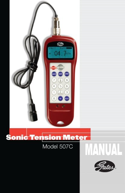
<strong>Sonic</strong> <strong>Tension</strong> MeterModel 507CMANUAL
<strong>Sonic</strong> <strong>Tension</strong> Meter Components507C MeterCord SensorOptional Inductive SensorOptional Flexible Sensor
ContentsImportant Warnings . . . . . . . . . . . . . . . . . . . . . . . . . . . .2Operating Instructions . . . . . . . . . . . . . . . . . . . . . . . . . .4Operating Theory . . . . . . . . . . . . . . . . . . . . . . . . . . . . .10Belt Mass Constants . . . . . . . . . . . . . . . . . . . . . . . . . . .11Belt Installation <strong>Tension</strong> . . . . . . . . . . . . . . . . . . . . . . . . .13Tips on Using the Gates <strong>Sonic</strong> <strong>Tension</strong> Meter . . . . . . . .13Meter Re-Calibration for Non-Standard Belts . . . . . . . . .15Summary of Features . . . . . . . . . . . . . . . . . . . . . . . . . . .15Optional Accessories . . . . . . . . . . . . . . . . . . . . . . . . . . .15Warranty, Service and Certification . . . . . . . . . . . . . . . .161
Thank you for purchasing theGates <strong>Sonic</strong> <strong>Tension</strong> Meter.Please read this manual thoroughly tofully utilize all the functions of this meter.Important Warnings• Do not drop this unit. Impact of any kind can result in damage.• Do not put water, solvent or any other liquids on this unit.• Do not leave this unit in a dusty environment.• Do not leave this unit where it will get hot, such as in a car or in direct sunlight.• Do not use volatile solvents to clean this unit.• Do not use this in an area where a spark could cause an explosion.• Do not pull hard on the cord of the sensor (microphone) from either end.• Do not use this unit outside during a thunderstorm, turn off power and seek asafe place. Non-compliance could result in electric shock from thunderbolt.• Do not bend the flexible arm sensor (microphone) within 20 mm (3/4 inch) ofeither end, because the construction is tubular, and the flexible arm sensor shouldnot be bent at sharp angles.2
Cord type measurement sensor(microphone) standard.One-touch connectorLCD screen withback light“MEASURE” keyPower keyWIDTH keyMASS key(unit mass)SPAN keyUP DOWN buttons(frequency rangeselection)0-button(frequency range switchingSelect keyHertz key(switching frequencyand tension)L E D Indicator lights(Left: redRight: green)Power supply: 2ea. AAA size batteries3
Operating InstructionsAttaching SensorEach of the male and female connectors has a notch on the surface. Fit theconnectors together at the notch and push them together. To disconnect,hold the collar on the sensor and pull out.Turn on the powerPress the "Power" key and the LCD screen display appears as follows:1235 461 – “MASS”2 – “WIDTH”3 – “SPAN”4 – Storage Register Number5 – Frequency Setting6 – Battery Level MeterThe LCD screen is back lit for use in low light conditions. The screen andback light remain on for up to five minutes of inactivity, and then the unitautomatically turns off.The opening screen displays the contents of the data storage register thatwas last being used when the STM was turned off. Values for (1) “MASS”(Belt Mass Constant), (2) “WIDTH” (Belt Width), and (3) “SPAN” ( BeltSpan Length) are all displayed simultaneously.Important Note: Reasonable non-zero belt constant values must be used inthe storage registers in order to receive belt tension readings. The unit willdisplay span frequency values regardless of the belt constants entered, butwill display “Error” and the red light will remain on if the calculated belttension value is beyond the display range of the screen.Pointer (4) indicates the data storage register number where current beltdata is saved. To change the data or storage register number, refer to“Input Data Storage and Retrieval” on page 7.Pointer (5) represents the current frequency filter setting. To change, referto “Frequency Filter Settings” on page 7.Pointer (6) indicates the battery level meter. A dark battery symbol indicatesa full charge. When the battery level becomes critically low, themeter indicator as well as a “Low Batt” message both blink.4
Enter belt massM = . g/mBelt mass constants are provided on pages 11 and 12 of this manual.Capacity available for input is from 000.1 to 999.9 grams/meter. Press the“MASS” key and enter numbers on the keypad. Make sure the decimal isplaced correctly in the display panel. If your entry is incorrect, press“MASS” again and the cursor returns to the original position.Enter belt width or number of rib/strandsW = . mm/#RCapacity available for input is from 000.1 to 999.9 millimeters or numberof ribs or strands.For a Synchronous belt, enter the belt width in millimeters.For an <strong>Industrial</strong> V-belt, enter the number of belts being measured.For a PolyFlex ® JB ® belt, enter the number of belts being measured.For a Micro-V ® belt, enter the total number of ribs.For a 21 mm wide Poly Chain ® belt, enter “021.0”;For a 1” wide PowerGrip ® timing belt, enter “025.4”;For a single strand <strong>Industrial</strong> V-belt, enter “001.0”.When using the <strong>Sonic</strong> <strong>Tension</strong> Meter on drives with multiple single orPowerBand ® belts, be sure to use the appropriate mass constant and enterthe correct number of belt strands being measured. There is no need tomultiply the mass constant by the number of ribs/strands, as the <strong>Sonic</strong><strong>Tension</strong> Meter will calculate the correct total belt mass.Example:For a V-belt drive using four individual 3V belts enter “1” for the beltwidth (“Width” key). The <strong>Sonic</strong> <strong>Tension</strong> Meter will display the staticbelt tension per individual belt. When measuring the belt tension in theV-belt drive, make sure the V-belts do not interfere with each other whilevibrating.If the same drive used a 4-strand 3V PowerBand ® belt instead of singlebelts enter “4” for the belt width (“Width” key). The total belt tension forall four belts is measured as the entire belt vibrates. The <strong>Sonic</strong> <strong>Tension</strong>Meter will display the total static belt tension for the PowerBand ® belt (forall strands within belt).5
Enter the span lengthS = mmCapacity available for input is from 000.1 to 999.9 millimeters. The spanlength represents the distance between the contact points on adjacentsprockets/pulleys/sheaves. This distance may be measured directly, or it maybe calculated from the formula below. Calculating the span length providesthe most accurate results.Span Length FormulaS =Where: S = Span Length (mm)CD = Center Distance (mm)D = Large Pulley Diameter (mm)d = Small Pulley Diameter (mm)Input Data Storage and RetrievalMass, width and span values can be stored for up to 20 different drive systems.Press the “SELECT” key to toggle through the 20 storage registers.Storage registers can also be recalled by simply pressing the “Select” keyand the number that corresponds to the storage register. The storage registernumber is displayed in the upper left hand corner of the LCD screen;Pointer (4) on page 5.The contents of all three data registers is displayed simultaneously. Thecontents of a register can be changed by simply pressing the mass, width,or span key and entering a new value. The new value is automaticallysaved if the storage register is changed, or the meter is turned off.Frequency Filter Settings and RangesA frequency filtering feature is available to focus the meter frequencymeasurement response to a narrower range. This can be useful in improvingthe response of the meter, and in filtering out potentially interferingbackground noise.Holding down the “0” button for 1-2 seconds will display a menu thatallows the frequency measurement range to be changed. The availableranges are as follows:HighStandardLow(D-d) 2CD 2 -4500 – 5000 Hz10 – 600 Hz10 – 50 Hz6
The default setting is the “Standard” range, and can be changed bypressing the “UP” and “DOWN” keys. To accept the highlighted range,press the “MEASURE” key. Note the letter in the upper left hand cornerof the LCD display indicates the frequency range setting Pointer (5) onpage 5; H - High, S - Standard, L - Low.Microphone Gain SettingThe microphone gain level is set automatically when the unit is turned on,based upon environmental background noise. If maximum microphonesensitivity is desired, turn the meter on without the microphone attachedand wait for the meter to power up. Then connect the microphone sotension measurements can be taken.MeasurementPress the “MEASURE” key and the green LED light will begin flashing. Tapthe belt span to make the belt span vibrate. Hold the sensor approximately1 cm (0.4 inch) from the belt or closer without touching the belt. Thegreen LED light will continue to flash until a signal is received by the sensor,then the green LED light will turn off and a wave-form graphic willappear on the LCD screen. After the signal is processed, the measured belttension is displayed, the meter beeps three times, and the green LED lightturns on indicating a successful tension measurement.After a tension reading has been obtained, pressing the “Hz” key togglesthe LCD display output between tension, frequency, or both.If the belt signal cannot be measured, or the measured frequency or thecalculated belt tension is out of the range of the meter, the red LED lightwill turn on. When this occurs, either the tension or frequency fields mayalso display ERROR.To make another tension reading, simply tap the belt again. The auto-triggerfeature will automatically re-activate the meter without pressing the“MEASURE” key.<strong>Tension</strong> DisplayT = Kg f or lb f or NThe displayed output of measured force can be switched between units ofKilograms force, Pounds force, and Newtons. This can be accomplished asfollows:With the unit powered off, press the “0” and “9” and “Power” keys atthe same time. The meter will then turn on with the current unit of measuredisplayed. Units can then be changed by pressing the "SELECT" key7
until the desired unit appears. Press and hold down the “POWER” keyagain until the meter turns off. Now turn the meter on for normal operation.Data entered into the unit must still be in SI units of millimeters andgrams.The capacity available for output is 99,900 Pounds force, Kilograms force,or Newtons.Frequency DisplayF = HzPressing the “Hz” key toggles the LCD display output between tension,frequency, or both.Measurement ErrorsIf either the calculated belt tension or measured frequency cannot be displayedthe red LED light will turn on and the LCD screen may display“ERROR”. If an error has been made in the measurement, “ERROR” will bedisplayed. Check the accuracy of the mass constants, width and span valuesand retry the measurement until a tension or frequency value isdisplayed. With the auto-trigger feature it is not necessary to press the“Measure” key again.When a tension or frequency reading is obtained, take at least two additionalreadings for comparison. Three readings in relative close proximityindicate reasonably accurate belt tension readings.<strong>Tension</strong> measurements made on belts at very low tensions may yieldgreater variability and a greater probability for errors. If a tension readingcannot be obtained, the belt may be too loose to generate a clear harmonicfrequency signal. If this is the case, the belt may need to betightened in order to obtain a tension reading. The optional InductiveSensor is more effective at very low frequencies than the conventionalmicrophone sensors, and may provide better results.NOTE: Frequency only readings must have data values in the storage registersor the meter’s red LED light will stay on.Battery GaugeA battery graphic is located in the upper-right hand corner of the LCDscreen. This gauge provides an estimate of the remaining battery power.A dark filled graphic indicates a full charge. When the battery levelbecomes critically low, the meter indicator as well as a “Low Batt”message both blink.8
Optional SensorsThe 507C <strong>Sonic</strong> <strong>Tension</strong> Meter comes equipped with a cord type sensor.The cord type sensor provides the most effective results.An optional flexible stick-type sensor allows one hand operation, but it issometimes difficult to hold the meter and sensor still enough to maintainclose and consistent clearance between the vibrating belt span and thesensor.An optional Inductive Sensor relies on a magnetic field rather than onsound waves. This allows tension measurements to be taken in both noisyand windy environments. In order for the Inductive Sensor to function, amagnetic field must be present on the belt. This can be easily accomplishedby taping a small magnet to the back of the belt.9
<strong>Sonic</strong> <strong>Tension</strong> Meter Operating TheoryWhen an impulse is applied to a belt span, it first oscillates in all modes ofvibration, but the higher frequencymodes decay fasterthan the fundamental mode.This leaves a continuous sinusoidalwave that is related toa specific belt tension; notediagram.Using a microcomputer, adata processing method tocapture a belt's natural oscillationfrequency wasdeveloped. Using thismethod, the wave form frequencycan be determinedeasily.The new system uses special sensors to detect belt oscillation wave forms.Data from these sensors is sent to the microcomputer inside the <strong>Sonic</strong><strong>Tension</strong> Meter for processing and conversion into the natural frequency. Tocalculate belt tension, the <strong>Sonic</strong> <strong>Tension</strong> Meter system uses the “transversevibration of strings theory.” To operate the meter, the belt mass, spanlength and width of the belt must be entered.Formula:Where:T = 4 x M x W x S 2 x f 2 x 10 -9T = Belt span tension (Newtons)M = Belt mass constant (gf/m/mm)W = Belt width (mm) or number of belt strandsS = Length of the span to be measured (mm)f = Natural frequency of the belt (Hz)Unlike a string, belts have cross-sectional rigidity. Therefore, tension valuesmeasured by the meter may be higher than the actual belt tension,depending on the operating conditions under which the effects of rigidityarise. When the actual belt tension must be more precisely measured, asimple calibration test may be necessary.10
Belt Mass ConstantsAdjusted mass constants are forstandard stock belts only. Non-standardbelt constructions may yieldinaccurate results and may requirespecial adjusted mass constants orspecial calibration procedures. Unitsare grams/meter per mm of width.Poly Chain ® GT ®and GT ® 2 Beltsg/m5M (5mm)........................3.08M (8mm)........................4.714M (14mm)....................7.9PowerGrip ®GT ® 2 Beltsg/m2M (2mm)........................1.43M (3mm)........................2.85M (5mm)........................4.18M (8mm)........................5.514M (14mm)....................9.620M (20mm)..................12.8Twin Power 3M................2.7Twin Power 5M................4.6Twin Power 8M................6.9Twin Power 14M............11.4PowerGrip ®GT ® Beltsg/m8M (8mm)........................5.814M (14mm)....................9.7PowerGrip ®HTD ® Beltsg/m3M (3mm)........................2.45M (5mm)........................3.98M (8mm)........................6.214M (14mm)....................9.920M (20mm)..................12.8Twin Power 3M................2.7Twin Power 5M................4.6Twin Power 8M................7.2Twin Power 14M............12.3PowerGrip ®Timing Beltsg/mMXL (0.080") ..................1.3XL (0.200")......................2.4L (0.375") ........................3.2H (0.500") ......................3.9XH (0.875") ..................11.3XXH (1.25") ..................14.9Twin Power XL ................1.9Twin Power L ..................3.2Twin Power H ..................4.6For a single V-belt, enter 1rib/strand. When measuring aPowerBand ® (multiple) rib/strandbelt, enter the number ofribs/strands per belt. Units aregrams/meter per rib or strand.Super HC ® V-Belts g/m3V ....................................725V ..................................2008V ..................................5103VX ..................................615VX ................................158Super HC ®PowerBand ® Belts g/m3V ..........................96/strand5V ........................241/strand8V ........................579/strand3VX........................70/strand5VX......................185/strandPredator ® Beltsg/m3VP ........................89/strand5VP ....................217/strand8VP ......................528/strandBP ........................212/strandCP ........................332/strand11
Hi Power ® II Belts g/mA ......................................96B ....................................168C ....................................276D ....................................554E ....................................799Hi Power ® IIPowerBand ® Belts g/mA..........................151/strandB ..........................200/strandC..........................342/strandD..........................663/strandTri-Power ® Beltsg/mAX ....................................85BX ..................................144CX ..................................232Hi Power ® IIDubl-V Beltsg/mAA ..................................125BB ..................................194CC ..................................354DD ................................ 750Power Cable ® Belts g/mA ....................................108B ....................................172C ....................................302Metric Power V-Belts -Lengths ≤ 3000mm g/mXPZ ..................................51XPA ..................................87XPB ................................156XPC ................................24910X ..................................4413X ..................................8617X ................................139Metric Power V-Belts -Lengths > 3000mm g/mSPZ ..................................72SPA ................................115SPB ................................186SPC ................................33713X ................................10017X ................................171Micro-V ® Beltsg/mH ..................................5/ribJ ....................................7/ribK..................................18/ribL ..................................29/ribM ..............................109/ribTruflex ® Beltsg/m2L ....................................223L ....................................444L ....................................775L ..................................125PoweRated ® Belts g/m67 (3L) ..............................5268 (4L) ..............................8369 (5L) ............................138Polyflex ® Beltsg/m3M......................................45M....................................107M....................................2411M..................................49Polyflex ® JB ® Belts g/m3M .......................... 5/strand5M ........................11/strand7M ........................30/strand11M ......................64/strand12
Belt Installation <strong>Tension</strong>Proper belt installation tension is essential in V-belt and synchronous drivesfor optimum performance and reliability. The correct installation tension fora belt, or set of belts, depends upon the drive geometry and load conditionsand must be calculated. Procedures for calculating belt tension areincluded in the appropriate drive design manual. To determine the belt tensionrecommended for specific drive applications, either refer to theappropriate belt drive design manual or to the DesignFlex II belt drive selectionprogram located at: http://www.gates.com/designflexThe following belt drive design manuals listed below may be helpful:Poly Chain ® GT ® 2 Belt Drive Design Manual No. 17595Light Power and Precision Drives No. 17183Heavy-Duty V-Belt Drive Design Manual No. 14995-APowerGrip ® GT ® 2 Belt Systems No. 17195These catalogs can be downloaded from the www.gates.com website byfollowing the links for catalogs under the <strong>Industrial</strong> Power Transmissionheadings, or contact Gates Application Engineering at (303) 744-5800.Tips on Using the <strong>Sonic</strong> <strong>Tension</strong> MeterThe Gates <strong>Sonic</strong> <strong>Tension</strong> Meter is capable of measuring belt tension withgreater accuracy and consistency than traditional methods. It should not,however, be expected to produce exacting results in every case. Whilenumerous factors can be found to influence the accuracy of the meter'soutput, one must remember that traditional methods of belt tensioningsuch as force/deflection or belt elongation are approximate.The following suggestions are provided to help you achieve a high level ofaccuracy with the Gates <strong>Sonic</strong> <strong>Tension</strong> Meter:Consistent Readings• After the correct constants have been entered into the meter, take atleast three readings to confirm that results are consistent and the meteris not erroneously reading background noise.Minimum Belt Span Length• When measuring the tension in synchronous belts, use spans that aremore than 20 times the length of the tooth pitch. Using spans shorterthan this may result in readings that are higher than the actual tensiondue to belt cross-sectional stiffness.• When measuring the tension in V-belts, use spans that are more than 30times the belt top width. Using spans shorter than this may result inreadings that are higher than the actual tension due to belt cross-sectionalstiffness.13
Minimum Belt <strong>Tension</strong>• There are limits as to how low a span tension value the meter can measuredepending upon the belt type and cross section. Minimumrecommended installation tension values are available for all belt sectionsfrom either drive design manuals or Gates Application Engineering.Attempting to measure belt tensions below these minimum recommendedvalues should be avoided, as the meter may display “Error” orprovide inaccurate results. If the belt span tension is low, and a tensionreading cannot be obtained, try increasing the belt tension and then takeanother reading.New Belt Installation• Before measuring belt installation tension, turn the drive over by handfor several revolutions to fully seat the belt and equalize tension in all ofthe belt spans. Factors such as sprocket/shaft eccentricity, belt/sheavegroove irregularity, etc., can influence belt tension as the sprockets orsheaves rotate. If the measured belt tension changes significantly as thedrive is rotated, and accurate measurements are needed, determine thelow and high values and average them together.Windy Environment• Wind can adversely affect the ability of the meter to make a reading bycreating excessive background noise. If measuring in a windy location,the Inductive Sensor should be used instead of a microphone sensor.Inductive Sensor• An optional Inductive Sensor should be utilized in noisy or windy environmentsfor optimal results. The Inductive Sensor uses a magnetic fieldrather than sound waves.A simple way to use this sensor is with a magnet taped to the backsideof the belt. Small “rare earth” magnets provide excellent results withminimal influence on the belt span frequency due to the added weight.Using Frequency Mode• If an assembly process is used to set belt tension in a particular application,and the meter is used only to monitor belt installation tensions, thefrequency mode can be used rather than displaying an absolute measuredtension value. Belt span frequencies for minimum and maximumtension conditions can be measured so assemblers/technicians can usethe meter to verify that belt installation tension is within an acceptablerange.14
Re-calibration for Non-Standard BeltsMeasuring the tension of special belts with extra thick backings, alternatematerials, etc., may yield less than accurate results using belt mass constantsfor standard belts. In these cases, a simple calibration process maybe used. The belting can be placed on a fixture with a known span lengthunder various known tensions (hanging weights can be used). By takingfrequency measurements at various tensions, span frequency vs. tensiondata can be collected.This data can then be used in a graphical format or in equation form toconvert measured span vibration frequencies to accurate belt tensions.Data of this type is specific to each application and cannot be applied todrives with different span lengths. Because the resulting data may not belinear, it is best to measure the tension of non-standard belts in terms offrequency rather than deriving new belt mass constants to measure interms of absolute tension.Summary of Features• Model 507C - Product No. 7420-0507• Includes cord type sensor - Product No. 7420-0206.• 20 Memory Registers for Belt Constants• Max Frequency of 5000 Hz• Auto Microphone Gain Control• Variable Frequency Range Filters• Auto Shut Off - The meter will automatically shut off after 5 minutes ofinactivity. Power can be shut off manually by pressing and holding thepower button for 1-2 seconds.• Batteries - 2 each; AAA. The battery compartment can be found on thebackside of the meter.Optional Accessories• Flexible Sensor -Product No. 7420-0204Makes single-handed operation possible.• Inductive Sensor -Product No. 7420-0212Recommended for noisy or windy environments.Magnets included.15
Warranty, Service and CertificationThank you for using the Gates <strong>Sonic</strong> <strong>Tension</strong> Meter. Gates warrants themeter to successfully operate for a period of one year (or six months forthe sensors) from the date of purchase and will repair any defects forwhich Gates is responsible without charge within this period.For meter calibration/certification and warranty needs contact:Reata Engineering7822 S. Wheeling Court. Suite. AEnglewood, Colorado 80112Phone: (303) 936-1350Fax: (303) 935-5956NOTE: Reata Engineering charges for re-calibration/certification.Unit Conversion Formulaslb f x 4.4482 = N x 0.2248 = lb flb f x 0.4536 = kg f x 2.2046 = lb fN x 0.1020 = kg f x 9.8067 = Nlb f = Pounds forceN = Newtons forceKg f = Kilograms forceInches x 25.4000 = mmmm x 0.0394 = inchesmm = MillimetersSpan Length FormulaS =(D-d) 2CD 2 -4Where:S = Span Length (mm)CD = Center Distance (mm)D = Large Pulley Diameter (mm)d = Small Pulley Diameter (mm)16
www.gates.com/stmFor technical information on Model 507C:Phone: 303.744.5800 • Fax: 303.744.4600 • E-mail: ptpasupport@gates.comTo locate a distributor:visit www.gates.com/industrial and click on “U.S. Distributors”Gates Corporation • Denver, Colorado 802021717898-C 08/04