EN / ACS800-17 Drives Hardware Manual - Simark Controls
EN / ACS800-17 Drives Hardware Manual - Simark Controls
EN / ACS800-17 Drives Hardware Manual - Simark Controls
- No tags were found...

Create successful ePaper yourself
Turn your PDF publications into a flip-book with our unique Google optimized e-Paper software.
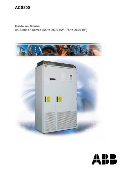
<strong>ACS800</strong><strong>Hardware</strong> <strong>Manual</strong><strong>ACS800</strong>-<strong>17</strong> <strong>Drives</strong> (55 to 2500 kW / 75 to 2800 HP)
<strong>ACS800</strong>-<strong>17</strong> <strong>Drives</strong>55 to 2500 kW (75 to 2800 HP)<strong>Hardware</strong> <strong>Manual</strong>3AFE68397260 REV B <strong>EN</strong>EFFECTIVE: 26.10.2005© 2005 ABB Oy. All Rights Reserved.
1Update NoticeThe notice concerns the following <strong>ACS800</strong>-<strong>17</strong> <strong>Drives</strong> (55to 2500 kW / 75 to 2800 HP) <strong>Hardware</strong> <strong>Manual</strong>s:Code Revision Language3AFE68397260 B English <strong>EN</strong>3AFE68637546 B German DE3AFE68637562 B Spanish ES3AFE68506581 B French FR3AFE68637554 B Italian ITCode: 3AUA0000059449 Rev AValid: from 01.02.2010 until the release of the next revision ofthe manualContents:The headings in this update notice refer to the modifiedsubsections in the original English manual. Each heading alsoincludes a page number and a classifier NEW, CHANGED, orDELETED. The page number refers to the page number in theoriginal English manual. The classifier describes the type ofthe modification.NEW (page 6): Safety / Installation and maintenance work• After maintaining or modifying a drive safety circuit or changing circuit boardsinside the module, retest the functioning of the safety circuit according to thestart-up instructions.• Do not change the electrical installations of the drive except for the essentialcontrol and power connections. Changes may affect the safety performance oroperation of the drive unexpectedly. All customer-made changes are on thecustomer's responsibility.[...]Note:• The Safe torque off function (option +Q968) does not remove the voltage from themain and auxiliary circuits.NEW (page 9): Safety / Operation• The Safe torque off function (option +Q968) can be used for stopping the drive inemergency stop situations. In the normal operating mode, use the Stop commandinstead.NEW (page 20): Terms and abbreviationsThe following term has been added to the Terms and abbreviations table:Term/AbbreviationASTOExplanationAn optional board within drives used to implement the Safe torque off function(option +Q968).Update Notice
2NEW/CHANGED (pages 39-40): Type codeThe table below contains the valid option code definitions for the emergency stop.CodeDescription+Q951 Emergency stop, stop category 0 with opening the main contactor/breaker+Q952 Emergency stop, stop category 1 with opening the main contactor/breaker+Q963 Emergency stop, stop category 0 without opening the main contactor/breaker+Q964 Emergency stop, stop category 1 without opening the main contactor/breaker SS1NEW (pages 39-40): Type codeThe table below contains the new option code definition for the Safe torque offfunction.CodeDescription+Q968 Safe torque off (STO) with a safety relayNEW (page 63): Emergency stopNote: If you add or modify the wiring in the drive safety circuits, ensure that theappropriate standards (e.g. IEC 61800-5-1, <strong>EN</strong> 62061, <strong>EN</strong>/ISO 13849-1 and -2) andthe ABB guidelines are met. After making the changes, verify the operation of thesafety function by testing it.NEW (page 65): Safe torque offThe drive supports the Safe torque off (STO) function according to standards<strong>EN</strong> 61800-5-2:2007; <strong>EN</strong>/ISO 13849-1:2008, IEC 61508, and <strong>EN</strong> 62061:2005. Thefunction also corresponds to an uncontrolled stop in accordance with category 0 of<strong>EN</strong> 60204-1 and prevention of unexpected start-up of <strong>EN</strong> 1037.The STO may be used where power removal is required to prevent an unexpectedstart. The function disables the control voltage of the power semiconductors of thedrive output stage, thus preventing the inverter from generating the voltage requiredto rotate the motor (see the diagram below). By using this function, short-timeoperations (like cleaning) and/or maintenance work on non-electrical parts of themachinery can be performed without switching off the power supply to the drive.Update Notice
3Update Notice
4WARNING! The Safe torque off function does not disconnect the voltage of the mainand auxiliary circuits from the drive. Therefore maintenance work on electrical partsof the drive or the motor can only be carried out after isolating the drive system fromthe main supply.Note: The Safe torque off function can be used for stopping the drive in emergencystop situations. In the normal operating mode, use the Stop command instead. If arunning drive is stopped by using the function, the drive will trip and stop by coasting.If this is not acceptable, e.g. causes danger, the drive and machinery must bestopped using the appropriate stopping mode before using this function.Note concerning permanent magnet motor drives in case of a multiple IGBTpower semiconductor failure: In spite of the activation of the Safe torque offfunction, the drive system can produce an alignment torque which maximally rotatesthe motor shaft by 180/p degrees. p denotes the pole pair number.Note: If you add or modify the wiring in the drive safety circuits, ensure that theappropriate standards (e.g. IEC 61800-5-1, <strong>EN</strong> 62061, <strong>EN</strong>/ISO 13849-1 and -2) andthe ABB guidelines are met. After making the changes, verify the operation of thesafety function by testing it.NEW (page 101): On-load checksThe following information has been added to the procedure:ActionInformationCheck the correct operation of the emergency stopcircuits from each operating location.If the drive is equipped with the category 1emergency stop function (option +Q952 or +Q964),adjust the delay time of the emergency stop relayand the deceleration time of the drive emergencystop function. The factory default settings do notnecessarily meet the application needs.NEW (page 101): On-load checksThe following information has been added to the procedure:ActionCheck that the Safe torque off function (option+Q968, if installed) works:Additional informationOptional function. See deliveryspecific circuit diagrams.• Ensure that the drive can be run and stoppedfreely during the commissioning.• Stop the drive (if running), switch the input poweroff and isolate the drive from the power line by adisconnector.• Check the STO circuit connections against thecircuit diagram.Update Notice
1ErratumSome of the NEMA ratings for the <strong>ACS800</strong>-<strong>17</strong> presented on page 124 of the<strong>ACS800</strong>-<strong>17</strong> <strong>Drives</strong> (55 to 2500 kW / 75 to 2800 HP) <strong>Hardware</strong> <strong>Manual</strong>(3AFE68397260 REV B <strong>EN</strong>, 26.10.2005) are incorrect. These are the correctedratings.NEMA ratingsThe ratings for the <strong>ACS800</strong>-<strong>17</strong> with a 60 Hz supply are given below. The symbolsare described below the table.<strong>ACS800</strong>-<strong>17</strong> typeNominal ratingsI maxAP cont.maxHPNormal useI 2NAP NHPHeavy-dutyuseI 2hdAHeat dissipationAir flow NoiselevelP hdHP Btu/h ft 3 /min dBAThree-phase supply voltage 380 V, 400 V, 415 V, 440 V, 460 V or 480 V<strong>ACS800</strong>-<strong>17</strong>-0070-5 168 75 114 75 88 60 8200 295 73<strong>ACS800</strong>-<strong>17</strong>-0100-5 234 100 132 100 114 75 9600 295 73<strong>ACS800</strong>-<strong>17</strong>-0120-5 264 125 156 125 125 100 11600 295 73<strong>ACS800</strong>-<strong>17</strong>-0<strong>17</strong>0-5 291 150 192 150 156 125 20500 765 74<strong>ACS800</strong>-<strong>17</strong>-0210-5 356 200 240 200 183 150 27300 765 74<strong>ACS800</strong>-<strong>17</strong>-0260-5 438 250 302 250 226 150 30700 1860 75<strong>ACS800</strong>-<strong>17</strong>-0320-5 530 300 361 300 273 200 37600 1860 75<strong>ACS800</strong>-<strong>17</strong>-0400-5 660 350 437 350 340 250 47800 1860 75<strong>ACS800</strong>-<strong>17</strong>-0460-5 762 450 504 400 393 300 54700 1860 75<strong>ACS800</strong>-<strong>17</strong>-0510-5 863 500 571 450 445 350 61500 1860 75<strong>ACS800</strong>-<strong>17</strong>-0580-5 972 550 643 500 501 400 75100 1860 75<strong>ACS800</strong>-<strong>17</strong>-0780-5 1294 750 856 700 667 550 88800 3770 77<strong>ACS800</strong>-<strong>17</strong>-0870-5 1458 900 965 800 752 650 109000 3770 77<strong>ACS800</strong>-<strong>17</strong>-1140-5 1906 1150 1261 1050 982 850 147000 3770 77<strong>ACS800</strong>-<strong>17</strong>-1330-5 22<strong>17</strong> 1300 1467 1250 1143 1000 157000 6030 78<strong>ACS800</strong>-<strong>17</strong>-1640-5 2734 1650 1809 1550 1409 1250 219000 6030 78<strong>ACS800</strong>-<strong>17</strong>-2160-5 3608 2150 2387 2050 1860 1600 277000 7530 79Three-phase supply voltage 525 V, 575 V or 600 V<strong>ACS800</strong>-<strong>17</strong>-0160-7 192 125 127 125 99 100 27300 765 74<strong>ACS800</strong>-<strong>17</strong>-0200-7 218 150 144 150 112 125 30700 765 74<strong>ACS800</strong>-<strong>17</strong>-0260-7 301 200 193 200 150 150 41000 1860 75<strong>ACS800</strong>-<strong>17</strong>-0320-7 4<strong>17</strong> 250 268 250 209 200 51200 1860 75<strong>ACS800</strong>-<strong>17</strong>-0400-7 502 350 322 300 251 250 61500 1860 75<strong>ACS800</strong>-<strong>17</strong>-0440-7 571 400 367 350 286 300 64900 1860 75<strong>ACS800</strong>-<strong>17</strong>-0540-7 668 450 429 450 334 350 7<strong>17</strong>00 1860 75<strong>ACS800</strong>-<strong>17</strong>-0790-7 985 700 632 650 493 500 120000 3770 77<strong>ACS800</strong>-<strong>17</strong>-0870-7 1091 800 700 750 545 600 126000 3770 77<strong>ACS800</strong>-<strong>17</strong>-1050-7 1310 950 840 900 655 700 143000 3770 77<strong>ACS800</strong>-<strong>17</strong>-1330-7 1663 1250 1067 1150 831 900 184000 6030 78<strong>ACS800</strong>-<strong>17</strong>-1510-7 1879 1350 1206 1300 940 1050 212000 6030 78<strong>ACS800</strong>-<strong>17</strong>-1980-7 2480 1850 1591 <strong>17</strong>50 1240 1350 280000 7530 79<strong>ACS800</strong>-<strong>17</strong>-2780-7 3472 2600 2228 2450 <strong>17</strong>36 1900 362000 10550 79<strong>ACS800</strong>-<strong>17</strong>-2940-7 3680 2800 2362 2600 1840 2000 413000 11300 79PDM-184674-G15Erratum
2SymbolsNominal ratingsI max Maximum output current. Allowable for 10 seconds at start, otherwise as long as allowedby drive temperature.P cont.max Typical motor power. The power ratings apply to most 4-pole NEMA-rated motors atnominal voltage (460 or 575 V).Normal use (10% overloadability)I 2N Continuous rms current. 10% overload is allowed for 1 minute every 5 minutes.P N Typical motor power. The power ratings apply to most 4-pole NEMA-rated motors atnominal voltage (460 or 575 V).Heavy-duty use (50% overloadability)I 2hd Continuous rms current. 50% overload is allowed for 1 minute every 5 minutes.P hd Typical motor power. The power ratings apply to most 4-pole NEMA-rated motors atnominal voltage (460 or 575 V).Note: The ratings apply in an ambient temperature of 40 °C (104 °F). In lowertemperatures, the ratings are higher.Erratum
5Safety instructionsWhat this chapter containsThis chapter contains safety instructions you must follow when installing, operatingand servicing the drive. If ignored, physical injury or death may follow, or damagemay occur to the drive, the motor or driven equipment. Read the safety instructionsbefore you work on the unit.Usage of warnings and notesThere are two types of safety instructions throughout this manual: warnings andnotes. Warnings caution you about conditions which can result in serious injury ordeath and/or damage to the equipment, and advise on how to avoid the danger.Notes draw attention to a particular condition or fact, or give information on asubject. The warning symbols are used as follows:Dangerous voltage warning warns of high voltages which can causephysical injury and/or damage to the equipment.General warning warns about conditions, other than those caused byelectricity, which can result in physical injury and/or damage to theequipment.Electrostatic discharge warning warns of electrostatic discharge whichcan damage the equipment.Safety instructions
6Installation and maintenance workThese warnings are intended for all who work on the drive, motor cable or motor.Ignoring the instructions can cause physical injury or death, or damage theequipment.WARNING!• Only qualified electricians are allowed to install and maintain the drive.• The main switch on the cabinet door does not remove the voltage from the inputbusbars of the drive. Before working on the drive, isolate the whole drive fromthe supply.• Never work on the drive, the motor cable or the motor when main power isapplied. After switching off the input power, always wait for 5 min to let theintermediate circuit capacitors discharge before you start working on the drive,the motor or the motor cable. Measure the voltage between terminals UDC+and UDC- (L+ and L–) with a multimeter (impedance at least 1 Mohm) toensure that the drive is discharged before beginning work.• Apply temporary grounding before working on the unit.• Do not work on the control cables when power is applied to the drive or to theexternal control circuits. Externally supplied control circuits may causedangerous voltages to exist inside the drive even when the main power of thedrive is switched off.• Do not make any insulation or voltage withstand tests on the drive or drivemodules.• When reconnecting the motor cable, always check that the phase order iscorrect.• When joining shipping splits (if any), check the cable connections at the jointsbefore switching on the supply voltage.• Live parts on the inside of the doors are protected against direct contact.Special attention shall be paid when handling metallic shrouds.Note:• The motor cable terminals on the drive are at a dangerously high voltage whenthe input power is on, regardless of whether the motor is running or not.• The brake control terminals (UDC+, UDC-, R+ and R- terminals) carry adangerous DC voltage (over 500 V).• Depending on the external wiring, dangerous voltages (115 V, 220 V or 230 V)may be present on the relay outputs of the drive system.• The Prevention of Unexpected Start function does not remove the voltage fromthe main and auxiliary circuits.Safety instructions
7WARNING!• During the installation procedure, supply, filter or inverter modules may have tobe temporarily extracted from the cabinet. The modules have a high centre ofgravity. In order to minimise the danger of toppling over, keep the support legs(if provided) of the modules extended whenever manoeuvring the modulesoutside the cabinet. An overturning module can cause physical injury.Do not tilt!• Electrically conductive dust inside the unit may cause damage or lead tomalfunction. Make sure that dust from drilling does not enter the drive wheninstalling.• Fastening the cabinet by riveting or welding is not recommended. However, ifwelding is necessary, ensure the return wire is properly connected in order notto damage the electronic equipment in the cabinet. Also ensure that weldingfumes are not inhaled.• Ensure sufficient cooling of the unit.• Cooling fans may continue to rotate for a while after the disconnection of theelectrical supply.• Some parts inside the drive cabinet, such as heatsinks of powersemiconductors, remain hot for a while after the disconnection of the electricalsupply.WARNING!• The printed circuit boards contain components sensitive to electrostaticdischarge. Wear a grounding wrist band when handling the boards. Do nottouch the boards unnecessarily.Safety instructions
8GroundingThese instructions are intended for all who are responsible for the grounding of thedrive. Incorrect grounding can cause physical injury, death or equipment malfunctionand increase electromagnetic interference.WARNING!• Ground the drive, the motor and adjoining equipment to ensure personnelsafety in all circumstances, and to reduce electromagnetic emission and pickup.• Make sure that grounding conductors are adequately sized as required bysafety regulations.• In a multiple-drive installation, connect each drive separately to protectiveearth (PE).• Do not install a drive equipped with an EMC (line) filter to an ungroundedpower system or a high resistance-grounded (over 30 ohms) power system.Note:• Power cable shields are suitable for equipment grounding conductors onlywhen adequately sized to meet safety regulations.• As the normal leakage current of the drive is higher than 3.5 mA AC or 10 mADC (stated by <strong>EN</strong> 50<strong>17</strong>8, 5.2.11.1), a fixed protective earth connection isrequired.Fibre optic cablesWARNING!• Handle the fibre optic cables with care. When unplugging optic cables, alwaysgrab the connector, not the cable itself. Do not touch the ends of the fibres withbare hands as the fibre is extremely sensitive to dirt. The minimum allowedbend radius is 25 mm (1 in.).Safety instructions
9OperationThese warnings are intended for all who plan the operation of the drive or operatethe drive. Ignoring the instructions can cause physical injury or death or damage theequipment.WARNING!• Before adjusting the drive and putting it into service, make sure that the motorand all driven equipment are suitable for operation throughout the speed rangeprovided by the drive. The drive can be adjusted to operate the motor atspeeds above and below the speed provided by connecting the motor directlyto the power line.• Do not activate automatic fault reset functions of the Standard ApplicationProgram if dangerous situations can occur. When activated, these functionswill reset the drive and resume operation after a fault.• Do not control the motor with the disconnecting device (means); instead, usethe control panel keys and , or commands via the I/O board of the drive.The maximum allowed number of charging cycles of the DC capacitors (i.e.power-ups by applying power) is five in ten minutes.• Do not use the Prevention of Unexpected Start feature for stopping the drivewhen the inverter unit(s) is running. Give a Stop command instead.Note:• If an external source for start command is selected and it is ON, the drive (withStandard Application Program) will start immediately after fault reset unless thedrive is configured for 3-wire (a pulse) start/stop.• When the control location is not set to Local (L not shown in the status row ofthe display), the stop key on the control panel will not stop the drive. To stopthe drive using the control panel, press the LOC/REM key and then the stopkey .Safety instructions
10Permanent magnet motor drivesThese are additional warnings concerning permanent magnet motor drives.WARNING! Do not work on the drive when the permanent magnet motor is rotating.Also when the supply power is switched off, a rotating permanent magnet motorfeeds power to the intermediate circuit of the drive and also the supply connectionsbecome live (even when the inverter is stopped!).Installation and maintenance work• Disconnect the motor from the drive with a safety switchand additionally, if possible,• lock the motor shaft and ground the motor connection terminals temporarily byconnecting them together as well as to the PE.OperationDo not run the motor above the rated speed. Motor overspeed leads to overvoltagewhich may result in explosion of the capacitors in the intermediate circuit of the drive.Application programControlling a permanent magnet motor is only allowed using the <strong>ACS800</strong> PermanentMagnet Synchronous Motor Drive Application Program, or using other applicationprograms in scalar control mode only.Safety instructions
11Table of contentsSafety instructionsWhat this chapter contains . . . . . . . . . . . . . . . . . . . . . . . . . . . . . . . . . . . . . . . . . . . . . . . . . . . . . . . . 5Usage of warnings and notes . . . . . . . . . . . . . . . . . . . . . . . . . . . . . . . . . . . . . . . . . . . . . . . . . . . . . . 5Installation and maintenance work . . . . . . . . . . . . . . . . . . . . . . . . . . . . . . . . . . . . . . . . . . . . . . . . . . 6Grounding . . . . . . . . . . . . . . . . . . . . . . . . . . . . . . . . . . . . . . . . . . . . . . . . . . . . . . . . . . . . . . . . 8Fibre optic cables . . . . . . . . . . . . . . . . . . . . . . . . . . . . . . . . . . . . . . . . . . . . . . . . . . . . . . . . . . . 8Operation . . . . . . . . . . . . . . . . . . . . . . . . . . . . . . . . . . . . . . . . . . . . . . . . . . . . . . . . . . . . . . . . . . . . . . 9Permanent magnet motor drives . . . . . . . . . . . . . . . . . . . . . . . . . . . . . . . . . . . . . . . . . . . . . . . . . . . 10Installation and maintenance work . . . . . . . . . . . . . . . . . . . . . . . . . . . . . . . . . . . . . . . . . . . . . 10Operation . . . . . . . . . . . . . . . . . . . . . . . . . . . . . . . . . . . . . . . . . . . . . . . . . . . . . . . . . . . . . . . . 10Application program . . . . . . . . . . . . . . . . . . . . . . . . . . . . . . . . . . . . . . . . . . . . . . . . . . . . . . . . 10Table of contentsAbout this manualWhat this chapter contains . . . . . . . . . . . . . . . . . . . . . . . . . . . . . . . . . . . . . . . . . . . . . . . . . . . . . . . <strong>17</strong>Target audience . . . . . . . . . . . . . . . . . . . . . . . . . . . . . . . . . . . . . . . . . . . . . . . . . . . . . . . . . . . . . . . <strong>17</strong>Common chapters for multiple products . . . . . . . . . . . . . . . . . . . . . . . . . . . . . . . . . . . . . . . . . . . . . <strong>17</strong>Categorization according to the frame size . . . . . . . . . . . . . . . . . . . . . . . . . . . . . . . . . . . . . . . . . . . <strong>17</strong>Contents . . . . . . . . . . . . . . . . . . . . . . . . . . . . . . . . . . . . . . . . . . . . . . . . . . . . . . . . . . . . . . . . . . . . . <strong>17</strong>Installation and commissioning flowchart . . . . . . . . . . . . . . . . . . . . . . . . . . . . . . . . . . . . . . . . . . . . 18Inquiries . . . . . . . . . . . . . . . . . . . . . . . . . . . . . . . . . . . . . . . . . . . . . . . . . . . . . . . . . . . . . . . . . . . . . . 19Terms and abbreviations . . . . . . . . . . . . . . . . . . . . . . . . . . . . . . . . . . . . . . . . . . . . . . . . . . . . . . . . . 20The <strong>ACS800</strong>-<strong>17</strong>What this chapter contains . . . . . . . . . . . . . . . . . . . . . . . . . . . . . . . . . . . . . . . . . . . . . . . . . . . . . . . 23The <strong>ACS800</strong>-<strong>17</strong> . . . . . . . . . . . . . . . . . . . . . . . . . . . . . . . . . . . . . . . . . . . . . . . . . . . . . . . . . . . . . . . . 23Cabinet line-up . . . . . . . . . . . . . . . . . . . . . . . . . . . . . . . . . . . . . . . . . . . . . . . . . . . . . . . . . . . . 23Frame R6 . . . . . . . . . . . . . . . . . . . . . . . . . . . . . . . . . . . . . . . . . . . . . . . . . . . . . . . . . . . 24Frame R7i . . . . . . . . . . . . . . . . . . . . . . . . . . . . . . . . . . . . . . . . . . . . . . . . . . . . . . . . . . . 25Frame R8i . . . . . . . . . . . . . . . . . . . . . . . . . . . . . . . . . . . . . . . . . . . . . . . . . . . . . . . . . . . 26Swing-out frame . . . . . . . . . . . . . . . . . . . . . . . . . . . . . . . . . . . . . . . . . . . . . . . . . . . . . . . . . . . 27Cabling direction . . . . . . . . . . . . . . . . . . . . . . . . . . . . . . . . . . . . . . . . . . . . . . . . . . . . . . . . . . 29Single-line circuit diagram of the drive . . . . . . . . . . . . . . . . . . . . . . . . . . . . . . . . . . . . . . . . . . . . . . 31Operation principle . . . . . . . . . . . . . . . . . . . . . . . . . . . . . . . . . . . . . . . . . . . . . . . . . . . . . . . . . . . . . 32Line-side converter . . . . . . . . . . . . . . . . . . . . . . . . . . . . . . . . . . . . . . . . . . . . . . . . . . . . . . . . 32AC voltage and current waveforms . . . . . . . . . . . . . . . . . . . . . . . . . . . . . . . . . . . . . . . . 32Motor-side converter . . . . . . . . . . . . . . . . . . . . . . . . . . . . . . . . . . . . . . . . . . . . . . . . . . . . . . . 33Reduced run capability . . . . . . . . . . . . . . . . . . . . . . . . . . . . . . . . . . . . . . . . . . . . . . . . . . . . . 33<strong>Controls</strong> . . . . . . . . . . . . . . . . . . . . . . . . . . . . . . . . . . . . . . . . . . . . . . . . . . . . . . . . . . . . . . . . . . . . . . 34Control interfaces of the drive . . . . . . . . . . . . . . . . . . . . . . . . . . . . . . . . . . . . . . . . . . . . . . . . 34Door switches . . . . . . . . . . . . . . . . . . . . . . . . . . . . . . . . . . . . . . . . . . . . . . . . . . . . . . . . . . . . 35Table of contents
12Main switch-disconnector (Q1 in frame size R6 to R8i) . . . . . . . . . . . . . . . . . . . . . . . . .35Air circuit breaker (Q1 in frame size 2×R8i and up) . . . . . . . . . . . . . . . . . . . . . . . . . . . .35Auxiliary power switch (Q100 in frame size 2×R8i and up) . . . . . . . . . . . . . . . . . . . . . .35Earthing switch (Q9 in frame size 2×R8i and up) . . . . . . . . . . . . . . . . . . . . . . . . . . . . .35Other door switches . . . . . . . . . . . . . . . . . . . . . . . . . . . . . . . . . . . . . . . . . . . . . . . . . . . .35Control panel . . . . . . . . . . . . . . . . . . . . . . . . . . . . . . . . . . . . . . . . . . . . . . . . . . . . . . . . . . . . . .36To control the supply unit… . . . . . . . . . . . . . . . . . . . . . . . . . . . . . . . . . . . . . . . . . . . . . .36To control the inverter unit… . . . . . . . . . . . . . . . . . . . . . . . . . . . . . . . . . . . . . . . . . . . . .36Fieldbus control of the line-side converter . . . . . . . . . . . . . . . . . . . . . . . . . . . . . . . . . . . . . . .37Block diagram: reference select . . . . . . . . . . . . . . . . . . . . . . . . . . . . . . . . . . . . . . . . . .37Type code . . . . . . . . . . . . . . . . . . . . . . . . . . . . . . . . . . . . . . . . . . . . . . . . . . . . . . . . . . . . . . . . . . . . .38Frame sizes R6, R7i and R8i . . . . . . . . . . . . . . . . . . . . . . . . . . . . . . . . . . . . . . . . . . . . . . . . .38Frame sizes 2×R8i to 6×R8i . . . . . . . . . . . . . . . . . . . . . . . . . . . . . . . . . . . . . . . . . . . . . . . . . .39Mechanical installationWhat this chapter contains . . . . . . . . . . . . . . . . . . . . . . . . . . . . . . . . . . . . . . . . . . . . . . . . . . . . . . . .41General . . . . . . . . . . . . . . . . . . . . . . . . . . . . . . . . . . . . . . . . . . . . . . . . . . . . . . . . . . . . . . . . . . . . . . .41Required tools . . . . . . . . . . . . . . . . . . . . . . . . . . . . . . . . . . . . . . . . . . . . . . . . . . . . . . . . . . . . . . . . .41Moving the unit . . . . . . . . . . . . . . . . . . . . . . . . . . . . . . . . . . . . . . . . . . . . . . . . . . . . . . . . . . . . . . . . .42…by crane . . . . . . . . . . . . . . . . . . . . . . . . . . . . . . . . . . . . . . . . . . . . . . . . . . . . . . . . . . . . . . . .42…by fork-lift or pallet truck . . . . . . . . . . . . . . . . . . . . . . . . . . . . . . . . . . . . . . . . . . . . . . . . . . .43…on rollers . . . . . . . . . . . . . . . . . . . . . . . . . . . . . . . . . . . . . . . . . . . . . . . . . . . . . . . . . . . . . . .43Laying the unit on its back . . . . . . . . . . . . . . . . . . . . . . . . . . . . . . . . . . . . . . . . . . . . . . . . . . . .43Final placement of the unit . . . . . . . . . . . . . . . . . . . . . . . . . . . . . . . . . . . . . . . . . . . . . . . . . . .44Before installation . . . . . . . . . . . . . . . . . . . . . . . . . . . . . . . . . . . . . . . . . . . . . . . . . . . . . . . . . . . . . . .45Delivery check . . . . . . . . . . . . . . . . . . . . . . . . . . . . . . . . . . . . . . . . . . . . . . . . . . . . . . . . . . . . .45Installation procedure . . . . . . . . . . . . . . . . . . . . . . . . . . . . . . . . . . . . . . . . . . . . . . . . . . . . . . . . . . . .46Fastening the cabinet to the floor (Non-marine units) . . . . . . . . . . . . . . . . . . . . . . . . . . . . . . . . . . .47Clamping . . . . . . . . . . . . . . . . . . . . . . . . . . . . . . . . . . . . . . . . . . . . . . . . . . . . . . . . . . . . . . . . .47Holes inside the cabinet . . . . . . . . . . . . . . . . . . . . . . . . . . . . . . . . . . . . . . . . . . . . . . . . . . . . .48Fastening the unit to the floor and wall (Marine units) . . . . . . . . . . . . . . . . . . . . . . . . . . . . . . . . . . .49Joining the shipping splits . . . . . . . . . . . . . . . . . . . . . . . . . . . . . . . . . . . . . . . . . . . . . . . . . . . . . . . .50Procedure . . . . . . . . . . . . . . . . . . . . . . . . . . . . . . . . . . . . . . . . . . . . . . . . . . . . . . . . . . . . . . . .50Connecting the DC busbars and the PE busbar . . . . . . . . . . . . . . . . . . . . . . . . . . . . . . . . . . .51DC busbars . . . . . . . . . . . . . . . . . . . . . . . . . . . . . . . . . . . . . . . . . . . . . . . . . . . . . . . . . .52PE busbar . . . . . . . . . . . . . . . . . . . . . . . . . . . . . . . . . . . . . . . . . . . . . . . . . . . . . . . . . . .52Miscellaneous . . . . . . . . . . . . . . . . . . . . . . . . . . . . . . . . . . . . . . . . . . . . . . . . . . . . . . . . . . . . . . . . . .53Cable conduit in the floor below the cabinet . . . . . . . . . . . . . . . . . . . . . . . . . . . . . . . . . . . . . .53Cooling air intake through bottom of cabinet . . . . . . . . . . . . . . . . . . . . . . . . . . . . . . . . . . . . . .54Example . . . . . . . . . . . . . . . . . . . . . . . . . . . . . . . . . . . . . . . . . . . . . . . . . . . . . . . . . . . . .54Electric welding . . . . . . . . . . . . . . . . . . . . . . . . . . . . . . . . . . . . . . . . . . . . . . . . . . . . . . . . . . . .55Planning the electrical installationWhat this chapter contains . . . . . . . . . . . . . . . . . . . . . . . . . . . . . . . . . . . . . . . . . . . . . . . . . . . . . . . .57Motor selection and compatibility . . . . . . . . . . . . . . . . . . . . . . . . . . . . . . . . . . . . . . . . . . . . . . . . . . .57Protecting the motor insulation and bearings . . . . . . . . . . . . . . . . . . . . . . . . . . . . . . . . . . . . .58Requirements table . . . . . . . . . . . . . . . . . . . . . . . . . . . . . . . . . . . . . . . . . . . . . . . . . . . . . . . . .59Permanent magnet synchronous motor . . . . . . . . . . . . . . . . . . . . . . . . . . . . . . . . . . . . . . . . . . . . . .62Table of contents
13Thermal overload and short-circuit protection . . . . . . . . . . . . . . . . . . . . . . . . . . . . . . . . . . . . . . . . . 62Supply (AC line) cable short-circuit protection . . . . . . . . . . . . . . . . . . . . . . . . . . . . . . . . . . . . 63Earth fault (Ground fault) protection . . . . . . . . . . . . . . . . . . . . . . . . . . . . . . . . . . . . . . . . . . . . . . . . 63Emergency stop devices . . . . . . . . . . . . . . . . . . . . . . . . . . . . . . . . . . . . . . . . . . . . . . . . . . . . . . . . . 63Restarting after an emergency stop . . . . . . . . . . . . . . . . . . . . . . . . . . . . . . . . . . . . . . . . . . . . 63Prevention of unexpected start . . . . . . . . . . . . . . . . . . . . . . . . . . . . . . . . . . . . . . . . . . . . . . . . . . . . 64Selecting the power cables . . . . . . . . . . . . . . . . . . . . . . . . . . . . . . . . . . . . . . . . . . . . . . . . . . . . . . . 65General rules . . . . . . . . . . . . . . . . . . . . . . . . . . . . . . . . . . . . . . . . . . . . . . . . . . . . . . . . . . . . . 65Alternative power cable types . . . . . . . . . . . . . . . . . . . . . . . . . . . . . . . . . . . . . . . . . . . . . . . . 66Motor cable shield . . . . . . . . . . . . . . . . . . . . . . . . . . . . . . . . . . . . . . . . . . . . . . . . . . . . . . . . . 66Additional US requirements . . . . . . . . . . . . . . . . . . . . . . . . . . . . . . . . . . . . . . . . . . . . . . . . . . 67Conduit . . . . . . . . . . . . . . . . . . . . . . . . . . . . . . . . . . . . . . . . . . . . . . . . . . . . . . . . . . . . . 67Armored cable / shielded power cable . . . . . . . . . . . . . . . . . . . . . . . . . . . . . . . . . . . . . 67Power factor compensation capacitors . . . . . . . . . . . . . . . . . . . . . . . . . . . . . . . . . . . . . . . . . . . . . . 68Equipment connected to the motor cable . . . . . . . . . . . . . . . . . . . . . . . . . . . . . . . . . . . . . . . . . . . . 68Installation of safety switches, contactors, connection boxes, etc. . . . . . . . . . . . . . . . . . . . . 68Bypass connection . . . . . . . . . . . . . . . . . . . . . . . . . . . . . . . . . . . . . . . . . . . . . . . . . . . . 68Before opening an output contactor (in DTC motor control mode) . . . . . . . . . . . . . . . . . . . . 69Relay output contacts and inductive loads . . . . . . . . . . . . . . . . . . . . . . . . . . . . . . . . . . . . . . . . . . . 69Selecting the control cables . . . . . . . . . . . . . . . . . . . . . . . . . . . . . . . . . . . . . . . . . . . . . . . . . . . . . . 70Relay cable . . . . . . . . . . . . . . . . . . . . . . . . . . . . . . . . . . . . . . . . . . . . . . . . . . . . . . . . . . . . . . 70Control panel cable . . . . . . . . . . . . . . . . . . . . . . . . . . . . . . . . . . . . . . . . . . . . . . . . . . . . . . . . 70Coaxial cable (for use with Advant Controllers AC 80/AC 800) . . . . . . . . . . . . . . . . . . . . . . . 70Connection of a motor temperature sensor to the drive I/O . . . . . . . . . . . . . . . . . . . . . . . . . . . . . . 71Installation sites above 2000 metres (6562 feet) . . . . . . . . . . . . . . . . . . . . . . . . . . . . . . . . . . . . . . . 71Routing the cables . . . . . . . . . . . . . . . . . . . . . . . . . . . . . . . . . . . . . . . . . . . . . . . . . . . . . . . . . . . . . . 71Control cable ducts . . . . . . . . . . . . . . . . . . . . . . . . . . . . . . . . . . . . . . . . . . . . . . . . . . . . . . . . 72Electrical installationWhat this chapter contains . . . . . . . . . . . . . . . . . . . . . . . . . . . . . . . . . . . . . . . . . . . . . . . . . . . . . . . 73Option coding . . . . . . . . . . . . . . . . . . . . . . . . . . . . . . . . . . . . . . . . . . . . . . . . . . . . . . . . . . . . . . . . . 73Before installation . . . . . . . . . . . . . . . . . . . . . . . . . . . . . . . . . . . . . . . . . . . . . . . . . . . . . . . . . . . . . . 74Checking the insulation of the assembly . . . . . . . . . . . . . . . . . . . . . . . . . . . . . . . . . . . . . . . . 74IT (ungrounded) systems . . . . . . . . . . . . . . . . . . . . . . . . . . . . . . . . . . . . . . . . . . . . . . . . . . . . 74Input power connection – Frame R6 . . . . . . . . . . . . . . . . . . . . . . . . . . . . . . . . . . . . . . . . . . . . . . . . 75Connection diagram . . . . . . . . . . . . . . . . . . . . . . . . . . . . . . . . . . . . . . . . . . . . . . . . . . . . . . . . 75Connection procedure . . . . . . . . . . . . . . . . . . . . . . . . . . . . . . . . . . . . . . . . . . . . . . . . . . . . . . 75Input power connection – Frame R7i . . . . . . . . . . . . . . . . . . . . . . . . . . . . . . . . . . . . . . . . . . . . . . . 76Connection diagram . . . . . . . . . . . . . . . . . . . . . . . . . . . . . . . . . . . . . . . . . . . . . . . . . . . . . . . . 76Connection procedure . . . . . . . . . . . . . . . . . . . . . . . . . . . . . . . . . . . . . . . . . . . . . . . . . . . . . . 76Input power connection – Frame R8i . . . . . . . . . . . . . . . . . . . . . . . . . . . . . . . . . . . . . . . . . . . . . . . 77Connection diagram . . . . . . . . . . . . . . . . . . . . . . . . . . . . . . . . . . . . . . . . . . . . . . . . . . . . . . . . 77Connection procedure . . . . . . . . . . . . . . . . . . . . . . . . . . . . . . . . . . . . . . . . . . . . . . . . . . . . . . 77Input power connection – Frame 2×R8i and up . . . . . . . . . . . . . . . . . . . . . . . . . . . . . . . . . . . . . . . 78Connection diagram . . . . . . . . . . . . . . . . . . . . . . . . . . . . . . . . . . . . . . . . . . . . . . . . . . . . . . . . 78Connection procedure . . . . . . . . . . . . . . . . . . . . . . . . . . . . . . . . . . . . . . . . . . . . . . . . . . . . . . 78Motor connection – Frame R6 . . . . . . . . . . . . . . . . . . . . . . . . . . . . . . . . . . . . . . . . . . . . . . . . . . . . . 79Connection diagram . . . . . . . . . . . . . . . . . . . . . . . . . . . . . . . . . . . . . . . . . . . . . . . . . . . . . . . . 79Connection procedure . . . . . . . . . . . . . . . . . . . . . . . . . . . . . . . . . . . . . . . . . . . . . . . . . . . . . . 79Table of contents
14Motor connection – Frame R7i . . . . . . . . . . . . . . . . . . . . . . . . . . . . . . . . . . . . . . . . . . . . . . . . . . . . .80Connection diagram . . . . . . . . . . . . . . . . . . . . . . . . . . . . . . . . . . . . . . . . . . . . . . . . . . . . . . . .80Connection procedure . . . . . . . . . . . . . . . . . . . . . . . . . . . . . . . . . . . . . . . . . . . . . . . . . . . . . . .80Motor connection – Frame R8i units without option +E202 or +H359 . . . . . . . . . . . . . . . . . . . . . . .81Connection diagram . . . . . . . . . . . . . . . . . . . . . . . . . . . . . . . . . . . . . . . . . . . . . . . . . . . . . . . .81Connection procedure . . . . . . . . . . . . . . . . . . . . . . . . . . . . . . . . . . . . . . . . . . . . . . . . . . . . . . .81Motor connection – Frame R8i with option +E202 but without +H359 . . . . . . . . . . . . . . . . . . . . . . .82Output busbars . . . . . . . . . . . . . . . . . . . . . . . . . . . . . . . . . . . . . . . . . . . . . . . . . . . . . . . . . . . .82Connection diagram . . . . . . . . . . . . . . . . . . . . . . . . . . . . . . . . . . . . . . . . . . . . . . . . . . . . . . . .82Connection procedure . . . . . . . . . . . . . . . . . . . . . . . . . . . . . . . . . . . . . . . . . . . . . . . . . . . . . . .82Motor connection – Units with common motor terminal cubicle (+H359) . . . . . . . . . . . . . . . . . . . . .85Connection diagram . . . . . . . . . . . . . . . . . . . . . . . . . . . . . . . . . . . . . . . . . . . . . . . . . . . . . . . .85Connection procedure . . . . . . . . . . . . . . . . . . . . . . . . . . . . . . . . . . . . . . . . . . . . . . . . . . . . . . .85Motor connection – Frame 2×R8i and up without common motor terminal cubicle . . . . . . . . . . . . .86Output busbars . . . . . . . . . . . . . . . . . . . . . . . . . . . . . . . . . . . . . . . . . . . . . . . . . . . . . . . . . . . .86Connection diagram . . . . . . . . . . . . . . . . . . . . . . . . . . . . . . . . . . . . . . . . . . . . . . . . . . . . . . . .86Connection procedure . . . . . . . . . . . . . . . . . . . . . . . . . . . . . . . . . . . . . . . . . . . . . . . . . . . . . . .87Control connections . . . . . . . . . . . . . . . . . . . . . . . . . . . . . . . . . . . . . . . . . . . . . . . . . . . . . . . . . . . . .89Drive control connections . . . . . . . . . . . . . . . . . . . . . . . . . . . . . . . . . . . . . . . . . . . . . . . . . . . .89Supply unit control connections . . . . . . . . . . . . . . . . . . . . . . . . . . . . . . . . . . . . . . . . . . .89Connection procedure . . . . . . . . . . . . . . . . . . . . . . . . . . . . . . . . . . . . . . . . . . . . . . . . . . . . . .89Installation of optional modules and PC . . . . . . . . . . . . . . . . . . . . . . . . . . . . . . . . . . . . . . . . . . . . . .91Cabling of I/O and fieldbus modules . . . . . . . . . . . . . . . . . . . . . . . . . . . . . . . . . . . . . . . . . . . .91Cabling of pulse encoder interface module . . . . . . . . . . . . . . . . . . . . . . . . . . . . . . . . . . . . . . .91Fibre optic links . . . . . . . . . . . . . . . . . . . . . . . . . . . . . . . . . . . . . . . . . . . . . . . . . . . . . . . . . . . .91Tap settings of the auxiliary voltage transformer (Frame R8i and up) . . . . . . . . . . . . . . . . . . . . . . .92Motor control and I/O board (RMIO)What this chapter contains . . . . . . . . . . . . . . . . . . . . . . . . . . . . . . . . . . . . . . . . . . . . . . . . . . . . . . . .93To which products this chapter applies . . . . . . . . . . . . . . . . . . . . . . . . . . . . . . . . . . . . . . . . . . . . . .93Note on cabinet-installed <strong>ACS800</strong> drives . . . . . . . . . . . . . . . . . . . . . . . . . . . . . . . . . . . . . . . . . . . . .93Note on terminal labelling . . . . . . . . . . . . . . . . . . . . . . . . . . . . . . . . . . . . . . . . . . . . . . . . . . . . . . . . .93External control connections (non-US) . . . . . . . . . . . . . . . . . . . . . . . . . . . . . . . . . . . . . . . . . .94External control connections (US) . . . . . . . . . . . . . . . . . . . . . . . . . . . . . . . . . . . . . . . . . . . . . .95RMIO board specifications . . . . . . . . . . . . . . . . . . . . . . . . . . . . . . . . . . . . . . . . . . . . . . . . . . . . . . . .96Analogue inputs . . . . . . . . . . . . . . . . . . . . . . . . . . . . . . . . . . . . . . . . . . . . . . . . . . . . . . . . . . .96Constant voltage output . . . . . . . . . . . . . . . . . . . . . . . . . . . . . . . . . . . . . . . . . . . . . . . . . . . . .96Auxiliary power output . . . . . . . . . . . . . . . . . . . . . . . . . . . . . . . . . . . . . . . . . . . . . . . . . . . . . . .96Analogue outputs . . . . . . . . . . . . . . . . . . . . . . . . . . . . . . . . . . . . . . . . . . . . . . . . . . . . . . . . . .96Digital inputs . . . . . . . . . . . . . . . . . . . . . . . . . . . . . . . . . . . . . . . . . . . . . . . . . . . . . . . . . . . . . .96Relay outputs . . . . . . . . . . . . . . . . . . . . . . . . . . . . . . . . . . . . . . . . . . . . . . . . . . . . . . . . . . . . .97DDCS fibre optic link . . . . . . . . . . . . . . . . . . . . . . . . . . . . . . . . . . . . . . . . . . . . . . . . . . . . . . . .9724 VDC power input . . . . . . . . . . . . . . . . . . . . . . . . . . . . . . . . . . . . . . . . . . . . . . . . . . . . . . . .97Installation checklist and start-upWhat this chapter contains . . . . . . . . . . . . . . . . . . . . . . . . . . . . . . . . . . . . . . . . . . . . . . . . . . . . . . . .99Installation checklist . . . . . . . . . . . . . . . . . . . . . . . . . . . . . . . . . . . . . . . . . . . . . . . . . . . . . . . . . . . . .99Start-up procedure . . . . . . . . . . . . . . . . . . . . . . . . . . . . . . . . . . . . . . . . . . . . . . . . . . . . . . . . . . . . .100Table of contents
15Basic checks with no voltage connected . . . . . . . . . . . . . . . . . . . . . . . . . . . . . . . . . . . . . . . 100Connecting voltage to input terminals and auxiliary circuit . . . . . . . . . . . . . . . . . . . . . . . . . 100Starting the supply unit . . . . . . . . . . . . . . . . . . . . . . . . . . . . . . . . . . . . . . . . . . . . . . . . . . . . 101Checks with the supply unit running . . . . . . . . . . . . . . . . . . . . . . . . . . . . . . . . . . . . . . . . . . 101Supply (line-side converter) program set-up . . . . . . . . . . . . . . . . . . . . . . . . . . . . . . . . . . . . 101Application program set-up . . . . . . . . . . . . . . . . . . . . . . . . . . . . . . . . . . . . . . . . . . . . . . . . . 101On-load checks . . . . . . . . . . . . . . . . . . . . . . . . . . . . . . . . . . . . . . . . . . . . . . . . . . . . . . . . . . 101<strong>ACS800</strong>-<strong>17</strong>-specific parameters in the IGBT Supply Control Program . . . . . . . . . . . . . . . . . . . . . 102Terms and abbreviations . . . . . . . . . . . . . . . . . . . . . . . . . . . . . . . . . . . . . . . . . . . . . . . . . . . 102Parameters . . . . . . . . . . . . . . . . . . . . . . . . . . . . . . . . . . . . . . . . . . . . . . . . . . . . . . . . . . . . . 102Fixed parameters with the <strong>ACS800</strong>-<strong>17</strong> . . . . . . . . . . . . . . . . . . . . . . . . . . . . . . . . . . . . . . . . 103<strong>ACS800</strong>-<strong>17</strong>-specific parameters in the application program . . . . . . . . . . . . . . . . . . . . . . . . . . . . . 104Terms and abbreviations . . . . . . . . . . . . . . . . . . . . . . . . . . . . . . . . . . . . . . . . . . . . . . . . . . . 104Actual signals and parameters of line-side converter in motor-side converter program . . . 105MaintenanceWhat this chapter contains . . . . . . . . . . . . . . . . . . . . . . . . . . . . . . . . . . . . . . . . . . . . . . . . . . . . . . 107Safety instructions . . . . . . . . . . . . . . . . . . . . . . . . . . . . . . . . . . . . . . . . . . . . . . . . . . . . . . . . . . . . . 107Maintenance intervals . . . . . . . . . . . . . . . . . . . . . . . . . . . . . . . . . . . . . . . . . . . . . . . . . . . . . . . . . . 107Reduced run capability . . . . . . . . . . . . . . . . . . . . . . . . . . . . . . . . . . . . . . . . . . . . . . . . . . . . . . . . . 108Checking and replacing the air filters . . . . . . . . . . . . . . . . . . . . . . . . . . . . . . . . . . . . . . . . . . . . . . 108Quick connectors (Frame R8i and up) . . . . . . . . . . . . . . . . . . . . . . . . . . . . . . . . . . . . . . . . . . . . . 109Cooling fans . . . . . . . . . . . . . . . . . . . . . . . . . . . . . . . . . . . . . . . . . . . . . . . . . . . . . . . . . . . . . . . . . 110Supply/Inverter module cooling fan replacement (Frame R6) . . . . . . . . . . . . . . . . . . . . . . . 110Supply/Inverter/LCL filter module cooling fan replacement (Frame R7i) . . . . . . . . . . . . . . . 111Supply and inverter module cooling fan replacement (Frame R8i and up) . . . . . . . . . . . . . 112Module fan replacement procedure . . . . . . . . . . . . . . . . . . . . . . . . . . . . . . . . . . . . . . 112LCL filter cooling fan replacement (Frame R8i and up) . . . . . . . . . . . . . . . . . . . . . . . . . . . . 113LCL filter fan replacement procedure . . . . . . . . . . . . . . . . . . . . . . . . . . . . . . . . . . . . . 113Cabinet fan replacement (Frame R6) . . . . . . . . . . . . . . . . . . . . . . . . . . . . . . . . . . . . . . . . . 114Cabinet fan replacement (Frame R8i and up with IP21-42) . . . . . . . . . . . . . . . . . . . . . . . . . 114Cabinet fan replacement (Frame R8i and up with IP54) . . . . . . . . . . . . . . . . . . . . . . . . . . . 115Heatsinks . . . . . . . . . . . . . . . . . . . . . . . . . . . . . . . . . . . . . . . . . . . . . . . . . . . . . . . . . . . . . . . . . . . . 116Capacitors . . . . . . . . . . . . . . . . . . . . . . . . . . . . . . . . . . . . . . . . . . . . . . . . . . . . . . . . . . . . . . . . . . . 116Reforming . . . . . . . . . . . . . . . . . . . . . . . . . . . . . . . . . . . . . . . . . . . . . . . . . . . . . . . . . . . . . . 116Capacitor replacement . . . . . . . . . . . . . . . . . . . . . . . . . . . . . . . . . . . . . . . . . . . . . . . . . . . . . 116Other maintenance actions . . . . . . . . . . . . . . . . . . . . . . . . . . . . . . . . . . . . . . . . . . . . . . . . . . . . . . 1<strong>17</strong>Power module replacement (Frame R8i and up) . . . . . . . . . . . . . . . . . . . . . . . . . . . . . . . . . 1<strong>17</strong>Fault TracingFaults and warnings displayed by the CDP-312R Control Panel . . . . . . . . . . . . . . . . . . . . . . . . . 119Warning/Fault message from unit not being monitored by control panel . . . . . . . . . . . . . . . 119Conflicting ID numbers . . . . . . . . . . . . . . . . . . . . . . . . . . . . . . . . . . . . . . . . . . . . . . . . . . . . . 119LEDs of the drive . . . . . . . . . . . . . . . . . . . . . . . . . . . . . . . . . . . . . . . . . . . . . . . . . . . . . . . . . . . . . . 120Technical dataWhat this chapter contains . . . . . . . . . . . . . . . . . . . . . . . . . . . . . . . . . . . . . . . . . . . . . . . . . . . . . . 121Table of contents
<strong>17</strong>About this manualWhat this chapter containsTarget audienceThis chapter describes the intended audience and contents of the manual. Itcontains a flowchart of steps in checking the delivery, installing and commissioningthe drive. The flowchart refers to chapters/sections in this manual and othermanuals.This manual is intended for people who plan the installation, install, commission, useand service the drive. Read the manual before working on the drive. The reader isexpected to know the fundamentals of electricity, wiring, electrical components andelectrical schematic symbols.The manual is written for readers worldwide. Both SI and imperial units are shown.Special US instructions for installations within the United States that must beinstalled per the National Electrical Code and local codes are marked with (US).Common chapters for multiple productsSome chapters in this manual apply to several products including the <strong>ACS800</strong>-<strong>17</strong>.Other product types may be mentioned in these chapters.Categorization according to the frame sizeSome instructions, technical data and dimensional drawings which concern onlycertain drive frame sizes are marked with the symbol of the frame size (such as“2×R8i”, etc.). The frame size is not marked on the drive designation label. Toidentify the frame size of your drive, see the rating tables in chapter Technical data.ContentsThe chapters of this manual are briefly described below.Safety instructions gives safety instructions for the installation, commissioning,operation and maintenance of the drive.About this manual introduces this manual.The <strong>ACS800</strong>-<strong>17</strong> describes the drive.Mechanical installation instructs how to move, place and mount the drive.Planning the electrical installation provides advice on motor and cable selection, theprotective functions of the drive, and cable routing.Electrical installation describes the cabling and wiring of the drive.About this manual
18Motor control and I/O board (RMIO) shows external control connections to the motorcontrol and I/O board and its specifications.Installation checklist and start-up helps in checking the mechanical and electricalinstallation of the drive.Maintenance contains preventive maintenance instructions.Fault Tracing contains troubleshooting instructions.Technical data contains the technical specifications of the drive, e.g. ratings, framesizes and technical requirements, provisions for fulfilling the requirements for CEand other markings and warranty policy.Dimensions contains information on the dimensions of the drive.Installation and commissioning flowchartTaskPlan the installation.Check the ambient conditions, ratings, requiredcooling air flow, input power connection, compatibilityof the motor, motor connection, and other technicaldata.Select the cables.SeeTechnical dataPlanning the electrical installationOption manuals (if optional equipment isincluded)Unpack and check the units.Check the type code indicated by the typedesignation label with the original order. If the drive isabout to be connected to an IT (ungrounded) system,check that the drive is not equipped with EMC/RFIfiltering +E202. Check that all necessary optionalmodules and equipment are present and correct.Mechanical installationThe <strong>ACS800</strong>-<strong>17</strong>For instructions on how to disconnect the EMC/RFI filtering, contact your local ABBrepresentative.If the converter has been non-operational formore than one year, the converter DC linkcapacitors need to be reformed. Contact yourlocal ABB representative for more information.Only intact units may be started up.Check the installation site.Mechanical installation, Technical dataRoute the cables.Mount the cabinet line-up.Planning the electrical installation: Routing thecablesMechanical installationCheck the insulation of the motor and the motorcable.Electrical installation: Checking the insulation ofthe assemblyAbout this manual
19TaskConnect the power cables. Connect the control andthe auxiliary control cables.SeeMechanical installation, Planning the electricalinstallation, Electrical installationCheck the installation.Installation checklist and start-upCommission the drive.Installation checklist and start-up, The <strong>ACS800</strong>-<strong>17</strong>, and appropriate firmware manualInquiriesAddress any inquiries about the product to the local ABB representative, quoting thetype code and serial number of the unit. If the local ABB representative cannot becontacted, address inquiries to ABB Oy, AC <strong>Drives</strong>, PO Box 184, 00381 Helsinki,Finland.About this manual
20Terms and abbreviationsTerm/AbbreviationAGPSAPBUCMFDDCSDrive unitEMCFour-quadrantoperationExplanationGate driver power supply board. An optional board within drives, used toimplement the Prevention of Unexpected Start function.Type of optical branching unit used for connecting parallel-connectedconverter modules to the RDCU.Common mode filtering.Distributed <strong>Drives</strong> Communication System; a protocol used in optical fibrecommunication inside and between ABB drives.See Motor-side converter.Electromagnetic Compatibility.Operation of a machine as a motor or generator in quadrants I, II, III andIV as shown below. In quadrants I and III, the machine operates as amotor, whereas in quadrants II and IV it operates as a generator(regenerative braking).TorqueIIIIIIIVSpeedFrame (size)IGBTIGBT supply unit (ISU)Inverter unit (INU)Line-side converterMotor-side converterRelates to the construction type of the component in question. Forexample, several drive types with different power ratings may have thesame basic construction, and this term is used in reference to all thosedrive types.With the <strong>ACS800</strong>-<strong>17</strong>, the frame size of the drive indicates the quantity andframe size of the inverter modules, e.g. “2×R8i”.To determine the frame size of a drive type, see the rating tables in thechapter Technical data.Insulated Gate Bipolar Transistor; a voltage-controlled semiconductor typewidely used in inverters because of their easy controllability and highswitching frequency.See Line-side converter.See Motor-side converter.A converter that is connected to the supply network and is capable oftransferring energy from the network to the DC link of the drive, or fromthe DC link of the drive to the network. With <strong>ACS800</strong>-<strong>17</strong> drives of framesize R8i and above, the line-side converter is also called the (IGBT)supply unit or the ISU.A converter that is connected to the motor and controls the motoroperation. With <strong>ACS800</strong>-<strong>17</strong> drives of frame size R8i and above, themotor-side converter is also called the inverter unit or INU.About this manual
21Term/AbbreviationPPCSRDCURFIRMIOTHDExplanationPower Plate Communication System; a protocol used in the optical fibrelink that controls the output semiconductors of an inverter module.Drive control unit. The RDCU is a separate unit consisting of an RMIOboard built in a plastic housing.Radio-Frequency Interference.Motor control and I/O board. Contains the principal inputs and outputs ofthe drive. The RMIO is contained within the RDCU drive control unit.Total Harmonic Distortion.About this manual
22About this manual
23The <strong>ACS800</strong>-<strong>17</strong>What this chapter containsThe <strong>ACS800</strong>-<strong>17</strong>This chapter describes the construction of the drive in short.The <strong>ACS800</strong>-<strong>17</strong> is a four-quadrant, cabinet-mounted drive for controlling AC motors.Cabinet line-upThe drive consists of one or more cubicles that contain the supply and motorterminals, 1 to 6 IGBT supply module(s) forming the line-side converter, 1 to 6inverter modules forming the motor-side converter, and optional equipment. (FrameR6 drives employ an integrated supply/inverter module.) The actual arrangement ofthe cubicles varies from type to type and the selected options. See also the chapterDimensions for the different line-up variations.The <strong>ACS800</strong>-<strong>17</strong>
24Frame R6The picture below shows the main components of a frame R6 drive with the dooropen, and with the swing-out frame closed (left) and open (right).3128 1043128 1046No. Description1 Swing-out frame (see page 27)2 Cable entries for power and control cables (bottomcable entry/exit models)3 Cable entries for power and control cables (top cableentry/exit models)4 Switch fuse5 Auxiliary voltage transformer6 Integrated line-side/motor-side converter module7 Input terminals (bottom cable entry/exit models)8 Input terminals (top cable entry/exit models)9 Output terminals (bottom cable entry/exit models)10 Output terminals (top cable entry/exit models)11 Control unit (RDCU) for motor-side converter12 Cabinet cooling fan11<strong>17</strong>95522The <strong>ACS800</strong>-<strong>17</strong>
25Frame R7iThe picture below shows the main components of a frame R7i drive with the doorand the swing-out frame open.3No.Description1 Swing-out frame (see page 27) (not shown). The drivecontrol units for both converter modules are installed onthe swing-out frame.118612 Cable entries for power and control cables (bottomcable entry/exit models)3 Cable entries for power and control cables (top cableentry/exit models)4 Switch fuse105 Auxiliary voltage transformer6 Line-side converter module7 LCL filter8 Motor-side converter module9 Input terminals10 Output terminals (units without du/dt filtering +E205)11 Output terminals (units with du/dt filtering +E205)94572The <strong>ACS800</strong>-<strong>17</strong>
26Frame R8iThe picture below shows the main components of a frame R8i drive with the doorsopen.No.Description1 Swing-out frame (see picture on page 27)2 Supply unit controller (RDCU)43 Inverter unit controller (RDCU)584 Switch-disconnector*5 Input contactor*6 LCL filter236797 IGBT supply module8 Intermediate DC link9 Inverter module10 Cooling fan for LCL filter11 Cooling fan for IGBT supply module12 Cooling fan for inverter module1413113 Auxiliary voltage transformer (accessible by openingthe swing-out frame)14 Auxiliary voltage circuitry (relays etc.)*In larger drives, an air circuit breaker is used instead of theswitch-disconnector/contactor combination.10 1112The <strong>ACS800</strong>-<strong>17</strong>
27Swing-out frameThe swing-out frame provides space for the control circuitry of the drive as well asoptional electrical equipment. The frame can be opened by removing the lockingscrews (arrowed in the picture below) and moving the swing-out frame aside.Depending on the frame size of the drive, the actual equipment of the drive maydiffer from what is depicted.Remove screws (arrowed) toopen swing-out frameSwing-out frame openDrive control unit(RDCU) with I/Oterminal blocksSpace for optionalterminal block X2Terminal block X1I/O cable entries intoswing-out frameMounting rails foradditional equipmentThe <strong>ACS800</strong>-<strong>17</strong>
29Cabling directionThe drawings below show the available power cabling directions of the drive.Frame size R6IP21-422 5IP5463Description1 Input/Motor output – Bottom entry2 Input/Motor output – Top entry (IP21-42)3 Input/Motor output – Top entry (IP54)4 Signal cable input/output – Bottom entry5 Signal cable input/output – Top entry (IP21-42)6 Signal cable input/output – Top entry (IP54)141 4Frame size R7i2 4Description1 Input/Motor output – Bottom entry2 Input/Motor output – Top entry3 Signal cable input/output – Bottom entry4 Signal cable input/output – Top entry1 3The <strong>ACS800</strong>-<strong>17</strong>
30Frame size R8i24101168ABDescriptionInput/output cubicleSupply and inverter unit cubicleCCommon motor terminal cubicle*1 Standard input (bottom entry)2 Standard input (top entry)ABC3 Standard output (bottom exit)4 Standard output (top exit)5 Optional output (bottom exit, 1st Environment)6 Optional output (top exit, 1st Environment); additional depth 130 mm7 Motor output – Bottom exit with common motor terminal cubicle*8 Motor output – Top exit with common motor terminal cubicle*9 Signal cable input/output – Bottom entry1395710 Signal cable input/output – Top entry (IP54)11 Signal cable input/output – Top entry (IP21-42)*With EMC/RFI filtering for 1st Environment (+E202) onlyFrame size 2×R8i and up10246ADescriptionAuxiliary control cubicleBIncoming cubicleCInverter unit cubicleDCommon motor terminal cubicle (optional)1 Standard input (bottom entry)2 Standard input (top entry)3 Standard output (bottom exit); at each inverter moduleABCD4 Standard output (top exit); at each inverter module5 Motor output – Bottom exit with common motor terminal cubicle(optional)6 Motor output – Top exit with common motor terminal cubicle(optional)91359 Signal cable input/output – Bottom entry10 Signal cable input/output – Top entryThe <strong>ACS800</strong>-<strong>17</strong>
31Single-line circuit diagram of the driveNote: This diagram represents a frame 2×R8i drive without a common motorterminal cubicle.400 VAC230/400 VACMainSupplyM M400 VACMChargingcircuit400 VACMM400 VACM3~400 VAC230/115 VACGround fault supervisionMotor fan supplyDC busThe <strong>ACS800</strong>-<strong>17</strong>
32Operation principleThe line-side and motor-side converters have their own RDCU control units andcontrol programs. The parameters of each program can be viewed and changedusing one control panel. The converter to be controlled can be selected using thecontrol panel; see the section <strong>Controls</strong> below.Line-side converterThe line-side converter rectifies three-phase AC current to direct current for theintermediate DC link of the drive. The intermediate DC link is further supplying themotor-side converter that runs the motor.The LCL filter suppresses the AC voltage distortion and current harmonics.The IGBT supply module is a four-quadrant switching-mode converter, i.e. the powerflow through the converter is reversible. By default, the converter controls the DC linkvoltage to the peak value of the line-to-line voltage. The DC voltage reference can beset also higher by a parameter. The control of the IGBT power semiconductors isbased on the Direct Torque Control (DTC) method also used in the motor control ofthe drive. Two line currents and the DC link voltage are measured and used for thecontrol.AC fuses LCL filter IGBT supply moduleAC inputIntermediateDC linkAC voltage and current waveformsThe AC current is sinusoidal at a unity power factor. The IGBT supply unit does notgenerate characteristic current or voltage overtones like a traditional 6- or 12-pulsebridge does.The <strong>ACS800</strong>-<strong>17</strong>
33Motor-side converterThe motor control is based on the Direct Torque Control (DTC) method. Two phasecurrents and DC link voltage are measured and used for the control. The third phasecontrol is measured for earth fault (ground fault) protection.The motor-side converter is controlled by an RDCU drive control unit located in theswing-out frame of the cabinet. The RDCU is connected to the inverter module(s) bya fibre optic link, distributed through an optical branching unit. In the invertermodules, the optic link connects to the AINT board, the terminals of which areaccessible through a hole on the front panel of the module.Reduced run capabilityThis functionality is available for units with parallel-connected supply or invertermodules only, i.e. frame sizes 2×R8i and up.If one of the parallel-connected supply or inverter modules fails, the unit cancontinue to be run at reduced power using the remaining modules. See page 108 forinformation on utilising this feature.The <strong>ACS800</strong>-<strong>17</strong>
O34<strong>Controls</strong>Control interfaces of the driveThe following diagram shows the control interfaces and I/O options of the drive.Parameter setting and diagnostics throughCDP 312R Control Panel (and relatedaccessories).Note: By default, the Control Panel of thedrive is set to control the inverter unit.Drive Control Unit(RDCU)Drive Control Unit(RDCU)Motor Controland I/O Board(RMIO)Motor Controland I/O Board(RMIO)Optional module 1: I/Oextension (RAIO, RDIO),pulse encoder interface(RTAC), or fieldbusadapter (e.g. RMBA,RDNA, RPBA)External control viaanalogue/digitalinputs and outputsOptional module 2: I/Oextension (RAIO, RDIO)or pulse encoder interface(RTAC)GEMER01SRESET<strong>EN</strong>CYPS TSupply unit control circuitryincluding door switches,charging circuit control,main contactor control, etc.RDCOCH0Fibre optic linkRDCOCH1Optional module 3:DDCS communicationoption (RDCO-01,RDCO-02 or RDCO-03)~ =Input power To motor=~Supply unit Inverter unitThe <strong>ACS800</strong>-<strong>17</strong>
35Door switchesMain switch-disconnector (Q1 in frame size R6 to R8i)The switch-disconnector handle switches the main and auxiliary voltages to the driveon and off.Air circuit breaker (Q1 in frame size 2×R8i and up)The air circuit breaker controls the main supply voltage (phases L1, L2 and L3). Formore information on using the breaker, refer to its manual.WARNING! Opening the air circuit breaker will not switch off the auxiliary voltages ofthe drive.Auxiliary power switch (Q100 in frame size 2×R8i and up)The auxiliary power switch controls all auxiliary voltages in the cabinet including theDC link charging circuit. The auxiliary voltage switch must be closed before the drivecan be started.Earthing switch (Q9 in frame size 2×R8i and up)When closed, the optional earthing switch connects the supply phases L1, L2 and L3to PE. The switch is interlocked so that it cannot be closed when the drive ispowered. Likewise, the drive will not start when the earthing switch is closed.Other door switchesThese switches are only installed if the drive is equipped with the optionalemergency stop function.Start switch0 = Cooling fans are disabled. (Otherauxiliary voltages are on.)1 = Starts the cooling fans.S = Closes the main contactorand starts the supply unit.01SEMERG<strong>EN</strong>CYEmergency stop buttonS TOPReset buttonResets an emergency stop, afterwhich the supply unit can be startedusing the start switch.(Drive faults are reset via the drivecontrol panel or serialcommunication)RESETThe <strong>ACS800</strong>-<strong>17</strong>
36Control panelA control panel (type CDP-312R) is installed on the door of the drive. The CDP-312Ris the user interface of the supply unit (line-side converter) and the inverter unit(motor-side converter) of the drive, providing the essential controls such as Start/Stop/Direction/Reset/Reference, and the parameter settings for the units’ applicationprograms. More information on using the panel can be found in the Firmware <strong>Manual</strong>delivered with the drive.The control panel is wired to both the supply unit and the inverter unit using aY-splitter. The unit that is currently being controlled is indicated by the drive name onthe drive display; the suffix “MR” denotes inverter unit, “LR” denotes supply unit. Thecontrol is switched between the units as follows:To control the supply unit…Step Action Press… Display (example)1. To enter the Drive Selection ModeNote: In local control mode, the motor-side converter tripsif parameter 30.02 PANEL LOSS is set to FAULT. Refer tothe appropriate application program firmware manual.2. To scroll to ID number 23. To verify the change to the line-side converter and displaythe warning or fault textDRIVEACTACS 800 0490_3MRASXR7xxxID-NUMBER 1ACS 800 0490_3LRIXXR7xxxID-NUMBER 22 -> 380.0 VACS 800 0490_3LR** FAULT **DC OVERVOLT (3210)WARNING! The drive does not stop by pressing the control panel Stop key in localcontrol mode.To control the inverter unit…Step Action Press… Display (example)1. To enter the Drive Section Mode2. To scroll to ID number 1DRIVEACS 800 0490_3LRIXXR7xxxID-NUMBER 2ACS 800 0490_3MRACXR7xxxID-NUMBER 13. To verify the change to the motor-side converter1 L -> 0.0 rpm IACT FREQ 0.00 HzCURR<strong>EN</strong>T 0.00 APOWER 0.00 %The <strong>ACS800</strong>-<strong>17</strong>
37Fieldbus control of the line-side converterFieldbus control of the line-side converter is performed via the motor-side converterRMIO board as shown in the block diagram below.Block diagram: reference selectThe figure below shows the parameters for DC and reactive power referenceselection. AMC table contains actual values and parameters of the line converter.11.02 Q REF SELECTInverter RMIOboardLine converter RMIO board98.02 COMM. MODULE= INVERTER24.03 Q POWER REF2 SELPARAM 24.01AI1AI224.01Dataset 121 (CH1)MCW95.06 LCU Q POW REF95.07 LCU DC REF (V)Dataset 121 (CH0)MCW (fixed)Q-REF(fixed)DC REF(fixed)24.02PERC<strong>EN</strong>TkVArPHICOSPHI++AI3PARAM 24.02Q POWER REFDataset 122 (CH1)MSW9.12 LCU ACT SIGNAL 19.13 LCU ACT SIGNAL 2Dataset 122 (CH0)MSW (fixed)106 (value)110 (value)24.0411.01 DC REF SELECTDataset 123 (CH1)95.08 LCU PAR1 SEL95.09 LCU PAR2 SELDataset 123 (CH0)106110AMCtablePARAM 23.01AI1AI2DC VOLT REF23.01AI3FIELD BUSMCW = Main Control WordMSW = Main Status WordThe <strong>ACS800</strong>-<strong>17</strong>
38Type codeThe type code of the drive is indicated on the type designation label, attached on thecabinet door. The type code contains information on the specifications andconfiguration of the drive. The first digits from left express the basic configuration(e.g. <strong>ACS800</strong>-<strong>17</strong>-0490-3). The optional selections are given thereafter, separated by+ signs (e.g. +E202). The main selections are described below.Note: The information below is for quick reference only and does not contain allconditions and details. For more information, refer to <strong>ACS800</strong> Ordering Information(code: 64556568), available through ABB representatives.Frame sizes R6, R7i and R8iSelectionProduct seriesTypeSizeVoltage range(nominal rating in bold)Alternatives<strong>ACS800</strong> product series<strong>17</strong> = cabinet-mountedDefault configuration: IP21 (UL Type 1); main switch/disconnector with aRtypeAC fuses; 50 Hz supply; 230 V AC auxiliary voltage; RDCO-03 DDCSCommunication Option; CDP-312R Control Panel; regenerative braking;EMC/RFI filtering for 2nd Environment (+E200) (except frame R6); commonmode filtering; Standard Application Program; bottom entry/exit of cables;coated circuit boards; set of English manuals.Refer to Technical data: IEC ratings.3 = 380/400/415 V AC5 = 380/400/415/440/460/480/500 V AC7 = 525/575/600/690 V AC+ optionsSupply frequency A013 = 60 HzI/O optionsRefer to <strong>ACS800</strong> Ordering Information (code: 64556568 [English]).Fieldbus adapterApplication programDegree of protection B053 = IP22 (UL Type 1)B054 = IP42 (UL Type 1)B055 = IP54 (UL Type 12) – Not available with +C134B059 = IP54R with connection to air outlet ductConstruction C121 = Marine construction (reinforced mechanical parts and fastening,marking of conductors [A1], door handles, self-extinctive materials)C129 = UL Listed – Includes +H358C134 = CSA Approved – Includes +H358FiltersE200 = EMC/RFI filtering for 2nd Environment (frame R6 only; standard withframe R7i and R8i)E202 = EMC/RFI filtering for 1st Environment TN (grounded) system,restricted (A-limits). Only available for certain types. Not available for 690 V.E205 = du/dt filteringE206 = Sine filter – Not available with +C121 or +C129.CablingH351 = Top entryH353 = Top exitH358 = US/UK gland/conduit plateH359 = Common motor terminal cubicle – Frame R8i with +E202 onlyAuxiliary voltage G304 = 115 V AC – Standard with +C129 and +C134The <strong>ACS800</strong>-<strong>17</strong>
39SelectionCabinet optionsFrame sizes 2×R8i to 6×R8iAlternativesG300 = Cabinet heaters (external supply) – Not available with +C129 or+C134G307 = Input terminals for external UPS-backed auxiliary voltageG313 = Output for motor heater (external supply)G330 = Halogen-free wiring and materials – Not available with +C129 or+C134Language of manuals RxxxRefer to <strong>ACS800</strong> Ordering Information (code: 64556568 [English]).Starter of auxiliarymotor fanM600 = 1 … 1.6 A (1 pc)M601 = 1.6 … 2.5 A (1 pc)M602 = 2.5 … 4 A (1 pc)M603 = 4 … 6.3 A (1 pc)M604 = 6.3 … 10 A (1 pc) – Not for frame R6M605 = 10 … 16 A (1 pc) – Not for frame R6Safety features Q950 = Prevention of unexpected start (Category 3)Q951 = Emergency Stop, Category 0Q952 = Emergency Stop, Category 1Q954 = Earth fault monitoring for IT (ungrounded) systemSpecialP902 = Customised (specified in Technical appendix on ordering)P904 = Extended warrantyP913 = Special colour (specified in Technical appendix on ordering)SelectionProduct seriesTypeSizeVoltage range(nominal rating in bold)Alternatives<strong>ACS800</strong> product series<strong>17</strong> = cabinet-mountedDefault configuration: IP21 (UL Type 1); main switch/disconnector with aRtypeAC fuses, or air circuit breaker; 50 Hz supply; 230 V AC auxiliaryvoltage; RDCO-03 DDCS Communication Option; CDP-312R Control Panel;regenerative braking; EMC/RFI filtering for 2nd Environment (+E200); du/dtfiltering; common mode filtering; Standard Application Program; bottom entry/exit of cables; coated circuit boards; set of English manuals.Refer to Technical data: IEC ratings.3 = 380/400/415 V AC5 = 380/400/415/440/460/480/500 V AC7 = 525/575/600/690 V AC+ optionsSupply frequency A013 = 60 HzI/O optionsRefer to <strong>ACS800</strong> Ordering Information (code: 64556568 [English]).Fieldbus adapterApplication programDegree of protection B053 = IP22 (UL Type 1)B054 = IP42 (UL Type 1)B055 = IP54 (UL Type 12) – Not available with +C134B059 = IP54R with connection to air outlet ductConstruction C121 = Marine construction (reinforced mechanical parts and fastening,marking of conductors [A1], door handles, self-extinctive materials)C129 = UL Listed – Includes +H358C134 = CSA Approved – Includes +H358The <strong>ACS800</strong>-<strong>17</strong>
40SelectionFiltersAlternativesE202 = EMC/RFI filtering for 1st Environment TN (grounded) system,restricted (A-limits). Only available for certain types. Not available for 690 V.Note: EMC/RFI filtering for 2nd Environment (+E200) is standard equipment.E206 = Sine filter – Not available with +C121 or +C129.Line options F259 = Earthing switch – Not available with +C129CablingH351 = Top entryH353 = Top exitH358 = US/UK gland/conduit plateH359 = Common motor terminal cubicleAuxiliary voltage G304 = 115 V ACCabinet options G300 = Cabinet heaters (external supply) – Not available with +C129 or+C134G307 = Input terminals for external UPS-backed auxiliary voltageG313 = Output for motor heater (external supply)G3<strong>17</strong> = Busbar supply conductorsG330 = Halogen-free wiring and materials – Not available with +C129 or+C134Language of manuals RxxxRefer to <strong>ACS800</strong> Ordering Information (code: 64556568 [English]).Starter of auxiliarymotor fanM602 = 2.5 … 4 A (1, 2 or 4 pcs)M603 = 4 … 6.3 A (1, 2 or 4 pcs)M604 = 6.3 … 10 A (1, 2 or 4 pcs)M605 = 10 … 16 A (1 or 2 pcs)M606 = 16 … 25 A (1 pc)Safety features Q950 = Prevention of unexpected start (Category 3)Q951 = Emergency Stop, Category 0Q952 = Emergency Stop, Category 1Q954 = Earth fault monitoring for IT (ungrounded) systemQ959 = Red-coloured trip pushbutton for external breakerSpecialP902 = Customised (specified in Technical appendix on ordering)P904 = Extended warrantyP913 = Special colour (specified in Technical appendix on ordering)The <strong>ACS800</strong>-<strong>17</strong>
41Mechanical installationWhat this chapter containsThis chapter describes the mechanical installation procedure of the drive.GeneralSee chapter Technical data for allowable operating conditions and requirements forfree space around the unit.The unit should be installed in an upright vertical position.The floor that the unit is installed on should be of non-flammable material, assmooth as possible, and strong enough to support the weight of the unit. The floorflatness must be checked with a spirit level before the installation of the cabinets intotheir final position. The maximum allowed deviation from the surface level is 5 mm inevery 3 metres. The installation site should be levelled, if necessary, as the cabinetis not equipped with adjustable feet.The wall behind the unit should be of non-flammable material.Provide the drive with the amount of fresh cooling air given in Technical data.Note: Very wide cabinet line-ups (> 4200 mm) are delivered as shipping splits.Required toolsThe tools required for moving the unit to its final position, fastening it to the floor andtightening the connections are listed below.• crane, fork-lift or pallet truck (check load capacity!); iron bar, jack and rollers• Pozidrive and Torx (2.5–6 mm) screwdrivers for the tightening of the framescrews• torque wrench• set of wrenches or sockets for joining shipping splits.Mechanical installation
42Moving the unit…by craneUse the steel lifting lugs attached to the top ofthe cabinet. Insert the lifting ropes or slings intothe holes of the lifting lugs.The lifting lugs can be removed (not mandatory)once the cabinet is in its final position. If thelifting lugs are removed, the bolts must berefastened to retain the degree of protectionof the cabinet.IP54 unitsAllowed minimum height of lifting ropes or slingsfor IP54 units is 2 metres.Mechanical installation
43…by fork-lift or pallet truckThe centre of gravity may be quite high. Be therefore carefulwhen transporting the unit. Tilting the cabinets must beavoided.The units are to be moved only in the upright position.If using a pallet truck, check its load capacity beforeattempting to move the unit.…on rollers(Not allowed with Marine versions)Remove the wooden bottom frame which is partof the shipment.Lay the unit on the rollers and move it carefullyuntil close to its final location.Remove the rollers by lifting the unit with acrane, fork-lift, pallet truck or jack as describedabove.Laying the unit on its backCabinet back panelSupportIf the cabinet needs to be laid on its back, itmust be supported from below beside thecubicle seams as shown.Mechanical installation
44Final placement of the unitThe cabinet can be moved into its final position with aniron bar and a wooden piece at the bottom edge of thecabinet. Care is to be taken to properly place thewooden piece so as not to damage the cabinet frame.Mechanical installation
45Before installationDelivery checkThe drive delivery contains:• drive cabinet line-up• optional modules (if ordered) installed into the control rack at the factory• ramp for extracting supply and inverter modules from the cabinet• hardware manual• appropriate firmware manuals and guides• optional module manuals• delivery documents.Check that there are no signs of damage. Before attempting installation andoperation, check the information on the type designation label of the drive to verifythat the unit is of the correct type. The label includes an IEC and NEMA rating, C-ULUS, and CSA markings, a type code and a serial number, which allow individualrecognition of each unit. The first digit of the serial number refers to themanufacturing plant. The next four digits refer to the unit’s manufacturing year andweek respectively. The remaining digits complete the serial number so that there areno two units with the same serial number.The type designation label is located on the supply unit door.Each power module (i.e. supply and inverter module) is also individually labelled.Mechanical installation
46Installation procedure1See detailed instructions in the following fewpages.(1) The cabinet can be installed with its backagainst a wall, or back-to-back with another unit.Fasten the unit (or first shipping split) to the floorwith fastening clamps or through the holes insidethe cabinet. See section Fastening the cabinet tothe floor (Non-marine units).With marine versions, fasten the unit (or firstshipping split) to the floor and wall/roof asdescribed in section Fastening the unit to the floorand wall (Marine units).AATop clearances> 400 mm(15.75”)IP22/42> 400 mm(15.75”)2> 320 mm (12.3”)for fan replacementIP54Note: A clearance of 600 mm minimum above thebasic roof level of the cabinet (see inset on left) isrequired for cooling.Note: Leave some space at the left-hand andright-hand sides of the line-up (A) to allow thedoors to open sufficiently.Note: Any height adjustment must be done beforefastening the units or shipping splits together.Height adjustment can be done by using metalshims between the bottom frame and floor.(2) Remove the lifting bars (if present). In marineunits, also replace the lifting lugs with L-profiles(see below). Use the original bolts to block anyunused holes.(3) If the line-up consists of shipping splits, fastenthe first split to the second. Each shipping splitincludes a joining cubicle where the busbarsconnect to the next split.(4) Fasten the second shipping split to the floor.(5) Join the DC busbars and the PE busbars.3(6) Repeat steps (2) to (5) for the remainingshipping splits.45Mechanical installation
47Fastening the cabinet to the floor (Non-marine units)The cabinet is to be fastened to the floor by using clamps along the edge of thecabinet bottom, or by bolting the cabinet to the floor through the holes inside.ClampingInsert the clamps into the twin slots along the front and rear edges of the cabinetframe body and fasten them to the floor with a bolt. The recommended maximumdistance between the clamps is 800 mm (31.5”).If there is not enough working space behind the cabinet for mounting, replace thelifting lugs at the top with L-brackets (not included) and fasten the top of the cabinetto the wall.Slot detail, front view(dimensions in millimetres)Clamp dimensions (in millimetres)Cabinet frameCabinet frameDistances between slotsCubicleWidth(mm)Distance in millimetres and (inches)300 150 (5.9”)400 250 (9.85”)600 450 (<strong>17</strong>.7”)700 550 (21.65”)800 650 (25.6”)L-bracketM16 screwCabinet topFastening the cabinet at the top withL-brackets (side view)Mechanical installation
48Holes inside the cabinetThe cabinet can be fastened to the floor using the fastening holes inside the cabinet,if they are accessible. The recommended maximum distance between the fasteningpoints is 800 mm (31.5”).If there is not enough working space behind the cabinet for mounting, replace thelifting lugs at the top with L-brackets (not included) and fasten the top of the cabinetto the wall.Fastening holes inside thecabinet (arrowed)L-bracketM16 screw25 mm (0.985”)Cabinet topFastening the cabinet at the top withL-brackets (side view)Distances between fastening holesBolt size: M10 to M12 (3/8” to 1/2”).CubicleWidthDistance between holesOuterØ31 mm (1.22”)Added width:Side panels of the cabinet: 15 mm (0.6”)Back panel of the cabinet: 10 mm (0.4”)Gap between cubicles (mm):IP 20...42IP 54300 150 mm (5.9”)400 250 (9.85”)600 450 (<strong>17</strong>.7”)700 550 (21.65”)800 650 (25.6”)≈ 0.5(0.02”)≈ 1(0.04”)Mechanical installation
49Fastening the unit to the floor and wall (Marine units)The unit must be fastened to the floor and roof (wall) as follows:1Bolt the unit to the floor through the holes ineach flat bar at the base of the cabinet usingM10 or M12 screws.2If there is not enough room behind the cabinetfor installation, clamp the rear ends of the flatbars as shown in figure (2).13Fasten the top of the cabinet to the rear walland/or roof using brackets with a rubberdamper in between.Use M10 or M12 screws; welding notrecommended (see section Electricwelding below).Clamps2 3Back panel ofcabinetRubber damperL-bracketM16 boltFlat bars at base of cabinetCabinetClamping the cabinet to thefloor at the backFastening the cabinet at the top withbrackets and rubber dampers (sideview)Mechanical installation
50Joining the shipping splitsThe busbar systems and wiring harnesses of two shipping splits are joined in thecommon motor terminal cubicle (if present) or a busbar joining cubicle. Special M6screws for fastening the shipping splits together are enclosed in a plastic bag insidethe rightmost cubicle of the first shipping split. The threaded bushings are alreadymounted on the post.Threaded bushingProcedureMaximum tightening torque:5 Nm (3 ft.-lbs)7 7• Fasten the front post of the joining section with 7 screws to the front frame post ofthe next cubicle.Mechanical installation
52DC busbarsThe DC busbar connection is shown below.1111Joint pieces1Tighten the bolts to55–70 Nm (40–50 ft.-lbs.)Side view of single busbar connection1PE busbarThe PE busbar runs continuously through the line-up near the floor at the back. Theconnection is shown below. No separate nuts are needed.Top viewPE busbarTighten the screws to55–70 Nm (40–50 ft.lbs.)Shipping split AShipping split BMechanical installation
53MiscellaneousCable conduit in the floor below the cabinetA cable conduit can be constructed below the 400 mm wide middle part of thecabinet. The cabinet weight lies on the two 100 mm wide transverse sections whichthe floor must carry.Viewed from aboveSide viewWith heavycabinets supportthe structural C-sections frombelow.This area can be used for acable conduitPrevent the cooling air flowfrom the cable conduit tothe cabinet by bottomplates. To ensure thedegree of protection for thecabinet use the originalbottom plates delivered withthe unit. With user-definedcable entries, take care ofthe degree of protection, fireprotection and EMCcompliance.CablesMechanical installation
54Cooling air intake through bottom of cabinetUnits with air intake through the bottom of the cabinet (optional feature) are intendedfor installation on an air duct in the floor. The required air inlets in the floor are aslisted below. Refer also to the dimensional drawings delivered with the unit.• for DSU supply cubicles: w × 505 mm, where w equals cubicle width – 50 mm• for ISU supply cubicles, inverter unit cubicles, control cubicles: w × 400 mm,where w equals cubicle width – 50 mm• w × 130 mm at the back of the cabinet line-up, where w equals the total width ofadjacent cubicles with air inlets. This area may or may not be consistent throughthe width of the whole line-up.ExampleInput fuse cubicleCubicle width: 400 mmAir inlet size:350 × 400 mmDiode supply cubicleCubicle width: 700 mmAir inlet size:650 × 505 mmInverter cubicleCubicle width: 600 mmAir inlet size:550 × 400 mmCommon motorterminal cubicle(No air inlet required)Notes:• The plinth of the cabinet must be supported all round.• The air duct must be able to supply a sufficient volume of cooling air. Theminimum air flow values are given in the Technical data section of the <strong>Hardware</strong><strong>Manual</strong>.• The cubicles of diode supply units require a larger air inlet area than othercubicles.• Some cubicles (mainly those without active, heat-generating components) requireno air inlet.Mechanical installation
55Electric weldingIt is not recommended to fasten the cabinet by welding.Cabinets without flat bars at the base• Connect the return conductor of the welding equipment to the cabinet frame atthe bottom within 0.5 metres of the welding point.Cabinets with flat bars at the base• Weld only the flat bar under the cabinet, never the cabinet frame itself.• Clamp the welding electrode onto the flat bar about to be welded or onto the floorwithin 0.5 metres of the welding point.WARNING! If the welding return wire is connected improperly, the welding circuitmay damage electronic circuits in the cabinet. The thickness of the zinc coating ofthe cabinet frame is 100 to 200 micrometres; on the flat bars the coating isapproximately 20 micrometres. Ensure that the welding fumes are not inhaled.Mechanical installation
56Mechanical installation
57Planning the electrical installationWhat this chapter containsThis chapter contains the instructions that you must follow when selecting the motor,the cables, the protections, the cable routing and the way of operation for the drivesystem.Note: The installation must always be designed and made according to applicablelocal laws and regulations. ABB does not assume any liability whatsoever for anyinstallation which breaches the local laws and/or other regulations. Furthermore, ifthe recommendations given by ABB are not followed, the drive may experienceproblems that the warranty does not cover.Motor selection and compatibility1. Select the motor according to the rating tables in chapter Technical Data. UseDriveSize PC tool if the default load cycles are not applicable.2. Check that the motor ratings lie within the allowed ranges of the drive controlprogram:• motor nominal voltage is 1/2 ... 2 · U N of the drive• motor nominal current is 1/6 ... 2 · I 2hd of the drive in DTC control and0 ... 2 · I 2hd in scalar control. The control mode is selected by a drive parameter.Planning the electrical installation
583. Check that the motor voltage rating meets the application requirements:If the drive is equipped with … … and … … then the motor voltagerating should be …diode supply(<strong>ACS800</strong>-01, <strong>ACS800</strong>-U1,<strong>ACS800</strong>-02, <strong>ACS800</strong>-U2,<strong>ACS800</strong>-04, <strong>ACS800</strong>-04M,<strong>ACS800</strong>-U4, <strong>ACS800</strong>-07,<strong>ACS800</strong>-U7)IGBT supply(<strong>ACS800</strong>-11, <strong>ACS800</strong>-U11,<strong>ACS800</strong>-<strong>17</strong>, <strong>ACS800</strong>-37)no resistor braking is usedfrequent or long-term brake cyclesare usedDC link voltage is not increased fromnominal (through parameter settings)DC link voltage is increased fromnominal (through parameter settings)U NU ACeq1U NU ACeq2U N = Rated input voltage of driveU ACeq1 = U DC / 1.35U ACeq2 = U DC / 1.41U ACeq = Equivalent AC power source voltage of drive in V ACU DC = Maximum DC link voltage of drive in V DC. For resistor braking, U DC = 1.21 × nominal DC linkvoltage. For units with IGBT supply: see the parameter value. Note: Nominal DC link voltage is U N × 1.35 orU N × 1.41 in V DC.See notes 6 and 7 below the Requirements table.4. Consult the motor manufacturer before using a motor in a drive system where themotor nominal voltage differs from the AC power source voltage.5. Ensure that the motor insulation system withstands the maximum peak voltage inthe motor terminals. See the Requirements table below for the required motorinsulation system and drive filtering.Example 1: When the supply voltage is 440 V and the drive has a diode supplyand operates in motor mode only, the maximum peak voltage at the motorterminals can be approximated as follows: 440 V × 1.35 × 2 = 1190 V. Check thatthe motor insulation system withstands this voltage.Example 2: When the supply voltage is 440 V and the drive is equipped with anIGBT supply, the maximum peak voltage in the motor terminals can beapproximated as follows: 440 V × 1.41 × 2 = 1241 V. Check that the motorinsulation system withstands this voltage.Protecting the motor insulation and bearingsThe output of the drive comprises – regardless of output frequency – pulses ofapproximately 1.35 times the equivalent mains network voltage with a very short risetime. This is the case with all drives employing modern IGBT inverter technology.The voltage of the pulses can be almost double at the motor terminals, depending onthe attenuation and reflection properties of the motor cable and the terminals. This inturn can cause additional stress on the motor and motor cable insulation.Modern variable speed drives with their fast rising voltage pulses and high switchingfrequencies can cause current pulses that flow through the motor bearings, whichcan gradually erode the bearing races and rolling elements.Planning the electrical installation
59The stress on motor insulation can be avoided by using optional ABB du/dt filters.du/dt filters also reduce bearing currents.To avoid damage to motor bearings, the cables must be selected and installedaccording to the instructions given in this manual. In addition, insulated N-end (nondrivenend) bearings and output filters from ABB must be used according to thefollowing table. Two types of filters are used individually or in combinations:• du/dt filtering (protects motor insulation system and reduces bearing currents).• common mode filtering (CMF) (mainly reduces bearing currents).Requirements tableThe following table shows how to select the motor insulation system and when anoptional ABB du/dt filter, insulated N-end (non-driven end) motor bearings and ABBcommon mode filters are required. The motor manufacturer should be consultedregarding the construction of the motor insulation and additional requirements forexplosion-safe (EX) motors. Failure of the motor to fulfil the following requirementsor improper installation may shorten motor life or damage the motor bearings.ManufacturerABBMotor typeRandomwoundM2_and M3_Form-woundHX_ and AM_Old* formwoundHX_and modularRandomwoundHX_and AM_ **Nominal mainsvoltage (AC linevoltage)Motor insulationsystemRequirement forABB du/dt filter, insulated N-end bearing and ABB common modefilterP N < 100 kWandframe size < IEC 315P N < 134 HPand frame size< NEMA 500100 kW < P N < 350 kWorframe size > IEC 315134 HP < P N < 469 HPor frame size> NEMA 500P N > 350 kWorframe size > IEC 400P N > 469 HPor frame size>NEMA580U N < 500 V Standard - + N + N + CMF500 V < U N < 600 V Standard + du/dt + du/dt + N + du/dt + N + CMForReinforced - + N + N + CMF600 V < U N < 690 V Reinforced + du/dt + du/dt + N + du/dt + N + CMF380 V < U N < 690 V Standard n.a. + N + CMF P N < 500 kW:+ N + CMFP N > 500 kW:+ N + CMF + du/dt380 V < U N < 690 V Check with themotormanufacturer.0 V < U N < 500 V Enamelled wire + N + CMF500 V < U N < 690 Vwith fibre glasstaping+ du/dt + N + CMF+ du/dt with voltages over 500 V + N + CMFPlanning the electrical installation
60ManufacturerMotor typeNominal mainsvoltage (AC linevoltage)Motor insulationsystemRequirement forABB du/dt filter, insulated N-end bearing and ABB common modefilterP N < 100 kWandframe size < IEC 315P N < 134 HPand frame size< NEMA 500100 kW < P N < 350 kWorframe size > IEC 315134 HP < P N < 469 HPor frame size> NEMA 500P N > 350 kWorframe size > IEC 400P N > 469 HPor frame size>NEMA580NON-ABBRandomwoundandform-woundU N < 420 V Standard: Û LL =1300 V420 V < U N < 500 V Standard: Û LL =1300 VorReinforced: Û LL =1600 V, 0.2 µsrise time- + N or CMF + N + CMF+ du/dt + du/dt + N + du/dt + N + CMFor+ du/dt + CMF- + N or CMF + N + CMF500 V < U N < 600 V Reinforced: Û LL =1600 V+ du/dt + du/dt + N + du/dt + N + CMFor+ du/dt + CMForReinforced: Û LL =1800 V- + N or CMF + N + CMF600 V < U N < 690 V Reinforced: Û LL =1800 V+ du/dt + du/dt + N + du/dt + N + CMFReinforced: Û LL =2000 V, 0.3 µsrise time ***- N + CMF N + CMF* manufactured before 1.1.1998** For motors manufactured before 1.1.1998, check for additional instructions with the motor manufacturer.*** If the intermediate DC circuit voltage of the drive will be increased from the nominal level by resistor braking orby the IGBT supply unit control program (parameter selectable function), check with the motor manufacturer ifadditional output filters are needed in the applied drive operation range.Note 1: The abbreviations used in the table are defined below.AbbreviationU NÛ LLP Ndu/dtCMFNn.a.Definitionnominal voltage of the supply networkpeak line-to-line voltage at motor terminals which the motor insulation must withstandmotor nominal powerdu/dt filtering at the output of the drive (+E205)common mode filtering (+E208)N-end bearing: insulated motor non-driven end bearingMotors of this power range are not available as standard units. Consult the motor manufacturer.Note 2: Explosion-safe (EX) motorsThe motor manufacturer should be consulted regarding the construction of the motor insulation andadditional requirements for explosion-safe (EX) motors.Note 3: High-output motors and IP 23 motorsFor motors with higher rated output than what is stated for the particular frame size in <strong>EN</strong> 50347 (2001)and for IP 23 motors, the requirements of ABB random-wound motor series M3AA, M3AP, M3BP arePlanning the electrical installation
61given below. For other motor types, see the Requirements table above. Apply the requirements ofrange “100 kW < P N < 350 kW” to motors with P N < 100 kW. Apply the requirements of range P N >350 kW to motors within the range “100 kW < P N < 350 kW”. In other cases, consult the motormanufacturer.ManufacturerMotor typeNominal mainsvoltage (AC linevoltage)Motor insulationsystemRequirement forABB du/dt filter, insulated N-end bearing and ABB common modefilterP N < 55 kW 55 kW < P N < 200 kW P N > 200 kWP N < 74 HP 74 HP < P N < 268 HP P N > 268 HPABBRandomwoundM3AA,M3AP, M3BPU N < 500 V Standard - + N + N + CMF500 V < U N < 600 V Standard + du/dt + du/dt + N + du/dt + N + CMForReinforced - + N + N + CMF600 V < U N < 690 V Reinforced + du/dt + du/dt + N + du/dt + N + CMFNote 4: HXR and AMA motorsAll AMA machines (manufactured in Helsinki) for drive systems have form-wound windings. All HXRmachines manufactured in Helsinki starting 1.1.1998 have form-wound windings.Note 5: ABB motors of types other than M2_, M3_, HX_ and AM_Use the selection criteria given for non-ABB motors.Note 6: Resistor braking of the driveWhen the drive is in braking mode for a large part of its operation time, the intermediate circuit DCvoltage of the drive increases, the effect being similar to increasing the supply voltage by up to 20percent. The voltage increase should be taken into consideration when determining the motor insulationrequirement.Example: Motor insulation requirement for a 400 V application must be selected as if the drive weresupplied with 480 V.Note 7: <strong>Drives</strong> with an IGBT supply unitIf voltage is raised by the drive (this is a parameter selectable function for special applications only),select the motor insulation system according to the increased intermediate circuit DC voltage level,especially in the 500 V supply voltage range.Note 8: Calculating the rise time and the peak line-to-line voltageThe peak line-to-line voltage at the motor terminals generated by the drive as well as the voltage risetime depend on the cable length. The requirements for the motor insulation system given in the tableare “worst case” requirements covering installations with 30-metre and longer cables. The rise time canbe calculated as follows: t = 0.8 · Û LL /(du/dt). Read Û LL and du/dt from the diagrams below. Multiplythe values of the graph by the supply voltage (U N ). In case of drives with an IGBT supply unit or resistorbraking, the Û LL and du/dt values are approximately 20% higher.Planning the electrical installation
623.02.5Û LL /U N5.55.04.5du/dt------------(1/µs)U N2.04.01.51.00.5------------(1/µs)du/dtU N3.53.02.52.01.5Û LL /U N0.0100 200 3001.0100 200 300Cable length (m)Cable length (m)With du/dt FilterWithout du/dt FilterNote 9: Sine filtersSine filters protect the motor insulation system. Therefore, a du/dt filter can be replaced with a sinefilter. The peak phase-to-phase voltage with a sine filter is approximately 1.5 × U N .Permanent magnet synchronous motorOnly one permanent magnet motor can be connected to the inverter output.It is recommended to install a safety switch between a permanent magnetsynchronous motor and the motor cable. The switch is needed to isolate the motorduring any maintenance work on the drive.Thermal overload and short-circuit protectionThe drive protects itself and the input and motor cables against thermal overloadwhen the cables are dimensioned according to the nominal current of the drive. Noadditional thermal protection devices are needed.WARNING! If the drive is connected to multiple motors, a separate thermal overloadswitch or a circuit breaker must be used for protecting each cable and motor. Thesedevices may require a separate fuse to cut off the short-circuit current.The drive protects the motor cable and the motor in a short-circuit situation when themotor cable is dimensioned according to the nominal current of the drive.Planning the electrical installation
63Supply (AC line) cable short-circuit protectionAlways protect the input cable with fuses. In networks with a short-circuit withstandof 65 kA or less, standard gG fuses can be used. No fuses need be installed at thedrive input.If the drive is supplied through busbars, fuses must be installed at the drive input. Innetworks with a short-circuit withstand of less than 50 kA, standard gG fuses aresufficient. If the network has a short-circuit withstand of 50…65 kA, aR fuses arerequired.Size the fuses according to local safety regulations, appropriate input voltage andthe rated current of the drive. Check that the operating time of the fuses is below0.5 seconds. For fuse ratings, see Technical Data.WARNING! Circuit breakers are not capable of providing sufficient protectionbecause they are inherently slower than fuses. Always use fuses with circuitbreakers.Earth fault (Ground fault) protectionBoth the supply unit and the inverter unit are equipped with an internal earth faultprotective function to protect the drive against earth faults in the drive, motor andmotor cable. (This is not a personal safety or a fire protection feature.) Both earthfault protective functions can be disabled; refer to User’s <strong>Manual</strong> of the supply unitand the Firmware <strong>Manual</strong> of the drive application program respectively.See the <strong>ACS800</strong> Ordering Information (code: 64556568 [English], available onrequest) for other available earth fault protection options.The EMC filter (if present) includes capacitors connected between the main circuitand the frame. These capacitors and long motor cables increase the earth leakagecurrent and may cause fault current circuit breakers to function.Emergency stop devicesFor safety reasons, install the emergency stop devices at each operator controlstation and at other operating stations where emergency stop may be needed.Pressing the stop key ( ) on the control panel of the drive, or turning the operatingswitch of the drive from position “1” to “0” does not generate an emergency stop ofthe motor or separate the drive from dangerous potential.An emergency stop function is optionally available for stopping and switching off thewhole drive. Two modes are available: immediate removal of power (Category 0)and controlled emergency stop (Category 1).Restarting after an emergency stopAfter an emergency stop, the emergency stop button must be released and a resetperformed before the main contactor (or air circuit breaker) can be closed and thedrive started.Planning the electrical installation
64Prevention of unexpected startThe drive can be equipped with an optional prevention of unexpected start functionaccording to standards IEC/<strong>EN</strong> 60204-1: 1997; ISO/DIS 14118: 1996 and <strong>EN</strong> 1037:1996. The circuit conforms to <strong>EN</strong>954-1, Category 3.The function is achieved by disconnecting the control voltage to the powersemiconductors of the inverters of the drive. Thus it is not possible for the powersemiconductors to switch and generate the AC voltage needed to rotate the motor.In case of faulty main circuit components, the DC voltage from the busbars can beconducted to the motor but an AC motor cannot rotate without the field generated byan AC voltage.The operator activates the prevention of unexpected start function using a switchmounted on a control desk. When the function is activated, the switch is opened, andan indicator lamp will light.WARNING! The prevention of unexpected start function does not disconnect thevoltage of the main and auxiliary circuits from the drive. Therefore maintenance workon electrical parts of the drive can only be carried out after isolating the drive systemfrom the main supply.Note: The prevention of unexpected start function is not intended for stopping thedrive. If a running drive is stopped by using the prevention of unexpected startfunction, the drive will cut off the motor supply voltage and the motor will coast tostop.Planning the electrical installation
65Selecting the power cablesGeneral rulesDimension the supply (input power) and motor cables according to localregulations:• The cable must be able to carry the drive load current. See chapter Technicaldata for the rated currents.• The cable must be rated for at least 70 °C maximum permissible temperature ofconductor in continuous use. For US, see Additional US requirements.• The inductance and impedance of the PE conductor/cable (grounding wire) mustbe rated according to permissible touch voltage appearing under fault conditions(so that the fault point voltage will not rise excessively when an ground faultoccurs).• 600 VAC cable is accepted for up to 500 VAC. For 690 VAC rated equipment, therated voltage between the conductors of the cable should be minimum 1 kV.For drive frame size R5 and larger, or motors larger than 30 kW, symmetricalshielded motor cable must be used (figure below). A four-conductor system can beused up to frame size R4 with up to 30 kW motors, but shielded symmetrical motorcable is recommended.Note: When continuous conduit is employed, shielded cable is not required.A four-conductor system is allowed for input cabling, but shielded symmetrical cableis recommended. To operate as a protective conductor, the shield conductivity mustbe as follows when the protective conductor is made of the same metal as the phaseconductors:Cross-sectional area of the phaseconductorsS (mm 2 )Minimum cross-sectional area of thecorresponding protective conductorS p (mm 2 )S < 16S16 < S < 35 1635 < S S/2Compared to a four-conductor system, the use of symmetrical shielded cablereduces electromagnetic emission of the whole drive system as well as motorbearing currents and wear.Note: The cabinet configuration of the drive may require multiple supply and/ormotor cabling. Refer to the connection diagrams in Electrical installation.The motor cable and its PE pigtail (twisted screen) should be kept as short aspossible in order to reduce electromagnetic emission as well as capacitive current.Planning the electrical installation
66Alternative power cable typesPower cable types that can be used with the drive are represented below.RecommendedSymmetrical shielded cable: three phase conductorsand a concentric or otherwise symmetricallyconstructed PE conductor, and a shieldPE conductorand shieldShieldA separate PE conductor is required if the conductivityof the cable shield is < 50 % of the conductivity of thephase conductor.ShieldPEPEA four-conductor system:three phase conductorsand a protectiveconductor.P<strong>EN</strong>ot allowed for motor cablesShieldNot allowed for motor cables with phaseconductor cross section larger than 10 mm 2(motors > 30 kW).Motor cable shieldTo effectively suppress radiated and conducted radio-frequency emissions, theshield conductivity must be at least 1/10 of the phase conductor conductivity. Therequirements are easily met with a copper or aluminium shield. The minimumrequirement of the motor cable shield of the drive is shown below. It consists of aconcentric layer of copper wires with an open helix of copper tape. The better andtighter the shield, the lower the emission level and the bearing currents.Insulation jacketCopper wire screenHelix of copper tapeInner insulationCable corePlanning the electrical installation
67Additional US requirementsType MC continuous corrugated aluminum armor cable with symmetrical grounds orshielded power cable must be used for the motor cables if metallic conduit is notused. For the North American market, 600 VAC cable is accepted for up to 500 VAC.1000 VAC cable is required above 500 VAC (below 600 VAC). For drives rated over100 amperes, the power cables must be rated for 75 °C (167 °F).ConduitWhere conduits must be coupled together, bridge the joint with a ground conductorbonded to the conduit on each side of the joint. Bond the conduits also to the driveenclosure. Use separate conduits for input power, motor, brake resistors, and controlwiring. When conduit is employed, type MC continuous corrugated aluminum armorcable or shielded cable is not required. A dedicated ground cable is always required.Note: Do not run motor wiring from more than one drive in the same conduit.Armored cable / shielded power cable6-conductor (3 phases and 3 ground) type MC continuous corrugated aluminumarmor cable with symmetrical grounds is available from the following suppliers (tradenames in parentheses):• Anixter Wire & Cable (Philsheath)• BICC General Corp (Philsheath)• Rockbestos Co. (Gardex)• Oaknite (CLX).Shielded power cables are available from Belden, LAPPKABEL (ÖLFLEX) andPirelli, among others.Planning the electrical installation
68Power factor compensation capacitorsPower factor compensation is not needed with AC drives. However, if a drive is to beconnected in a system with compensation capacitors installed, note the followingrestrictions.WARNING! Do not connect power factor compensation capacitors to the motorcables (between the drive and the motor). They are not intended for use with ACdrives and can cause permanent damage to the drive or themselves.If there are power factor compensation capacitors in parallel with the 3-phase inputof the drive:1. Do not connect a high-power capacitor to the power line while the drive isconnected. The connection will cause voltage transients that may trip or evendamage the drive.2. If capacitor load is increased/decreased step by step when the AC drive isconnected to the power line, ensure that the connection steps are low enough notto cause voltage transients that would trip the drive.3. Check that the power factor compensation unit is suitable for use in systems withAC drives i.e. harmonic generating loads. In such systems, the compensation unitshould typically be equipped with a blocking reactor or harmonic filter.Equipment connected to the motor cableInstallation of safety switches, contactors, connection boxes, etc.To minimize the emission level when safety switches, contactors, connection boxesor similar equipment are installed in the motor cable between the drive and themotor:• EU: Install the equipment in a metal enclosure with 360 degrees grounding for theshields of both the incoming and outgoing cables, or in another way connect theshields of the cables together.• US: Install the equipment in a metal enclosure in a way that the conduit or motorcable shielding runs consistently without breaks from the drive to the motor.Bypass connectionWARNING! Never connect the supply power to the drive output terminals U2, V2and W2. If frequent bypassing is required, employ mechanically connected switchesor contactors. Mains (line) voltage applied to the output can result in permanentdamage to the unit.Planning the electrical installation
69Before opening an output contactor (in DTC motor control mode)Stop the drive and wait for the motor to stop before opening a contactor between theoutput of the drive and the motor when the DTC control mode is selected. (See theFirmware <strong>Manual</strong> of the drive for the required parameter settings.) Otherwise, thecontactor will be damaged.In scalar control, the contactor can be opened with the drive running.Relay output contacts and inductive loadsInductive loads (such as relays, contactors, motors) cause voltage transients whenswitched off.The relay contacts of the RMIO board are protected with varistors (250 V) againstovervoltage peaks. In spite of this, it is highly recommended to equip inductive loadswith noise attenuating circuits (varistors, RC filters [AC] or diodes [DC]) in order tominimize the EMC emission at switch-off. If not suppressed, the disturbances mayconnect capacitively or inductively to other conductors in the control cable and forma risk of malfunction in other parts of the system.Install the protective component as close to the inductive load as possible. Do notinstall the protective components at the terminal block.230 VAC230 VAC24 VDCVaristorRC filterDiodeRelay outputsRO (NC)RO (C)RO (NO)RO (NC)RO (C)RO (NO)RO (NC)RO (C)RO (NO)Planning the electrical installation
70Selecting the control cablesAll control cables must be shielded.Use a double-shielded twisted pair cable (see figure a) for analogue signals. Thistype of cable is recommended for the pulse encoder signals also. Employ oneindividually shielded pair for each signal. Do not use common return for differentanalogue signals.A double-shielded cable is the best alternative for low-voltage digital signals butsingle-shielded twisted multipair cable (figure b) is also usable.aDouble-shielded twistedpair cablebSingle-shielded twistedmultipair cableRun analogue and digital signals in separate, shielded cables.Relay-controlled signals, providing their voltage does not exceed 48 V, can be run inthe same cables as digital input signals. It is recommended that the relay-controlledsignals be run as twisted pairs.Never mix 24 VDC and 115 / 230 VAC signals in the same cable.Relay cableThe cable type with braided metallic screen (e.g. ÖLFLEX LAPPKABEL, Germany)has been tested and approved by ABB.Control panel cableIn remote use, the cable connecting the control panel to the drive must not exceed 3metres (10 ft). The cable type tested and approved by ABB is used in control paneloption kits.Coaxial cable (for use with Advant Controllers AC 80/AC 800)• 75 ohm• RG59, diameter 7 mm or RG11, diameter 11 mm• Maximum cable length: 300 m (1000 ft)Planning the electrical installation
71Connection of a motor temperature sensor to the drive I/OWARNING! IEC 60664 requires double or reinforced insulation between live partsand the surface of accessible parts of electrical equipment which are either nonconductiveor conductive but not connected to the protective earth.To fulfil this requirement, the connection of a thermistor (and other similarcomponents) to the digital inputs of the drive can be implemented in three alternateways:1. There is double or reinforced insulation between the thermistor and live parts ofthe motor.2. Circuits connected to all digital and analogue inputs of the drive are protectedagainst contact and insulated with basic insulation (the same voltage level as thedrive main circuit) from other low voltage circuits.3. An external thermistor relay is used. The insulation of the relay must be rated forthe same voltage level as the main circuit of the drive. For connection, see theFirmware <strong>Manual</strong>.Installation sites above 2000 metres (6562 feet)WARNING! Wear appropriate protection when installing, operating or servicing theRMIO board wiring and optional modules attached to the board. The Protective ExtraLow Voltage (PELV) requirements stated in <strong>EN</strong> 50<strong>17</strong>8 are not fulfilled at altitudesabove 2000 m (6562 ft).Routing the cablesRoute the motor cable away from other cable routes. Motor cables of several drivescan be run in parallel installed next to each other. It is recommended that the motorcable, input power cable and control cables be installed on separate trays. Avoidlong parallel runs of motor cables with other cables in order to decreaseelectromagnetic interference caused by the rapid changes in the drive outputvoltage.Where control cables must cross power cables make sure they are arranged at anangle as near to 90 degrees as possible. Do not run extra cables through the drive.The cable trays must have good electrical bonding to each other and to thegrounding electrodes. Aluminium tray systems can be used to improve localequalizing of potential.Planning the electrical installation
72A diagram of the cable routing is below.DriveMotor cablePower cablemin 300 mm (12 in.)Input power cablemin 200 mm (8 in.)90 °Control cablesMotor cablemin 500 mm (20 in.)Control cable ducts24 V 230/120 V24 V230/120 VNot allowed unless the 24 V cable isinsulated for 230 V (120 V) orinsulated with an insulation sleevingfor 230 V (120 V).Lead 24 V and 230/120 V controlcables in separate ducts into theinside of the cabinet.Planning the electrical installation
73Electrical installationWhat this chapter containsThis chapter describes the electrical installation procedure of the drive.WARNING! Only qualified electricians are allowed to carry out the work described inthis chapter. Follow the Safety instructions on the first pages of this manual. Ignoringthe safety instructions can cause injury or death.WARNING! During the installation procedure, inverter modules may have to betemporarily extracted from the cabinet. The modules have a high centre of gravity. Inorder to minimise the danger of toppling over, keep the support legs (if provided) ofthe modules extended whenever manoeuvring the modules outside the cabinet.Option codingSome instructions contained within this chapter are intended for drives equippedwith certain options, marked with “plus codes” (e.g. +H359). The options included ina drive are listed on its type code label. An option code listing is included in thismanual on page 38.Electrical installation
74Before installationChecking the insulation of the assemblyEvery drive has been tested for insulation between the main circuit and the chassis(2500 V rms 50 Hz for 1 second) at the factory. Therefore, do not make any voltagetolerance or insulation resistance tests (e.g. hi-pot or megger) on any part of thedrive. When checking the insulation of the assembly, proceed in the followingmanner:WARNING! Check the insulation before connecting the drive to the supply. Makesure that the drive is disconnected from the supply (input power).1. Check that all motor cables are disconnected from the drive output terminals.2. Measure the insulation resistances of the motor cable and the motor betweeneach phase and the Protective Earth by using a measuring voltage of 1 kV DC.The insulation resistance must be higher than 1 Mohm.ohmMPEIT (ungrounded) systemsEMC filter +E202 is not suitable for use in an IT (ungrounded) system. If the drive isequipped with EMC filter +E202, disconnect the filter before connecting the drive tothe supply network. For detailed instructions on how to do this, please contact yourlocal ABB representative.WARNING! If a drive with EMC filter +E202 is installed on an IT system [anungrounded power system or a high resistance-grounded (over 30 ohms) powersystem], the system will be connected to earth potential through the EMC filtercapacitors of the drive. This may cause danger, or damage the unit.Electrical installation
75Input power connection – Frame R6Connection diagramL1Q1K1U1L2L3PEConnection procedureNote: Before making the cable connections, check that the input of the auxiliaryvoltage transformer (T10) is selected correctly according to the supply voltage.1. Open the door of the cabinet.2. Remove any shrouds that protect the input busbars and cable entries.3. Lead the cables into the inside of the cubicle. It is recommended to apply 360°grounding of the cable shields at the entry as shown below.4. Connect the cables as follows:• Twist the cable shields into bundles and connect to cabinet PE (ground) busbar.Connect any separate ground conductors or cables to cabinet PE (ground)busbar.• Connect the phase conductors to the input power terminals (L1, L2, L3). For thetightening torques, see the chapter Technical data.5. Provide support for the cables whenever necessary.6. Refit all shrouds removed earlier and close the door.Electrical installation
76Input power connection – Frame R7iConnection diagramL1L2L3Q1K1 L1 U1PEConnection procedureNote: Before making the cable connections, check that the input of the auxiliaryvoltage transformer (T10) is selected correctly according to the supply voltage.1. Open the door of the cabinet.2. Remove any shrouds that protect the input busbars and cable entries.3. Lead the cables into the inside of the cubicle. It is recommended to apply 360°grounding of the cable shields at the entry as shown below.4. Connect the cables as follows:• Twist the cable shields into bundles and connect to cabinet PE (ground) busbar.Connect any separate ground conductors or cables to cabinet PE (ground)busbar.• Connect the phase conductors to the input power terminals (L1, L2, L3). For thetightening torques, see the chapter Technical data.5. Provide support for the cables whenever necessary.6. Refit all shrouds removed earlier and close the door.Electrical installation
77Input power connection – Frame R8iConnection diagramL1L2L3Q1K1 L1 U1PEConnection procedureNote: Before making the cable connections, check that the tap settings of theauxiliary voltage transformer (T10, located in the input/output cubicle) are correct inregard to the supply voltage. See instructions on page 92.1. Open the door of the input/output cubicle (see section Cabling direction starting onpage 29).2. Remove any shrouds that protect the input busbars and cable entries.3. Lead the cables into the inside of the cubicle. It is recommended to apply 360°grounding of the cable shields at the entry as shown below.4. Connect the cables as follows:• Twist the cable shields into bundles and connect to cabinet PE (ground) busbar.Connect any separate ground conductors or cables to cabinet PE (ground)busbar.• Connect the phase conductors to the input power terminals (L1, L2, L3). For thetightening torques, see the chapter Technical data.5. Provide support for the cables whenever necessary.6. Refit all shrouds removed earlier and close the door.Electrical installation
78Input power connection – Frame 2×R8i and upConnection diagramQ1L1L2L3U
79Motor connection – Frame R6Connection diagramPEU2V2W2U1V1W1PEM3~Connection procedure1. Open the cabinet door.2. Remove any shrouds that protect the output busbars and cable entries.3. Lead the cables into the inside of the cubicle. It is recommended to apply 360°grounding of the cable shields at the entry as shown below.4. Connect the cables as follows:• Twist the cable shields into bundles and connect to cabinet PE (ground) busbar.Connect any separate ground conductors or cables to cabinet PE (ground)busbar.• Connect the phase conductors to the output power terminals (U2, V2, W2). Forthe tightening torques, see the chapter Technical data.5. Provide support for the cables whenever necessary.6. Refit all shrouds removed earlier and close the door.Electrical installation
80Motor connection – Frame R7iConnection diagramPEU2V2W2U1V1W1PEM3~Connection procedure1. Open the cabinet door.2. Remove any shrouds that protect the output busbars and cable entries.3. Lead the cables into the inside of the cubicle. It is recommended to apply 360°grounding of the cable shields at the entry as shown below.4. Connect the cables as follows:• Twist the cable shields into bundles and connect to cabinet PE (ground) busbar.Connect any separate ground conductors or cables to cabinet PE (ground)busbar.• Connect the phase conductors to the output power terminals (U2, V2, W2). Forthe tightening torques, see the chapter Technical data.5. Provide support for the cables whenever necessary.6. Refit all shrouds removed earlier and close the door.Electrical installation
81Motor connection – Frame R8i units without option +E202 or +H359Connection diagramPEU2V2W2U1V1W1PEM3~Supply and inverter unit cubicleInput/output cubicleConnection procedure1. Open the door of the input/output cubicle (see section Cabling direction starting onpage 29).2. Remove any shrouds that protect the output busbars and cable entries.3. Lead the cables into the inside of the cubicle. It is recommended to apply 360°grounding of the cable shields at the entry as shown below.4. Connect the cables as follows:• Twist the cable shields into bundles and connect to cabinet PE (ground) busbar.Connect any separate ground conductors or cables to cabinet PE (ground)busbar.• Connect the phase conductors to the output power terminals (U2, V2, W2). Forthe tightening torques, see the chapter Technical data.5. Provide support for the cables whenever necessary.6. Refit all shrouds removed earlier and close the door.Electrical installation
82Motor connection – Frame R8i with option +E202 but without +H359Output busbarsThe motor cables are to be connected to the output busbars behind the invertermodule. For the location and dimensions of the busbars, see the chapterDimensions.Connection diagramPEU2V2W2U1V1W1PEM3~Inverter unit cubicleConnection procedureWARNING! The inverter module is heavy and has a high centre of gravity. Be careful whenmanoeuvring the module. In order to minimise the danger of toppling over, keep the support legsof the module extended whenever manoeuvring it outside the cabinet.Extract the inverter module from the cubicle as follows (refer to the pictures below):1. Open the door of the supply and inverter unit cubicle (see section Cabling direction starting on page 29).2. Remove any shrouds that protect the busbars and cable entries.3. Open the transparent cover on the front of the inverter module (the rightmost module) and disconnectthe fibre optic cables. Move the cables aside.4. Remove the L-shaped DC busbars on top of the inverter module.5. Disconnect the terminal block (X50) next to the DC busbars.6. Remove the two module fastening screws (6a) at the top. At the base of the module, loosen the twofastening screws (6b) but leave them in place; lift the bracket (6c) into the up position.7. Insert the module pull-out ramp under the two screws at the base of the module and tighten.8. Pull the module carefully out of the cubicle along the ramp. Make sure the wires do not catch.9. Extend the support legs of the module. Keep the legs extended until the module is about to be insertedback into the cubicle.Electrical installation
8356a34879a9b6c6bLead the cables into the cabinet at the inverter module. Make the 360° earthing arrangement at the cableentry as shown.Cut the cables to suitable length.Strip the cables and conductors.Twist the cable screens into bundles and connect to cabinet PE (ground) busbar.Connect any separate ground conductors/cables to cabinet PE (ground) busbar.Connect the phase conductors to the output terminals (U2, V2, W2).Use the tightening torques specified in the chapter Technical data.Provide support for the cables whenever necessary.Electrical installation
84Insert the inverter module into the cubicle as follows:(1) Move the inverter module close to the ramp, then retract the support legs of the module.(2) Push the module back into the cubicle – mind your fingers.(3) Refasten the module fixing screws at the top, reconnect the DC busbars.(4) Reconnect the cables (X50, fibre optic cables).(5) Loosen the module fastening screws at the base of the module and remove the pull-out ramp. Flip themodule fastening bracket into the down position and tighten the screws.Close the doors.Electrical installation
85Motor connection – Units with common motor terminal cubicle (+H359)Connection diagramPEU2V2W2U1V1W1PEM3~Inverter unit cubicle(s)Common motor terminalcubicleConnection procedure1. Open the door of the common motor terminal cubicle (see section Cablingdirection starting on page 29).2. Remove any shrouds that protect the output busbars and cable entries.3. Lead the cables into the inside of the cubicle. It is recommended to apply 360°grounding of the cable shields at the entry as shown below.4. Connect the cables as follows:• Twist the cable shields into bundles and connect to cabinet PE (ground) busbar.Connect any separate ground conductors or cables to cabinet PE (ground)busbar.• Connect the phase conductors to the output power terminals (U2, V2, W2). Forthe tightening torques, see the chapter Technical data.5. Provide support for the cables whenever necessary.6. Refit all shrouds removed earlier and close the door.Electrical installation
86Motor connection – Frame 2×R8i and up without common motor terminalcubicleOutput busbarsThe motor cables are to be connected to the output busbars behind each invertermodule. For the location and dimensions of the busbars, see the chapterDimensions.Connection diagramPEU2V2W2U2V2W2U1V1W1PEM3~Inverter unit cubicle(s)WARNING! The cabling from all inverter modules to the motor must be physicallyidentical considering cable type, cross-sectional area, and length.PEU2V2W2U2V2W2U1V1W1PEM3~Inverter unit cubicleElectrical installation
87Connection procedureWARNING! The inverter modules are heavy and have a high centre of gravity. Be careful whenmanoeuvring the modules. In order to minimise the danger of toppling over, keep the support legsof the modules extended whenever manoeuvring the modules outside the cabinet.Extract each inverter module from the cubicle as follows (refer to the pictures below):1. Open the door of the inverter unit cubicle (see section Cabling direction starting on page 29).2. Remove any shrouds that protect the busbars and cable entries.3. Open the transparent cover on the front of the inverter module (the rightmost module) and disconnectthe fibre optic cables. Move the cables aside.4. Remove the L-shaped DC busbars on top of the inverter module.5. Disconnect the terminal block (X50) next to the DC busbars.6. Remove the two module fastening screws (6a) at the top. At the base of the module, loosen the twofastening screws (6b) but leave them in place; lift the bracket (6c) into the up position.7. Insert the module pull-out ramp under the two screws at the base of the module and tighten.8. Pull the module carefully out of the cubicle along the ramp. Make sure the wires do not catch.9. Extend the support legs of the module. Keep the legs extended until the module is about to be insertedback into the cubicle.56a34879a9b6c6bElectrical installation
88Lead the cables into the cabinet at the inverter module. Make the 360° earthing arrangement at the cableentry as shown.Cut the cables to suitable length.Strip the cables and conductors.Twist the cable screens into bundles and connect to cabinet PE (ground) busbar.Connect any separate ground conductors/cables to cabinet PE (ground) busbar.Connect the phase conductors to the output terminals (U2, V2, W2).Use the tightening torques specified in the chapter Technical data.Provide support for the cables whenever necessary.Insert the inverter module into the cubicle as follows:(1) Move the inverter module close to the ramp, then retract the support legs of the module.(2) Push the module back into the cubicle – mind your fingers.(3) Refasten the module fixing screws at the top, reconnect the DC busbars.(4) Reconnect the cables (X50, fibre optic cables).(5) Loosen the module fastening screws at the base of the module and remove the pull-out ramp. Flip themodule fastening bracket into the down position and tighten the screws.Close the cubicle door.Electrical installation
89Control connectionsDrive control connectionsThe control connections are made on the terminal blocks provided in the swing-outframe of the drive. Refer to the circuit diagrams delivered with the drive, and to thechapter Motor control and I/O board (RMIO).Supply unit control connectionsThe supply unit is controlled using the local control devices optionally mounted onthe cabinet door, i.e. the start switch, reset button and emergency stop button. Noadditional control connections are used or needed. However, it is also possible to• halt the supply unit by an external emergency stop button (if the unit is equippedwith a local emergency stop button, external buttons can be connected in series)• read a fault indication through a relay output• communicate with the unit through a serial communication interface.Refer to the circuit diagrams delivered with the drive for the connection terminals forthe external control devices.Connection procedureOpen the cabinet door(s).Remove the locking screws at the edge of the swing-out frame and open the frame.Remove any shrouds that limit access to the cable lead-throughs and cable trunking.Run the cables into the inside of the cabinet through the grommets provided.Top entry units only: If several cables need to be run through one grommet, use Loctite 5221 (cat. no.25551) under the grommet to seal the cable entry.Electrical installation
90Units with EMI conductive cushions only:Run the cables between the cushions as shown below. Strip the cable at this location to enable properconnection of the bare shield and the cushions. Tighten the cushions firmly onto the cable shields.Side viewStrain reliefEMI conductivecushionsGrommetLead-through plateIf the outer surface of a cable shield is non-conductive, turn the shield inside out as shown below andapply copper foil to keep the shielding continuous. Do not cut the grounding wire (if present).Stripped cableConductive surface ofthe shield exposedStripped part coveredwith copper foilCopper foilCable shieldShielded twisted pairGrounding wireOn top entry units, sort the cables so that the thinnest and thickest cables are at opposite ends of theopening.Top viewThickest cableThinnest cableRun the cables to the appropriate terminals. Wherever possible, use the existing cable trunking in thecabinet. Use sleeving wherever the cables are laid against sharp edges. When running cables to theswing-out frame, leave some slack in the cable at the hinge to allow the frame to open fully. Tie the cablesto the cable supports wherever necessary.Cut the cables to suitable length. Strip the cables and conductors.Twist the cable shields into bundles and connect them to the ground terminal nearest to the terminal block.Keep the unshielded portion of the cables as short as possible.Connect the conductors to appropriate terminals (see the chapter Motor control and I/O board (RMIO) andthe circuit diagrams delivered with the unit).Refit any shrouds removed earlier. Close the swing-out frame, refasten, and close the cabinet door(s).Electrical installation
491Installation of optional modules and PCOptional modules (such as fieldbus adapters, I/O extension modules and pulseencoder interfaces) are inserted into the optional module slot of the RMIO boards(built in the RDCU drive control units) and secured with two screws. The slots on theRMIO boards are described on page 34. See the appropriate optional modulemanual for information on the cable connections.Cabling of I/O and fieldbus modulesKeep unshielded portion asshort as possibleModuleShield1234To nearest PE terminalCabling of pulse encoder interface moduleKeep unshielded portion asshort as possible1234123 4 5 6 7 8 1 2 3 4 5 6CHASSISRTAC-01PULS E <strong>EN</strong>CODE R INTE RF ACESHLDSHLDCHA+CHA-X2 CHB+CHB-CHZ+CHZ-0 V0 VV OUTX1 +15VV IN+24VGNDCHACHBWD/INITNODEIDCA0E 1 3 58267 9BDFNote 1: If the encoder is of unisolatedtype, ground the encoder cable at thedrive end only. If the encoder isgalvanically isolated from the motorshaft and the stator frame, ground theencoder cable shield at the drive andthe encoder end.Note 2: Twist the pair cable wires.Fibre optic linksDDCS fibre optic links are provided by RDCO modules (optionally installed on theRDCU control units) for PC tools, master/follower link, NDIO, NTAC, NAIO, AIMA I/Omodule adapter and fieldbus adapter modules of type Nxxx. See the RDCO User’s<strong>Manual</strong> [3AFE 64492209 (English)] for the connections. Observe colour codingwhen installing fibre optic cables. Blue connectors go to blue terminals, and greyconnectors to grey terminals.When installing multiple modules on the same channel, connect them in a ring.Electrical installation
92Tap settings of the auxiliary voltage transformer (Frame R8i and up)3~ InputSecondaryPrimaryOutputSupplyvoltageTerminals3~ input 1~ output 3~ outputTap settingsSupply230 V 115 V 400 V (50 Hz) 320 V (60 Hz)A1 to... B1 to… C1 to… voltage Terminals Tap setting Terminals Tap setting Terminals Terminals690 V A1, B1, C1 C2 A2 B2 690 V a3, n1 230– a4, n1 115– a1, b1, c1 a2, b2, c2660 V A1, B1, C1 C2 A2 B2 660 V a3, n1 230+ a4, n1 115+ a1, b1, c1 a2, b2, c2600 V A1, B1, C1 C3 A3 B3 600 V a3, n1 230– a4, n1 115– a1, b1, c1 a2, b2, c2575 V A1, B1, C1 C3 A3 B3 575 V a3, n1 230+ a4, n1 115+ a1, b1, c1 a2, b2, c2525 V A1, B1, C1 C4 A4 B4 525 V a3, n1 230– a4, n1 115– a1, b1, c1 a2, b2, c2500 V A1, B1, C1 C4 A4 B4 500 V a3, n1 230+ a4, n1 115+ a1, b1, c1 a2, b2, c2480 V A1, B1, C1 C5 A5 B5 480 V a3, n1 230– a4, n1 115– a1, b1, c1 a2, b2, c2460 V A1, B1, C1 C5 A5 B5 460 V a3, n1 230+ a4, n1 115+ a1, b1, c1 a2, b2, c2440 V A1, B1, C1 C6 A6 B6 440 V a3, n1 230– a4, n1 115– a1, b1, c1 a2, b2, c2415 V A1, B1, C1 C6 A6 B6 415 V a3, n1 230+ a4, n1 115+ a1, b1, c1 a2, b2, c2400 V A1, B1, C1 C7 A7 B7 400 V a3, n1 230– a4, n1 115– a1, b1, c1 a2, b2, c2380 V A1, B1, C1 C7 A7 B7 380 V a3, n1 230+ a4, n1 115+ a1, b1, c1 a2, b2, c2Electrical installation
93Motor control and I/O board (RMIO)What this chapter containsThis chapter shows• external control connections to the RMIO board for the the ACS 800 StandardApplication Program (Factory Macro)• specifications of the inputs and outputs of the board.To which products this chapter appliesThis chapter applies to <strong>ACS800</strong> units which employ the RMIO-01 board (revision Jor later) or the RMIO-02 board (revision H or later).Note on cabinet-installed <strong>ACS800</strong> drivesThe terminals of the RMIO board are optionally wired to terminal block X2. Theconnections shown below apply also to terminal block X2 (the markings are identicalto the ones on the RMIO board).Terminals of X2 accept cables from 0.5 to 4.0 mm 2 (22 to 12 AWG). The tighteningtorque for screw terminals is 0.4 to 0.8 Nm (0.3 to 0.6 lbf.ft). For disconnecting wiresfrom spring terminals, use a screwdriver with a blade thickness of 0.6 mm (0.024”)and width of 3.5 mm (0.138”), e.g. Phoenix Contact SZF 1-0,6X3,5.Note on terminal labellingOptional modules (type Rxxx) may have terminal designations that coincide withthose on the RMIO board.Motor control and I/O board (RMIO)
94External control connections (non-US)External control cable connections to the RMIO board for the ACS 800 StandardApplication Program (Factory Macro) are shown below. For external controlconnections of other application macros and programs, see the appropriateFirmware <strong>Manual</strong>.Terminal block size:cables 0.3 to 3.3 mm 2 (22 to 12 AWG)Tightening torque:0.2 to 0.4 Nm (0.2 to 0.3 lbf ft)1) Only effective if par. 10.03 is set toREQUEST by the user.2) 0 = open, 1 = closedDI4 Ramp times according to0 parameters 22.02 and 22.031 parameters 22.04 and 22.053)See par. group 12 CONSTANTSPEEDS.DI5 DI6 Operation0 0 Set speed through AI11 0 Constant speed 10 1 Constant speed 21 1 Constant speed 34) See parameter 21.09 START INTRLFUNC.5) Total maximum output currentshared between this output andoptional modules installed on theboard.rpmAFaultX201 VREF- Reference voltage -10 VDC, 1 kohm < R L
95External control connections (US)External control cable connections to the RMIO board for the ACS 800 StandardApplication Program (Factory Macro US version) are shown below. For externalcontrol connections of other application macros and programs, see the appropriateFirmware <strong>Manual</strong>.Terminal block size:cables 0.3 to 3.3 mm 2 (22 to 12 AWG)Tightening torque:0.2 to 0.4 Nm (0.2 to 0.3 lbf ft)1) Only effective if par. 10.03 is set toREQUEST by the user.2) 0 = open, 1 = closedDI4 Ramp times according to0 parameters 22.02 and 22.031 parameters 22.04 and 22.053) See par. group 12 CONSTANTSPEEDS.DI5 DI6 Operation0 0 Set speed through AI11 0 Constant speed 10 1 Constant speed 21 1 Constant speed 34) See parameter 21.09 START INTRLFUNC.5) Total maximum output currentshared between this output andoptional modules installed on theboard.rpmAFaultX201 VREF- Reference voltage -10 VDC, 1 kohm < R L
96RMIO board specificationsAnalogue inputsWith Standard Application Program two programmable differential current inputs(0 mA / 4 mA ... 20 mA, R in = 100 ohm) and one programmable differential voltageinput (-10 V / 0 V / 2 V ... +10 V, R in > 200 kohm).Isolation test voltageMax. common mode voltagebetween the channelsCommon mode rejection ratioThe analogue inputs are galvanically isolated as a group.500 VAC, 1 min±15 VDC> 60 dB at 50 HzResolution 0.025 % (12 bit) for the -10 V ... +10 V input. 0.5 % (11 bit) for the 0 ... +10 V and 0 ...20 mA inputs.Inaccuracy± 0.5 % (Full Scale Range) at 25 °C (77 °F). Temperature coefficient: ± 100 ppm/°C(± 56 ppm/°F), max.Constant voltage outputVoltageMaximum loadApplicable potentiometerAuxiliary power outputVoltageMaximum currentAnalogue outputsResolutionInaccuracy+10 VDC, 0, -10 VDC ± 0.5 % (Full Scale Range) at 25 °C (77 °F). Temperaturecoefficient: ± 100 ppm/°C (± 56 ppm/°F) max.10 mA1 kohm to 10 kohm24 VDC ± 10 %, short circuit proof250 mA (shared between this output and optional modules installed on the RMIO)Two programmable current outputs: 0 (4) to 20 mA, R L < 700 ohm0.1 % (10 bit)± 1 % (Full Scale Range) at 25 °C (77 °F). Temperature coefficient: ± 200 ppm/°C(± 111 ppm/°F) max.Digital inputsWith Standard Application Program six programmable digital inputs (common ground:24 VDC, -15 % to +20 %) and a start interlock input. Group isolated, can be divided intwo isolated groups (see Isolation and grounding diagram below).Thermistor input: 5 mA, < 1.5 kohm “1” (normal temperature), > 4 kohm “0”(high temperature), open circuit “0” (high temperature).Internal supply for digital inputs (+24 VDC): short circuit proof. An external 24 VDCsupply can be used instead of the internal supply.Isolation test voltage500 VAC, 1 minLogical thresholds < 8 VDC “0”, > 12 VDC “1”Input currentDI1 to DI 5: 10 mA, DI6: 5 mAFiltering time constant1 msMotor control and I/O board (RMIO)
97Relay outputsSwitching capacityMinimum continuous currentMaximum continuous currentIsolation test voltageThree programmable relay outputs8 A at 24 VDC or 250 VAC, 0.4 A at 120 VDC5 mA rms at 24 VDC2 A rms4 kVAC, 1 minuteDDCS fibre optic linkWith optional communication adapter module RDCO. Protocol: DDCS (ABBDistributed <strong>Drives</strong> Communication System)24 VDC power inputVoltage 24 VDC ± 10%Typical current consumption 250 mA(without optional modules)Maximum current consumption 1200 mA (with optional modules inserted)The terminals on the RMIO board as well as on the optional modules attachable to the board fulfil the Protective ExtraLow Voltage (PELV) requirements stated in <strong>EN</strong> 50<strong>17</strong>8 provided that the external circuits connected to the terminals alsofulfil the requirements, and that the installation site is below 2000 m (6562 ft) in altitude. For installation at higher altitudes,see page 71.Motor control and I/O board (RMIO)
98Isolation and grounding diagramX201 VREF-2 AGNDX211 VREF+2 AGND3 AI1+4 AI1-5 AI2+6 AI2-7 AI3+8 AI3-Common modevoltage betweenchannels ±15 V(Test voltage: 500 V AC)9 AO1+10 AO1-11 AO2+12 AO2-X221 DI12 DI23 DI34 DI49 DGND1Jumper J1 settings:Ground5 DI56 DI67 +24VD8 +24VD11 DIIL10 DGND2X231 +24 V2 GNDX251 RO12 RO13 RO1X261 RO22 RO23 RO2X271 RO32 RO33 RO3J1(Test voltage:4kVAC)All digital inputs share a commonground. This is the default setting.orGrounds of input groupsDI1…DI4 and DI5/DI6/DIILare separate (isolationvoltage 50 V).Motor control and I/O board (RMIO)
99Installation checklist and start-upWhat this chapter containsInstallation checklistThis chapter contains an installation checklist, a start-up procedure for the drive, andlistings of parameters specific to the <strong>ACS800</strong>-<strong>17</strong>.Check the mechanical and electrical installation of the drive before start-up. Gothrough the checklist below together with another person.WARNING! Only qualified electricians are allowed to commission the drive. Readand follow the Safety instructions on the first pages of this manual. Neglecting thesafety instructions can cause injury or death.Check…MECHANICAL INSTALLATIONThe ambient operating conditions are allowed. See Electrical installation, Technical data: IEC ratings or Ambientconditions.The unit is fixed properly to floor. See Mechanical installation.The cooling air will flow freely.ELECTRICAL INSTALLATION See Planning the electrical installation, Electrical installation.The motor and the driven equipment are ready for start.The EMC filter (option +E202) is disconnected if the drive is connected to an IT (ungrounded) system.The drive is grounded properly.The supply (input power) voltage matches the nominal input voltage of the drive.The supply (input power) connection to the input terminals are OK.Appropriate supply (input power) fuses and disconnector are installed.The motor connections at the output terminals are OK.The motor cable is routed away from other cables.Settings of the auxiliary voltage transformer.There are no power factor compensation capacitors in the motor cable.The external control connections inside the drive are OK.There are no tools, foreign objects or dust from drilling inside the drive.Supply (input power) voltage cannot be applied to the output of the drive (with a bypass connection).Installation checklist and start-up
100Check…For drives with Category 1 Emergency stop function: The time relay has been set to a suitable value (e.g.somewhat longer than the stop ramp of the inverter units).All shrouds are in place.Start-up procedureActionWARNING! Ensure that the disconnector of the supply transformer islocked to open position, i.e. no voltage is, or cannot be connected todrive inadvertently. Check also by measuring that there is no voltageconnected.Basic checks with no voltage connectedIf the unit is equipped with an air circuit breaker, check the current triplimits of the breaker (preset at the factory).General ruleEnsure the selectivity condition is fulfilled i.e. the breaker trips at a lowercurrent than the protection device of the supplying network, and that thelimit is high enough not to cause unnecessary trips during theintermediate DC circuit load peak at start.Long-term current limitAs a rule of thumb, this should be set to the rated AC current of themodule.Peak current limitAs a rule of thumb, this should be set to a value 3-4 times the rated ACcurrent of the module.Check the settings of the relays and breakers/switches of the auxiliarycircuits.Disconnect any unfinished or unchecked 230/115 VAC cables that leadfrom the terminal blocks to the outside of the equipment.For drive types <strong>ACS800</strong>-<strong>17</strong>-0640-3/0780-5/0790-7 and up: Locate theAPBU-xx PPCS branching units. Enable memory backup battery oneach branching unit by setting actuator 6 of switch S3 to ON.Connecting voltage to input terminals and auxiliary circuitWARNING! When voltage is connected to the input terminals, voltagemay also be connected to the auxiliary circuits of the drive.Make sure that it is safe to apply voltage. Ensure that:• nobody is working on the unit or circuits that are wired from outside intothe cabinets• cabinet doors are closed• covers of motor terminal boxes are in place.Open the earthing/grounding switch (Q9) if present.Close the main breaker of the supply transformer.Additional informationOptional device. See the deliveryspecificcircuit diagrams.Optional devices. See deliveryspecific circuit diagrams.These drive types have two PPCSbranching units, one for the supplyunit, one for the inverter unit. Bydefault, memory backup is switchedoff to save the battery.The earthing/grounding switch andthe main disconnecting device areeither mechanically or electricallyinterlocked so that the earthing/grounding switch can only be closedwhen the main disconnecting switchis open, and vice versa.Installation checklist and start-up
101ActionClose the auxiliary circuit On/Off switch (Q100) if present.Starting the supply unitClose the main switch/disconnector (Q1).Units with emergency stop: Turn the Start switch on the cabinet doorfrom 0 into START position for 2 seconds, then release the switch andleave it in position 1.Checks with the supply unit runningCheck the settings of the earth fault (ground fault) monitoring device (ifpresent).Supply (line-side converter) program set-upParameters of the IGBT supply unit need not be set during the start-upprocedure, or in normal use. In case the parameters of the supply unitneed to be changed, switch the control panel (optional) to view the linesideconverter as described in section Control panel on page 36.Alternatively, a PC equipped with a programming tool (e.g.DriveWindow) can be connected to channel CH3 of the inverter unit’sRDCU.Note: It is recommended to set parameter 16.15 I/O START MODE toDI2 LEVEL if• the motor is started and stopped frequently. This prolongs the life ofthe charging contactor,• the drive is equipped with the emergency stop option,• when it is required to start the motor without delay after the startcommand, or• if the drive is connected to a common DC bus. Otherwise thecharging resistors may be damaged.Note: The output voltage of the drive can be raised using a parametersetting; for example, it is possible to run a 500 V motor off a 400 Vsupply. Contact your local ABB representative for more information.Application program set-upFollow the instructions in the Firmware <strong>Manual</strong> of the inverter unit to startup the drive and to set the drive parameters.On-load checksCheck that the Prevention of Unexpected Start function (if installed)works:• Start and Stop the drive and wait until the motor has stopped.• Open the Prevention of Unexpected Start switch (mounted on a controldesk).• Give a Start command. The drive should not start.• Reset the drive.Check that the cooling fans rotate freely in the right direction, and the airflows upwards.Check the direction of rotation of the motor.Check the correct operation of the emergency-stop circuits from eachoperating location.Additional informationSee chapter Electrical installation.See the <strong>ACS800</strong> IGBT SupplyControl Program Firmware <strong>Manual</strong>(3AFE68315735 [English]).See the Firmware <strong>Manual</strong> of theinverter unit.Optional function. See deliveryspecific circuit diagrams.Check visually that the fans rotate inthe direction indicated by an arrowon the fan housing.Installation checklist and start-up
102<strong>ACS800</strong>-<strong>17</strong>-specific parameters in the IGBT Supply Control ProgramThe signals and parameters described in the tables below are included in the IGBTSupply Control Program.Terms and abbreviationsTermDefinitionBBooleanCCharacter stringDef.Default valueFbEqFieldbus equivalent: the scaling between the value shown on the controlpanel and the integer used in serial communicationIIntegerRRealT. Data type (see B, C, I, R)ParametersNo. Name/Value Description T./FbEq Def.Parameter lock, parameter back-up etc.16 SYSTEM CTRINPUTS16.15 I/O START MODE Selects I/O control start mode when par. 98.01 COMMAND SEL is setto I/O.Note: The recommended setting for drives with optional emergencystop is DI2 LEVEL.DI2 EDGEDI2 LEVEL31 AUTOMATICRESETStarts the line converter by digital input DI2 rising edge. The lineconverter starts to modulate and the charging resistors will be bypassedwhen the motor-side converter is started.Starts the line converter by the level of digital input DI2. The lineconverter starts to modulate and the charging resistors will be bypassedwhen the line converter RMIO board is powered, its digitalinput DI2 is ON and there are no faults.Note: With the <strong>ACS800</strong>-<strong>17</strong>, this selection changes the value of par.98.01 COMMAND SEL from the default setting MCW to I/O on thenext RMIO board power-up.Automatic fault reset.Automatic resets are possible only for certain fault types and when theautomatic reset function is activated for that fault type.The automatic reset function is not operational if the drive is in localcontrol (L visible on the first row of the control panel display).WARNING! If the start command is selected and it is ON, theline converter may restart immediately after automatic faultreset. Ensure that the use of this feature will not causedanger.WARNING! Do not use these parameters when the drive isconnected to a common DC bus. The charging resistors maybe damaged in an automatic reset.31.01 NUMBER OF TRIALS Defines the number of automatic fault resets the drive performs within I 0the time defined by parameter 31.02.0 … 5 Number of the automatic resets 0B01DI2 EDGEInstallation checklist and start-up
103No. Name/Value Description T./FbEq Def.31.02 TRIAL TIME Defines the time for the automatic fault reset function. See parameter R 30 s31.01.1.0 … 180.0 s Allowed resetting time 100 …1800031.03 DELAY TIME Defines the time that the drive will wait after a fault before attempting R 0 san automatic reset. See parameter 31.01.0.0 … 3.0 s Resetting delay 0 … 30031.04 OVERCURR<strong>EN</strong>T Activates/deactivates the automatic reset for the line converter B NOovercurrent fault.NO Inactive 0YES Active 6553531.05 OVERVOLTAGE Activates/deactivates the automatic reset for the intermediate link B NOovervoltage fault.NO Inactive 0YES Active 6553531.06 UNDERVOLTAGE Activates/deactivates the automatic reset for the intermediate link B NOundervoltage fault.NO Inactive 0YES Active 65535Fixed parameters with the <strong>ACS800</strong>-<strong>17</strong>When the IGBT Supply Control Program is loaded into the <strong>ACS800</strong>-<strong>17</strong>, the followingparameters receive the default values given in the table below.Parameter Default value If changed,11.01 DC REF SELECT FIELDBUS the default values will be11.02 Q REF SELECT PARAM 24.02restored on the next powerup98.01 COMMAND SEL MCW. Note: If par. 16.15 I/OSTART MODE is set to DI2 LEVEL,the default value is changed to I/Oon the next RMIO board power-up.98.02 COMM. MODULE INVERTER201.09 PANEL DRIVE ID 2202.01 LOCAL LOCK TRUE30.02 EARTH FAULT FAULT the default values will notbe restored on the nextpower-up. Do not changethem. If the default valuesare changed, the drive willnot operate.70.01 CH0 NODE ADDR 12070.19 CH0 HW CONNECTION RING70.20 CH3 HW CONNECTION RING71.01 CH0 DRIVEBUS MODE NOInstallation checklist and start-up
104<strong>ACS800</strong>-<strong>17</strong>-specific parameters in the application programThe actual signals and parameters described in this section are included in the<strong>ACS800</strong> Standard Application Program.Terms and abbreviationsTermActual signalFbEqParameterDefinitionSignal measured or calculated by the drive. Can be monitored by theuser. No user setting possible.Fieldbus equivalent: The scaling between the value shown on the controlpanel and the integer used in serial communication.A user-adjustable operation instruction of the drive.Installation checklist and start-up
105Actual signals and parameters of line-side converter in motor-side converterprogramNo. Name/Value Description FbEq Def.09 ACTUAL SIGNALS Signals from the line converter.09.12 LCU ACT SIGNAL 1 Line converter signal selected by par. 95.08 LCU PAR1 SEL. 1 = 1 10609.13 LCU ACT SIGNAL 2 Line converter signal selected by par. 95.09 LCU PAR2 SEL. 1 = 1 11095 HARDWARE SPECIF Line converter references and actual signal selections.95.06 LCU Q POW REF Reactive power reference for the line converter i.e. the value forpar. 24.02 Q POWER REF2 in the IGBT Supply Control Program.Scaling example 1: 10000 equals to a value of 10000 of parameter24.02 Q POWER REF2 and 100% of par. 24.01 Q POWER REF(i.e. 100% of the converter nominal power given in par. 04.06CONV NOM POWER) when par. 24.03 Q POWER REF2 SEL isset to PERC<strong>EN</strong>T.Scaling example 2: Par. 24.03 Q POWER REF2 SEL is set to kVAr.A value of 1000 of par. 95.06 equals to 1000 kVAr of par. 24.02 QPOWER REF2. Value of par. 24.01 Q POWER REF is then 100 ·(1000 kVAr divided by converter nominal power in kVAr)%.Scaling example 3: Par. 24.03 Q POWER REF2 SEL is set to PHI.A value of 10000 of par. 95.06 equals to a value of 100 deg ofparameter 24.02 Q POWER REF2 which is limited to 30 deg. Thevalue of par. 24.01 Q POWER REF will be determinedapproximately according to the following equation where P is readfrom actual signal 1.09 POWER:0Pcos30 = -- =SP----------------------P 2 + Q 2S30 degPPositive reference 30 deg denotes capacitive load.Negative reference 30 deg denotes inductive load.QPar. 95.06Par. 24.02-30 -10 030 (deg)-10000 -3000 -1000 0 1000 3000 +1000010-10000 ... +10000 Setting range. 1 = 195.07 LCU DC REF (V) DC voltage reference for line converter i.e. the value for par. 23.01DC VOLT REF.0 … 1100 Setting range in volts. 1 = 1 V95.08 LCU PAR1 SEL Selects the line-side converter address from which actual signal09.12 LCU ACT SIGNAL 1 is read.0 … 10000 Parameter index. 1 = 195.09 LCU PAR2 SEL Selects the line-side converter address from which actual signal09.13 LCU ACT SIGNAL 2 is read.0 … 10000 Parameter index. 1 = 10106110Installation checklist and start-up
106Installation checklist and start-up
107MaintenanceWhat this chapter containsSafety instructionsMaintenance intervalsThis chapter contains preventive maintenance instructions.Only a qualified electrician is allowed to perform the maintenance.Before starting work inside the cabinet,• isolate the drive from the supply (note that any switch-disconnector installed inthe drive does not switch off the voltage from the input terminals)• wait for 5 minutes to let the intermediate circuit capacitors discharge• open the cabinet doors• ensure there is no dangerous voltage present by measuring the voltage of theinput terminals and the intermediate circuit terminals.If installed in an appropriate environment, the drive requires very little maintenance.This table lists the routine maintenance intervals recommended by ABB.Interval Maintenance action InstructionEvery year of storageEvery 6 to 12 months (dependingon dustiness of environment)Every year (IP22 and IP42 units)Every year (IP54 units)Every 3 years (Frame R8i andlarger units)Every 6 yearsCapacitor reformingHeatsink temperaturecheck and cleaningAir filter check;replacement if necessaryAir filter replacementQuick connector checkand cleaningCabinet cooling fanchangePower module cooling fanchangeSee document ACS 600/800 Capacitor ReformingGuide (Code: 3BFE 64059629 [English]) andCapacitors.See Heatsinks.See Checking and replacing the air filters.See Quick connectors (Frame R8i and up).See Cooling fans.See Cooling fans.Every 10 years Capacitor change See Capacitors.Maintenance
108Reduced run capabilityIf one of the parallel-connected supply or inverter modules must be taken out of thecabinet for service, it is possible to continue operation at reduced power using theremaining modules.Note: This function is only available if the drive is equipped with a PPCS branchingunit of type APBU-xx. (Redundancy is not supported by type NPBU branching units.)1. Read and repeat the steps in the safety instructions above.2. Extract the module to be serviced from the cabinet. Follow the directions given onpage 82.3. Fasten the air baffle provided with the unit to the top module guide to block airflowthrough the empty module bay.4. Make the necessary parameter adjustments in the drive firmware. Refer to theappropriate Firmware <strong>Manual</strong>.Reconnect the module after service in reverse order.Checking and replacing the air filters1. Read and repeat the steps in Safety instructions above.2. Open the cabinet doors.3. Check the air filters and replace if necessary (see Technical data for the correctfilter types). The inlet (door) filters can be accessed by removing the fastener(s) atthe top of the grille, then lifting the grille and pulling it away from the door. Theoutlet (roof) filter in IP54 units has a similar mechanism.4. Check the cleanliness of the cabinet. Clean the interior of the cabinet if necessaryusing a soft brush and a vacuum cleaner.5. Close the cabinet doors.Maintenance
109Quick connectors (Frame R8i and up)1. Read and repeat the steps in section Safety instructions above.2. Open the cabinet doors.3. Extract one supply or inverter module from the cabinet as described in theconnection procedures in the chapter Electrical installation.4. Check the tightness of the cable connections at the quick connector. Use thetightening torque table in Technical data.5. Clean all contact surfaces of the quick connector and apply a layer of suitable jointcompound (e.g. Isoflex ® Topas NB 52 from Klüber Lubrication) onto them.6. Re-insert the supply/inverter module.7. Repeat steps 3 to 6 for all remaining supply and inverter modules.8. On frame R8i units (with ALCL-1x-x LCL filter), repeat steps 3 to 6 for the LCLfilter module.Maintenance
110Cooling fansSupply/Inverter module cooling fan replacement (Frame R6)1. Read and repeat the steps in section Safety instructions above.2. Loosen the fastening screws of the top plate.3. Push the top plate backwards.4. Lift the top plate up.5. Disconnect the fan supply wires (detachable connector).6. Lift the fan up.7. Install the new fan in reverse order.42256Maintenance
111Supply/Inverter/LCL filter module cooling fan replacement (Frame R7i)1. Disconnect the wire plug.2. Remove the two screws holding the fan unit.3. Pull the fan unit slightly towards the front of the cubicle, then downwards to free it.4. Install new fan in reverse order.231Maintenance
112Supply and inverter module cooling fan replacement (Frame R8i and up)The lifespan of the cooling fans of the supply and inverter modules is about 50 000hours. The actual lifespan depends on the running time of the fan, ambienttemperature and dust concentration. Each supply and inverter module has its owncooling fan. Replacements are available from ABB. Do not use other than ABBspecified spare parts.The supply and inverter application programs keep track of the running times of thecooling fans of the supply and inverter modules respectively. See the Firmware<strong>Manual</strong>s delivered with the drive for the actual signals which indicate the runningtime.Module fan replacement procedure1. Read and repeat the steps in section Safety instructions above.2. Disconnect the fan wiring plug (1).3. Remove the locking screws (2).4. Pull the fan out along its sliding rails (3).5. Install a new fan in reverse order.213Maintenance
113LCL filter cooling fan replacement (Frame R8i and up)The lifespan of the cooling fans of the LCL filter modules is about 60 000 hours. Theactual lifespan depends on the running time of the fan, ambient temperature anddust concentration. Replacements are available from ABB. Do not use other thanABB specified spare parts.LCL filter fan replacement procedure1. Read and repeat the steps in section Safety instructions above.2. Disconnect the fan wiring plug (1).3. Remove the screws of the fan fastening rail/clip (2).4. Pull the fan out (3).5. Install a new fan in reverse order.ALCL-1xALCL-2x2321231Maintenance
114Cabinet fan replacement (Frame R6)1. Read and repeat the steps in section Safety instructions above.2. Open the cubicle door.3. Remove the shroud covering the top of the cubicle.4. Disconnect the fan wiring. Make note of the connections at the terminal block.5. Undo the two fastening screws that secure the fan holder to the cubicleroofplate.6. Pull out the fan holder plate together with the fan.7. Remove the four screws that fasten the fan to the holder.8. Install new fan in reverse order.Cabinet fan replacement (Frame R8i and up with IP21-42)The fan is located within the roof structure above the input cubicle as shown in thepicture below.Fan holder1. Remove the eight screws attaching the fan holder to the cabinet roof.2. Lift the fan holder until the fan cable can be disconnected.3. Disconnect the fan cable.4. Remove the fan from the fan holder.5. Fasten a new fan to the fan holder.6. Reconnect the fan cable.7. Insert the fan holder into the aperture in the cabinet roof. Make sure the gasketis not displaced while doing this.8. Fasten the eight screws attaching the fan holder.Maintenance
115Cabinet fan replacement (Frame R8i and up with IP54)1. Remove the front and back gratings of the fan cubicle by lifting them upwards.2. Remove the shrouds by undoing the fastening screws.3. Undo the fastening screws of the side/top cover of the fan.4. Lift the side/top cover of the fan off.5. Disconnect the fan supply wire connector from the cabinet roof (on top andinside the cabinet).6. Undo the fastening screws of the fan cassette at each corner.7. Lift the fan cassette off.8. Undo the cable ties on the top of the fan cassette.9. Disconnect the fan.10. Remove the fan capacitor by undoing the fastening screw of the clamp.11. Undo the fastening screws of the fan.12. Pull the fan out.13. Install the new fan and fan capacitor in reverse order to the above. Ensure thatthe fan is centred and rotates freely.224123326557Maintenance
11610998888111112HeatsinksThe heatsink fins of the power modules pick up dust from the cooling air. The moduleruns into overtemperature warnings and faults if the heatsinks are not clean. In a“normal” environment (not especially dusty nor clean) the heatsinks should bechecked annually, in a dusty environment more often.Whenever necessary, clean the heatsinks as follows:1. Remove the cooling fan (see section Cooling fans).2. Blow dry clean compressed air from bottom to top and simultaneously use avacuum cleaner at the air outlet to trap the dust. Note: Prevent the dust fromentering adjoining equipment.3. Refit the cooling fan.CapacitorsThe inverter modules employ several electrolytic capacitors. Their lifespan is at least90 000 hours depending on the operating time of the drive, loading and ambienttemperature. Capacitor life can be prolonged by lowering the ambient temperature.It is not possible to predict capacitor failure. Capacitor failure is usually followed bydamage to the unit and an input cable fuse failure, or a fault trip. Contact ABB ifcapacitor failure is suspected.ReformingReform (re-age) spare part capacitors once a year according to ACS 600/800Capacitor Reforming Guide (code: 64059629 [English], available through your localABB representative.Capacitor replacementContact an ABB service representative.Maintenance
1<strong>17</strong>Other maintenance actionsPower module replacement (Frame R8i and up)To replace power modules (i.e. supply and inverter modules), follow the instructionson module removal and refitting given in the chapter Electrical installation.Maintenance
118Maintenance
119Fault TracingFaults and warnings displayed by the CDP-312R Control PanelThe control panel will display the warnings and faults of the unit (i.e. supply unit orinverter unit) the panel is currently controlling.Information on warnings and faults concerning the supply unit (line-side converter)are contained within the IGBT Supply Control Program Firmware <strong>Manual</strong>(3AFE68315735 [English]).The warnings and faults concerning the inverter unit (motor-side converter) are dealtwith in the application program (e.g. Standard Application Program) Firmware<strong>Manual</strong>.Warning/Fault message from unit not being monitored by control panelFlashing messages WARNING, ID:2 or FAULT, ID:2 on the control panel displayindicate a warning or fault state in the line-side converter when the panel iscontrolling the motor-side converter:FAULT, ID:2ACS 800 0490_3MR*** FAULT ***LINE CONV (FF51)To display the warning or fault identification text, switch the control panel to view theline-side converter as described in section Control panel on page 36.Conflicting ID numbersIf the ID numbers of the line-side and the motor-side converters are set equal, thecontrol panel stops functioning. To clear the situation:• Disconnect the panel cable from the RMIO board of the motor-side converter.• Set the ID number of the line-side converter RMIO board to 2. For the settingprocedure, see the application program (e.g. Standard Application Program)Firmware <strong>Manual</strong>.• Connect the disconnected cable to the RMIO board of the motor-side converteragain and set the ID number to 1.Fault Tracing
120LEDs of the driveLocation LED IndicationRMIO board (RDCU drive controlunit)Control panel mounting platform(with the control panel removed)AINT board (visible through thetransparent cover on the front of thesupply and inverter modules)RedGreenRedGreenV204 (green)V309 (red)V310 (green)Fault state.The power supply on the board is OK.Fault state.The main + 24 V power supply for the control panel and theRMIO board is OK.+5 V voltage of the board is OK.Prevention of unexpected start is ON.IGBT control signal transmission to the gate driver controlboards is enabled.Fault Tracing
121Technical dataWhat this chapter containsThis chapter contains the technical specifications of the drive, e.g. ratings, framesizes and technical requirements, provisions for fulfilling the requirements for CEand other markings, and warranty information.IEC ratingsThe ratings for the <strong>ACS800</strong>-<strong>17</strong> with a 50 Hz supply are given below. The symbolsare described below the table.<strong>ACS800</strong>-<strong>17</strong> typeNominalratingsI cont.maxAI maxANo-overloaduseP cont.maxkWLightoverloaduseI 2NAP NkWHeavy-dutyuseI 2hdAHeat dissipationAirflowNoiselevelP hdkW kW m 3 /h dBAThree-phase supply voltage 380 V, 400 V or 415 V<strong>ACS800</strong>-<strong>17</strong>-0060-3 120 168 55 114 55 88 45 1.8 500 73<strong>ACS800</strong>-<strong>17</strong>-0070-3 150 234 75 142 75 1<strong>17</strong> 55 2.4 500 73<strong>ACS800</strong>-<strong>17</strong>-0100-3 165 264 90 157 75 132 75 2.8 500 73<strong>ACS800</strong>-<strong>17</strong>-0140-3 202 293 110 194 90 151 75 6 1300 74<strong>ACS800</strong>-<strong>17</strong>-0<strong>17</strong>0-3 250 363 132 240 132 187 90 7 1300 74<strong>ACS800</strong>-<strong>17</strong>-0210-3 292 400 160 280 160 218 110 8 3160 75<strong>ACS800</strong>-<strong>17</strong>-0260-3 370 506 200 355 200 277 132 10 3160 75<strong>ACS800</strong>-<strong>17</strong>-0320-3 469 642 250 450 250 351 200 13 3160 75<strong>ACS800</strong>-<strong>17</strong>-0390-3 565 773 315 542 315 423 250 16 3160 75<strong>ACS800</strong>-<strong>17</strong>-0490-3 704 963 400 675 355 526 250 22 3160 75<strong>ACS800</strong>-<strong>17</strong>-0640-3 919 1258 500 882 500 688 355 24 6400 77<strong>ACS800</strong>-<strong>17</strong>-0770-3 1111 1521 630 1067 630 831 450 31 6400 77<strong>ACS800</strong>-<strong>17</strong>-0960-3 1379 1888 800 1324 710 1031 560 43 6400 77<strong>ACS800</strong>-<strong>17</strong>-1070-3 1535 2102 900 1474 800 1149 630 46 10240 78<strong>ACS800</strong>-<strong>17</strong>-1370-3 1978 2707 1200 1899 1100 1479 800 63 10240 78<strong>ACS800</strong>-<strong>17</strong>-1810-3 2610 3573 1600 2506 1400 1953 1100 83 12800 78Three-phase supply voltage 380 V, 400 V, 415 V, 440 V, 460 V, 480 V or 500 V<strong>ACS800</strong>-<strong>17</strong>-0070-5 120 168 75 114 75 88 55 2.4 500 73<strong>ACS800</strong>-<strong>17</strong>-0100-5 139 234 90 132 90 114 75 2.8 500 73<strong>ACS800</strong>-<strong>17</strong>-0120-5 156 264 110 148 (1 90 125 75 3.4 500 73<strong>ACS800</strong>-<strong>17</strong>-0<strong>17</strong>0-5 200 291 132 192 132 150 90 6 1300 74<strong>ACS800</strong>-<strong>17</strong>-0210-5 245 356 160 235 (2 160 183 110 8 1300 74<strong>ACS800</strong>-<strong>17</strong>-0260-5 302 438 200 289 (3 200 226 132 9 3160 75<strong>ACS800</strong>-<strong>17</strong>-0320-5 365 530 250 350 (4 250 273 160 11 3160 75<strong>ACS800</strong>-<strong>17</strong>-0400-5 455 660 315 437 315 340 200 14 3160 75<strong>ACS800</strong>-<strong>17</strong>-0460-5 525 762 355 504 355 393 250 16 3160 75<strong>ACS800</strong>-<strong>17</strong>-0510-5 595 863 400 571 400 445 315 18 3160 75<strong>ACS800</strong>-<strong>17</strong>-0580-5 670 972 500 643 450 501 315 22 3160 75<strong>ACS800</strong>-<strong>17</strong>-0780-5 892 1294 630 856 630 667 450 26 6400 77<strong>ACS800</strong>-<strong>17</strong>-0870-5 1005 1458 710 965 630 752 500 32 6400 77<strong>ACS800</strong>-<strong>17</strong>-1140-5 1313 1906 900 1261 900 982 710 43 6400 77<strong>ACS800</strong>-<strong>17</strong>-1330-5 1528 22<strong>17</strong> 1120 1467 1120 1143 800 46 10240 78Technical data
122<strong>ACS800</strong>-<strong>17</strong>-1640-5 1884 2734 1400 1809 1300 1409 1000 64 10240 78<strong>ACS800</strong>-<strong>17</strong>-2160-5 2486 3608 1800 2387 <strong>17</strong>00 1860 1300 81 12800 79Three-phase supply voltage 525 V, 550 V, 575 V, 600 V, 660 V, or 690 V<strong>ACS800</strong>-<strong>17</strong>-0160-7 132 192 110 127 110 99 90 8 1300 74<strong>ACS800</strong>-<strong>17</strong>-0200-7 150 218 132 144 132 112 90 9 1300 74<strong>ACS800</strong>-<strong>17</strong>-0260-7 201 301 200 193 160 150 132 12 3160 75<strong>ACS800</strong>-<strong>17</strong>-0320-7 279 4<strong>17</strong> 250 268 250 209 200 15 3160 75<strong>ACS800</strong>-<strong>17</strong>-0400-7 335 502 315 322 250 251 200 18 3160 75<strong>ACS800</strong>-<strong>17</strong>-0440-7 382 571 355 367 355 286 270 19 3160 75<strong>ACS800</strong>-<strong>17</strong>-0540-7 447 668 450 429 400 334 315 21 3160 75<strong>ACS800</strong>-<strong>17</strong>-0790-7 659 985 630 632 630 493 450 35 6400 77<strong>ACS800</strong>-<strong>17</strong>-0870-7 729 1091 710 700 710 545 500 37 6400 77<strong>ACS800</strong>-<strong>17</strong>-1050-7 876 1310 900 840 800 655 630 42 6400 77<strong>ACS800</strong>-<strong>17</strong>-1330-7 1112 1663 1120 1067 1120 831 800 54 10240 78<strong>ACS800</strong>-<strong>17</strong>-1510-7 1256 1879 1250 1206 1200 940 900 62 10240 78<strong>ACS800</strong>-<strong>17</strong>-1980-7 1657 2480 <strong>17</strong>00 1591 1600 1240 1200 82 12800 79<strong>ACS800</strong>-<strong>17</strong>-2780-7 2321 3472 2300 2228 2300 <strong>17</strong>36 1600 106 <strong>17</strong>920 79<strong>ACS800</strong>-<strong>17</strong>-2940-7 2460 3680 2500 2362 2400 1840 1800 121 19200 79(1) 156 A allowed at 460 V(2) 240 A allowed at 460 V(3) 302 A allowed at 460 V(4) 361 A allowed at 460 VPDM-184674-E51Symbols<strong>ACS800</strong>-<strong>17</strong> typeNominalratingsI cont.maxAI maxANo-overloaduseP cont.maxkWLightoverloaduseI 2NAHeavy-dutyuseHeat dissipationAirflowNoiselevelNominal ratingsI cont.max Continuous RMS output current. No overloadability at 40 °C (104 °F).I max Maximum output current. Allowable for 10 seconds at start, otherwise as long as allowedby drive temperature.Typical ratings for no-overload useP cont.max Typical motor power. The power ratings apply to most IEC 34 motors at nominal voltage(400, 500 or 690 V).Typical ratings for light-overload use (10% overloadability)I 2N Continuous rms current. 10% overload is allowed for 1 minute every 5 minutes.P N Typical motor power. The power ratings apply to most IEC 34 motors at nominal voltage(400, 500 or 690 V).Typical ratings for heavy-duty use (50% overloadability)I 2hd Continuous rms current. 50% overload is allowed for 1 minute every 5 minutes.P hd Typical motor power. The power ratings apply to most IEC 34 motors at nominal voltage(400, 500 or 690 V).P NkWI 2hdAP hdkW kW m 3 /h dBATechnical data
123DeratingThe load capacity (current and power) decreases if the installation site altitude exceeds 1000 metres(3281 ft), or if the ambient temperature exceeds 40 °C (104 °F).Temperature deratingIn the temperature range +40 °C (+104 °F) to +50 °C (+122 °F), the rated output current is decreasedby 1% for every additional 1 °C (1.8 °F). The output current is calculated by multiplying the currentgiven in the rating table by the derating factor.Example If the ambient temperature is 50 °C (+122 °F), the derating factor is 100 % - 1%· 10 °C =90% or 0.90. The output current is then 0.90 × I 2N or 0.90 × I cont.max .°CAltitude deratingAt altitudes from 1000 to 4000 m (3281 to 13123 ft) above sea level, the derating is 1% for every 100 m(328 ft). For a more accurate derating, use the DriveSize PC tool. If the installation site is higher than2000 m (6600 ft) above sea level, please contact your local ABB distributor or office for furtherinformation.Technical data
124NEMA ratingsThe ratings for the <strong>ACS800</strong>-<strong>17</strong> with a 60 Hz supply are given below. The symbolsare described below the table.<strong>ACS800</strong>-<strong>17</strong> typeNominal ratingsI maxAP cont.maxHPNormal useI 2NAP NHPHeavy-dutyuseI 2hdAHeat dissipationAir flow NoiselevelP hdHP Btu/h ft 3 /min dBAThree-phase supply voltage 380 V, 400 V, 415 V, 440 V, 460 V or 480 V<strong>ACS800</strong>-<strong>17</strong>-0070-5 168 75 114 75 96 60 8200 295 73<strong>ACS800</strong>-<strong>17</strong>-0100-5 234 100 132 100 114 75 9600 295 73<strong>ACS800</strong>-<strong>17</strong>-0120-5 264 125 148 (1 125 125 100 11600 295 73<strong>ACS800</strong>-<strong>17</strong>-0<strong>17</strong>0-5 291 150 192 150 150 100 20500 765 74<strong>ACS800</strong>-<strong>17</strong>-0210-5 356 200 235 (2 200 183 150 27300 765 74<strong>ACS800</strong>-<strong>17</strong>-0260-5 438 250 289 (3 250 226 150 30700 1860 75<strong>ACS800</strong>-<strong>17</strong>-0320-5 530 300 350 (4 300 273 200 37600 1860 75<strong>ACS800</strong>-<strong>17</strong>-0400-5 660 350 437 350 340 250 47800 1860 75<strong>ACS800</strong>-<strong>17</strong>-0460-5 762 450 504 400 393 300 54700 1860 75<strong>ACS800</strong>-<strong>17</strong>-0510-5 863 500 571 450 445 350 61500 1860 75<strong>ACS800</strong>-<strong>17</strong>-0580-5 972 550 643 500 501 400 75100 1860 75<strong>ACS800</strong>-<strong>17</strong>-0780-5 1294 750 856 700 667 550 88800 3770 77<strong>ACS800</strong>-<strong>17</strong>-0870-5 1458 900 965 800 752 650 109000 3770 77<strong>ACS800</strong>-<strong>17</strong>-1140-5 1906 1150 1261 1050 982 850 147000 3770 77<strong>ACS800</strong>-<strong>17</strong>-1330-5 22<strong>17</strong> 1300 1467 1250 1143 1000 157000 6030 78<strong>ACS800</strong>-<strong>17</strong>-1640-5 2734 1650 1809 1550 1409 1250 219000 6030 78<strong>ACS800</strong>-<strong>17</strong>-2160-5 3608 2150 2387 2050 1860 1600 277000 7530 79Three-phase supply voltage 525 V, 575 V or 600 V<strong>ACS800</strong>-<strong>17</strong>-0160-7 192 125 127 125 99 100 27300 765 74<strong>ACS800</strong>-<strong>17</strong>-0200-7 218 150 144 150 112 100 30700 765 74<strong>ACS800</strong>-<strong>17</strong>-0260-7 301 200 193 200 150 150 41000 1860 75<strong>ACS800</strong>-<strong>17</strong>-0320-7 4<strong>17</strong> 250 268 250 209 200 51200 1860 75<strong>ACS800</strong>-<strong>17</strong>-0400-7 502 350 322 300 251 250 61500 1860 75<strong>ACS800</strong>-<strong>17</strong>-0440-7 571 400 367 350 286 300 64900 1860 75<strong>ACS800</strong>-<strong>17</strong>-0540-7 668 450 429 450 334 350 7<strong>17</strong>00 1860 75<strong>ACS800</strong>-<strong>17</strong>-0790-7 985 700 632 650 493 500 120000 3770 77<strong>ACS800</strong>-<strong>17</strong>-0870-7 1091 800 700 750 545 600 126000 3770 77<strong>ACS800</strong>-<strong>17</strong>-1050-7 1310 950 840 900 655 700 143000 3770 77<strong>ACS800</strong>-<strong>17</strong>-1330-7 1663 1250 1067 1150 831 900 184000 6030 78<strong>ACS800</strong>-<strong>17</strong>-1510-7 1879 1350 1206 1300 940 1050 212000 6030 78<strong>ACS800</strong>-<strong>17</strong>-1980-7 2480 1850 1591 <strong>17</strong>50 1240 1350 280000 7530 79<strong>ACS800</strong>-<strong>17</strong>-2780-7 3472 2600 2228 2450 <strong>17</strong>36 1900 362000 10550 79<strong>ACS800</strong>-<strong>17</strong>-2940-7 3680 2800 2362 2550 1840 2000 413000 11300 79(1) 156 A allowed at 460 V(2) 240 A allowed at 460 V(3) 302 A allowed at 460 V(4) 361 A allowed at 460 VPDM-184674-E51Technical data
125SymbolsNominal ratingsI max Maximum output current. Allowable for 10 seconds at start, otherwise as long as allowedby drive temperature.P cont.max Typical motor power. The power ratings apply to most 4-pole NEMA-rated motors atnominal voltage (460 or 575 V).Normal use (10% overloadability)I 2N Continuous rms current. 10% overload is allowed for 1 minute every 5 minutes.P N Typical motor power. The power ratings apply to most 4-pole NEMA-rated motors atnominal voltage (460 or 575 V).Heavy-duty use (50% overloadability)I 2hd Continuous rms current. 50% overload is allowed for 1 minute every 5 minutes.P hd Typical motor power. The power ratings apply to most 4-pole NEMA-rated motors atnominal voltage (460 or 575 V).Note: The ratings apply in an ambient temperature of 40 °C (104 °F). In lowertemperatures, the ratings are higher.Technical data
126<strong>ACS800</strong>-<strong>17</strong> frame sizes and power module types<strong>ACS800</strong>-<strong>17</strong> type Frame sizeSupply module(s) used LCL filter(s) used Inverter modules usedQty Type Qty Type Qty TypeThree-phase supply voltage 380 V, 400 V or 415 V<strong>ACS800</strong>-<strong>17</strong>-0060-3 R6 1 <strong>ACS800</strong>-11-0060-3* N/A N/A<strong>ACS800</strong>-<strong>17</strong>-0070-3 R6 1 <strong>ACS800</strong>-11-0070-3* N/A N/A<strong>ACS800</strong>-<strong>17</strong>-0100-3 R6 1 <strong>ACS800</strong>-11-0100-3* N/A N/A<strong>ACS800</strong>-<strong>17</strong>-0140-3 R7i 1 <strong>ACS800</strong>-104-0145-3 1 ALCL-04-5 1 <strong>ACS800</strong>-104-0145-3<strong>ACS800</strong>-<strong>17</strong>-0<strong>17</strong>0-3 R7i 1 <strong>ACS800</strong>-104-0<strong>17</strong>5-3 1 ALCL-05-5 1 <strong>ACS800</strong>-104-0<strong>17</strong>5-3<strong>ACS800</strong>-<strong>17</strong>-0210-3 R8i 1 <strong>ACS800</strong>-104-0260-3 1 ALCL-12-5 1 <strong>ACS800</strong>-104-0210-3<strong>ACS800</strong>-<strong>17</strong>-0260-3 R8i 1 <strong>ACS800</strong>-104-0320-3 1 ALCL-13-5 1 <strong>ACS800</strong>-104-0260-3<strong>ACS800</strong>-<strong>17</strong>-0320-3 R8i 1 <strong>ACS800</strong>-104-0390-3 1 ALCL-14-5 1 <strong>ACS800</strong>-104-0320-3<strong>ACS800</strong>-<strong>17</strong>-0390-3 R8i 1 <strong>ACS800</strong>-104-0510-3 1 ALCL-15-5 1 <strong>ACS800</strong>-104-0390-3<strong>ACS800</strong>-<strong>17</strong>-0490-3 R8i 1 <strong>ACS800</strong>-104-0510-3 1 ALCL-15-5 1 <strong>ACS800</strong>-104-0510-3<strong>ACS800</strong>-<strong>17</strong>-0640-3 2×R8i 2 <strong>ACS800</strong>-104-0390-3 1 ALCL-24-5 2 <strong>ACS800</strong>-104-0320-3<strong>ACS800</strong>-<strong>17</strong>-0770-3 2×R8i 2 <strong>ACS800</strong>-104-0510-3 1 ALCL-25-5 2 <strong>ACS800</strong>-104-0390-3<strong>ACS800</strong>-<strong>17</strong>-0960-3 2×R8i 2 <strong>ACS800</strong>-104-0510-3 1 ALCL-25-5 2 <strong>ACS800</strong>-104-0510-3<strong>ACS800</strong>-<strong>17</strong>-1070-3 3×R8i 3 <strong>ACS800</strong>-104-0390-3 2 ALCL-24-5 3 <strong>ACS800</strong>-104-0390-3<strong>ACS800</strong>-<strong>17</strong>-1370-3 3×R8i 3 <strong>ACS800</strong>-104-0510-3 2 ALCL-24-5 3 <strong>ACS800</strong>-104-0510-3<strong>ACS800</strong>-<strong>17</strong>-1810-3 4×R8i 4 <strong>ACS800</strong>-104-0510-3 2 ALCL-25-5 4 <strong>ACS800</strong>-104-0510-3Three-phase supply voltage 380 V, 400 V, 415 V, 440 V, 460 V, 480 V or 500 V<strong>ACS800</strong>-<strong>17</strong>-0070-5 R6 1 <strong>ACS800</strong>-11-0070-5* N/A N/A<strong>ACS800</strong>-<strong>17</strong>-0100-5 R6 1 <strong>ACS800</strong>-11-0100-5* N/A N/A<strong>ACS800</strong>-<strong>17</strong>-0120-5 R6 1 <strong>ACS800</strong>-11-0120-5* N/A N/A<strong>ACS800</strong>-<strong>17</strong>-0<strong>17</strong>0-5 R7i 1 <strong>ACS800</strong>-104-0<strong>17</strong>5-5 1 ALCL-04-5 1 <strong>ACS800</strong>-104-0<strong>17</strong>5-5<strong>ACS800</strong>-<strong>17</strong>-0210-5 R7i 1 <strong>ACS800</strong>-104-0215-5 1 ALCL-05-5 1 <strong>ACS800</strong>-104-0215-5<strong>ACS800</strong>-<strong>17</strong>-0260-5 R8i 1 <strong>ACS800</strong>-104-0320-5 1 ALCL-12-5 1 <strong>ACS800</strong>-104-0260-5<strong>ACS800</strong>-<strong>17</strong>-0320-5 R8i 1 <strong>ACS800</strong>-104-0400-5 1 ALCL-13-5 1 <strong>ACS800</strong>-104-0320-5<strong>ACS800</strong>-<strong>17</strong>-0400-5 R8i 1 <strong>ACS800</strong>-104-0460-5 1 ALCL-14-5 1 <strong>ACS800</strong>-104-0400-5<strong>ACS800</strong>-<strong>17</strong>-0460-5 R8i 1 <strong>ACS800</strong>-104-0610-5 1 ALCL-15-5 1 <strong>ACS800</strong>-104-0460-5<strong>ACS800</strong>-<strong>17</strong>-0510-5 R8i 1 <strong>ACS800</strong>-104-0610-5 1 ALCL-15-5 1 <strong>ACS800</strong>-104-0610-5<strong>ACS800</strong>-<strong>17</strong>-0580-5 R8i 1 <strong>ACS800</strong>-104-0610-5 1 ALCL-15-5 1 <strong>ACS800</strong>-104-0610-5<strong>ACS800</strong>-<strong>17</strong>-0780-5 2×R8i 2 <strong>ACS800</strong>-104-0460-5 1 ALCL-24-5 2 <strong>ACS800</strong>-104-0400-5<strong>ACS800</strong>-<strong>17</strong>-0870-5 2×R8i 2 <strong>ACS800</strong>-104-0460-5 1 ALCL-24-5 2 <strong>ACS800</strong>-104-0460-5<strong>ACS800</strong>-<strong>17</strong>-1140-5 2×R8i 2 <strong>ACS800</strong>-104-0610-5 1 ALCL-25-5 2 <strong>ACS800</strong>-104-0610-5<strong>ACS800</strong>-<strong>17</strong>-1330-5 3×R8i 3 <strong>ACS800</strong>-104-0610-5 2 ALCL-24-5 3 <strong>ACS800</strong>-104-0460-5<strong>ACS800</strong>-<strong>17</strong>-1640-5 3×R8i 3 <strong>ACS800</strong>-104-0610-5 2 ALCL-24-5 3 <strong>ACS800</strong>-104-0610-5<strong>ACS800</strong>-<strong>17</strong>-2160-5 4×R8i 4 <strong>ACS800</strong>-104-0610-5 2 ALCL-25-5 4 <strong>ACS800</strong>-104-0610-5Three-phase supply voltage 525 V, 550 V, 575 V, 600 V, 660 V, or 690 V<strong>ACS800</strong>-<strong>17</strong>-0160-7 R7i 1 <strong>ACS800</strong>-104-0<strong>17</strong>5-7 1 ALCL-04-7 1 <strong>ACS800</strong>-104-0<strong>17</strong>5-7<strong>ACS800</strong>-<strong>17</strong>-0200-7 R7i 1 <strong>ACS800</strong>-104-0215-7 1 ALCL-05-7 1 <strong>ACS800</strong>-104-0215-7<strong>ACS800</strong>-<strong>17</strong>-0260-7 R8i 1 <strong>ACS800</strong>-104-0260-7 1 ALCL-12-7 1 <strong>ACS800</strong>-104-0260-7<strong>ACS800</strong>-<strong>17</strong>-0320-7 R8i 1 <strong>ACS800</strong>-104-0400-7 1 ALCL-13-7 1 <strong>ACS800</strong>-104-0320-7<strong>ACS800</strong>-<strong>17</strong>-0400-7 R8i 1 <strong>ACS800</strong>-104-0440-7 1 ALCL-14-7 1 <strong>ACS800</strong>-104-0400-7<strong>ACS800</strong>-<strong>17</strong>-0440-7 R8i 1 <strong>ACS800</strong>-104-0580-7 1 ALCL-15-7 1 <strong>ACS800</strong>-104-0440-7<strong>ACS800</strong>-<strong>17</strong>-0540-7 R8i 1 <strong>ACS800</strong>-104-0580-7 1 ALCL-15-7 1 <strong>ACS800</strong>-104-0580-7<strong>ACS800</strong>-<strong>17</strong>-0790-7 2×R8i 2 <strong>ACS800</strong>-104-0440-7 1 ALCL-24-7 2 <strong>ACS800</strong>-104-0400-7<strong>ACS800</strong>-<strong>17</strong>-0870-7 2×R8i 2 <strong>ACS800</strong>-104-0580-7 1 ALCL-25-7 2 <strong>ACS800</strong>-104-0440-7<strong>ACS800</strong>-<strong>17</strong>-1050-7 2×R8i 2 <strong>ACS800</strong>-104-0580-7 1 ALCL-25-7 2 <strong>ACS800</strong>-104-0580-7<strong>ACS800</strong>-<strong>17</strong>-1330-7 3×R8i 3 <strong>ACS800</strong>-104-0580-7 2 ALCL-24-7 3 <strong>ACS800</strong>-104-0440-7<strong>ACS800</strong>-<strong>17</strong>-1510-7 3×R8i 3 <strong>ACS800</strong>-104-0580-7 2 ALCL-24-7 3 <strong>ACS800</strong>-104-0580-7<strong>ACS800</strong>-<strong>17</strong>-1980-7 4×R8i 4 <strong>ACS800</strong>-104-0580-7 2 ALCL-25-7 4 <strong>ACS800</strong>-104-0580-7<strong>ACS800</strong>-<strong>17</strong>-2780-7 5×R8i 6 <strong>ACS800</strong>-104-0580-7 3 ALCL-25-7 5 <strong>ACS800</strong>-104-0580-7<strong>ACS800</strong>-<strong>17</strong>-2940-7 6×R8i 6 <strong>ACS800</strong>-104-0580-7 3 ALCL-25-7 6 <strong>ACS800</strong>-104-0580-7*Integrated supply module, LCL filter and inverter modulePDM-184674-B2Technical data
127AC fusesNotes:• Larger fuses must not be used.• Fuses from other manufacturers can be used if they meet the ratings.• The recommended fuses are for branch circuit protection per NEC as required forUL approval.AC fuse informationDrive typeaR, IEC aR, UL RecognizedQty I nBussmann Ferraz Shawmut Bussmann Ferraz Shawmut400 V<strong>ACS800</strong>-<strong>17</strong>-0060-3 3 160 <strong>17</strong>0M3814 – <strong>17</strong>0M3014 –<strong>ACS800</strong>-<strong>17</strong>-0070-3 3 200 <strong>17</strong>0M3815 – <strong>17</strong>0M3015 –<strong>ACS800</strong>-<strong>17</strong>-0100-3 3 250 <strong>17</strong>0M3816 – <strong>17</strong>0M3016 –<strong>ACS800</strong>-<strong>17</strong>-0140-3 3 315 <strong>17</strong>0M38<strong>17</strong> – <strong>17</strong>0M30<strong>17</strong> –<strong>ACS800</strong>-<strong>17</strong>-0<strong>17</strong>0-3 3 400 <strong>17</strong>0M5808 – <strong>17</strong>0M5008 –<strong>ACS800</strong>-<strong>17</strong>-0210-3 3 450 <strong>17</strong>0M5809 6.9URD2PV0450 <strong>17</strong>0M5059 –<strong>ACS800</strong>-<strong>17</strong>-0260-3 3 630 <strong>17</strong>0M6810 6.9URD3PV0630 <strong>17</strong>0M6210 –<strong>ACS800</strong>-<strong>17</strong>-0320-3 3 800 <strong>17</strong>0M8545 6.9URD3PV0800 <strong>17</strong>0M6212 –<strong>ACS800</strong>-<strong>17</strong>-0390-3 3 1000 <strong>17</strong>0M6814 6.9URD3PV1000 <strong>17</strong>0M6214 –<strong>ACS800</strong>-<strong>17</strong>-0490-3 3 1000 <strong>17</strong>0M6814 6.9URD3PV1000 <strong>17</strong>0M6214 –<strong>ACS800</strong>-<strong>17</strong>-0640-3 3 1600 <strong>17</strong>0M6419 6URD33TTF1600 <strong>17</strong>0M6419 6URD33TTF1600<strong>ACS800</strong>-<strong>17</strong>-0770-3 3 2000 <strong>17</strong>0M6421 5.5URD33TTF2000 <strong>17</strong>0M6421 5.5URD33TTF2000<strong>ACS800</strong>-<strong>17</strong>-0960-3 3 2000 <strong>17</strong>0M6421 5.5URD33TTF2000 <strong>17</strong>0M6421 5.5URD33TTF2000<strong>ACS800</strong>-<strong>17</strong>-1070-3 6 1600 <strong>17</strong>0M6419 6URD33TTF1600 <strong>17</strong>0M6419 6URD33TTF1600<strong>ACS800</strong>-<strong>17</strong>-1370-3 6 1600 <strong>17</strong>0M6419 6URD33TTF1600 <strong>17</strong>0M6419 6URD33TTF1600<strong>ACS800</strong>-<strong>17</strong>-1810-3 6 2000 <strong>17</strong>0M6421 5.5URD33TTF2000 <strong>17</strong>0M6421 5.5URD33TTF2000500 V<strong>ACS800</strong>-<strong>17</strong>-0070-5 3 160 <strong>17</strong>0M3814 – <strong>17</strong>0M3014 –<strong>ACS800</strong>-<strong>17</strong>-0100-5 3 200 <strong>17</strong>0M3815 – <strong>17</strong>0M3015 –<strong>ACS800</strong>-<strong>17</strong>-0120-5 3 250 <strong>17</strong>0M3816 – <strong>17</strong>0M3016 –<strong>ACS800</strong>-<strong>17</strong>-0<strong>17</strong>0-5 3 315 <strong>17</strong>0M38<strong>17</strong> – <strong>17</strong>0M30<strong>17</strong> –<strong>ACS800</strong>-<strong>17</strong>-0210-5 3 400 <strong>17</strong>0M5808 – <strong>17</strong>0M5008 –<strong>ACS800</strong>-<strong>17</strong>-0260-5 3 450 <strong>17</strong>0M5809 6.9URD2PV0450 <strong>17</strong>0M5059 –<strong>ACS800</strong>-<strong>17</strong>-0320-5 3 630 <strong>17</strong>0M6810 6.9URD3PV0630 <strong>17</strong>0M6210 –<strong>ACS800</strong>-<strong>17</strong>-0400-5 3 800 <strong>17</strong>0M8545 6.9URD3PV0800 <strong>17</strong>0M6212 –<strong>ACS800</strong>-<strong>17</strong>-0460-5 3 1000 <strong>17</strong>0M6814 6.9URD3PV1000 <strong>17</strong>0M6214 –<strong>ACS800</strong>-<strong>17</strong>-0510-5 3 1000 <strong>17</strong>0M6814 6.9URD3PV1000 <strong>17</strong>0M6214 –<strong>ACS800</strong>-<strong>17</strong>-0580-5 3 1000 <strong>17</strong>0M6814 6.9URD3PV1000 <strong>17</strong>0M6214 –<strong>ACS800</strong>-<strong>17</strong>-0780-5 3 1600 <strong>17</strong>0M6419 6URD33TTF1600 <strong>17</strong>0M6419 6URD33TTF1600<strong>ACS800</strong>-<strong>17</strong>-0870-5 3 2000 <strong>17</strong>0M6421 5.5URD33TTF2000 <strong>17</strong>0M6421 5.5URD33TTF2000<strong>ACS800</strong>-<strong>17</strong>-1140-5 3 2000 <strong>17</strong>0M6421 5.5URD33TTF2000 <strong>17</strong>0M6421 5.5URD33TTF2000<strong>ACS800</strong>-<strong>17</strong>-1330-5 6 1600 <strong>17</strong>0M6419 6URD33TTF1600 <strong>17</strong>0M6419 6URD33TTF1600<strong>ACS800</strong>-<strong>17</strong>-1640-5 6 1600 <strong>17</strong>0M6419 6URD33TTF1600 <strong>17</strong>0M6419 6URD33TTF1600<strong>ACS800</strong>-<strong>17</strong>-2160-5 6 2000 <strong>17</strong>0M6421 5.5URD33TTF2000 <strong>17</strong>0M6421 5.5URD33TTF2000690 V<strong>ACS800</strong>-<strong>17</strong>-0160-7 3 250 <strong>17</strong>0M3816 – <strong>17</strong>0M3016 –<strong>ACS800</strong>-<strong>17</strong>-0200-7 3 315 <strong>17</strong>0M38<strong>17</strong> – <strong>17</strong>0M30<strong>17</strong> –<strong>ACS800</strong>-<strong>17</strong>-0260-7 3 315 <strong>17</strong>0M38<strong>17</strong> 6.9URD1PV0315 <strong>17</strong>0M30<strong>17</strong> –<strong>ACS800</strong>-<strong>17</strong>-0320-7 3 450 <strong>17</strong>0M5809 6.9URD2PV0450 <strong>17</strong>0M5059 –<strong>ACS800</strong>-<strong>17</strong>-0400-7 3 450 <strong>17</strong>0M5809 6.9URD2PV0450 <strong>17</strong>0M5059 –<strong>ACS800</strong>-<strong>17</strong>-0440-7 3 630 <strong>17</strong>0M6810 6.9URD3PV0630 <strong>17</strong>0M6210 –<strong>ACS800</strong>-<strong>17</strong>-0540-7 3 630 <strong>17</strong>0M6810 6.9URD3PV0630 <strong>17</strong>0M6210 –<strong>ACS800</strong>-<strong>17</strong>-0790-7 3 1000 <strong>17</strong>0M6414 6.9URD32TTF1000 <strong>17</strong>0M6414 6.9URD32TTF1000<strong>ACS800</strong>-<strong>17</strong>-0870-7 3 1250 <strong>17</strong>0M6416 – <strong>17</strong>0M6416 –<strong>ACS800</strong>-<strong>17</strong>-1050-7 3 1250 <strong>17</strong>0M6416 – <strong>17</strong>0M6416 –<strong>ACS800</strong>-<strong>17</strong>-1330-7 6 1000 <strong>17</strong>0M6414 6.9URD32TTF1000 <strong>17</strong>0M6414 6.9URD32TTF1000<strong>ACS800</strong>-<strong>17</strong>-1510-7 6 1000 <strong>17</strong>0M6414 6.9URD32TTF1000 <strong>17</strong>0M6414 6.9URD32TTF1000<strong>ACS800</strong>-<strong>17</strong>-1980-7 6 1250 <strong>17</strong>0M6416 – <strong>17</strong>0M6416 –<strong>ACS800</strong>-<strong>17</strong>-2780-7 9 1250 <strong>17</strong>0M6416 – <strong>17</strong>0M6416 –<strong>ACS800</strong>-<strong>17</strong>-2940-7 9 1250 <strong>17</strong>0M6416 – <strong>17</strong>0M6416 –PDM-184674-DTechnical data
128DC fusesNotes:• Larger fuses must not be used.• Fuses from other manufacturers can be used if they meet the ratings.• The recommended fuses are for branch circuit protection per NEC as required forUL approval.Drive type400 V<strong>ACS800</strong>-<strong>17</strong>-0060-3…<strong>ACS800</strong>-<strong>17</strong>-0490-3QtyDC fuse informationIECUL RecognizedBussmann Ferraz Shawmut I n Bussmann I n– – – – – –<strong>ACS800</strong>-<strong>17</strong>-0640-3 8 <strong>17</strong>0M8552 6.9URD3PV1000 1000 <strong>17</strong>0M6215 1000<strong>ACS800</strong>-<strong>17</strong>-0770-3 8 <strong>17</strong>0M8547 6.9URD33PA1250 1250 <strong>17</strong>0M6216 1250<strong>ACS800</strong>-<strong>17</strong>-0960-3 8 <strong>17</strong>0M8547 6.9URD33PA1250 1250 <strong>17</strong>0M6216 1250<strong>ACS800</strong>-<strong>17</strong>-1070-3 12 <strong>17</strong>0M8552 6.9URD3PV1000 1000 <strong>17</strong>0M6215 1000<strong>ACS800</strong>-<strong>17</strong>-1370-3 12 <strong>17</strong>0M8547 6.9URD33PA1250 1250 <strong>17</strong>0M6216 1250<strong>ACS800</strong>-<strong>17</strong>-1810-3 16 <strong>17</strong>0M8547 6.9URD33PA1250 1250 <strong>17</strong>0M6216 1250500 V<strong>ACS800</strong>-<strong>17</strong>-0070-5…– – – – – –<strong>ACS800</strong>-<strong>17</strong>-0580-5<strong>ACS800</strong>-<strong>17</strong>-0780-5 8 <strong>17</strong>0M8552 6.9URD3PV1000 1000 <strong>17</strong>0M6215 1000<strong>ACS800</strong>-<strong>17</strong>-0870-5 8 <strong>17</strong>0M8552 6.9URD3PV1000 1000 <strong>17</strong>0M6215 1000<strong>ACS800</strong>-<strong>17</strong>-1140-5 8 <strong>17</strong>0M8547 6.9URD33PA1250 1250 <strong>17</strong>0M6216 1250<strong>ACS800</strong>-<strong>17</strong>-1330-5 12 <strong>17</strong>0M8547 6.9URD33PA1250 1250 <strong>17</strong>0M6215 1250<strong>ACS800</strong>-<strong>17</strong>-1640-5 12 <strong>17</strong>0M8547 6.9URD33PA1250 1250 <strong>17</strong>0M6216 1250<strong>ACS800</strong>-<strong>17</strong>-2160-5 16 <strong>17</strong>0M8547 6.9URD33PA1250 1250 <strong>17</strong>0M6216 1250690 V<strong>ACS800</strong>-<strong>17</strong>-0160-7…– – – – – –<strong>ACS800</strong>-<strong>17</strong>-0540-7<strong>ACS800</strong>-<strong>17</strong>-0790-7 8 <strong>17</strong>0M8646 12URD73PA0700 700 <strong>17</strong>0M8636 700<strong>ACS800</strong>-<strong>17</strong>-0870-7 8 <strong>17</strong>0M8647 11URD73PA0800 800 <strong>17</strong>0M8637 800<strong>ACS800</strong>-<strong>17</strong>-1050-7 8 <strong>17</strong>0M8647 11URD73PA0800 800 <strong>17</strong>0M8637 800<strong>ACS800</strong>-<strong>17</strong>-1330-7 12 <strong>17</strong>0M8647 11URD73PA0800 800 <strong>17</strong>0M8637 800<strong>ACS800</strong>-<strong>17</strong>-1510-7 12 <strong>17</strong>0M8647 11URD73PA0800 800 <strong>17</strong>0M8637 800<strong>ACS800</strong>-<strong>17</strong>-1980-7 16 <strong>17</strong>0M8647 11URD73PA0800 800 <strong>17</strong>0M8637 800<strong>ACS800</strong>-<strong>17</strong>-2780-7 24 <strong>17</strong>0M8647 11URD73PA0800 800 <strong>17</strong>0M8637 800<strong>ACS800</strong>-<strong>17</strong>-2940-7 24 <strong>17</strong>0M8647 11URD73PA0800 800 <strong>17</strong>0M8637 800PDM-184674-DTechnical data
129Input power connectionVoltage (U 1 )Prospective short-circuitcurrent (IEC 60439-1,UL508C)FrequencyImbalance380/400/415 VAC 3-phase ± 10% for 400 VAC units380/400/415/440/460/480/500 VAC 3-phase ± 10% for 500 VAC units525/550/575/600/660/690 VAC 3-phase ± 10% for 690 VAC units65 kA (I cf ) for units without grounding switch.50 kA (I cf ) for units with grounding switch.US/Canada: The drive is suitable for use in a circuit capable of delivering not more than65,000 A rms symmetrical at drive nominal voltage when protected by aR fuses.50 ± 2 Hz or 60 ± 2 Hz. Maximum rate of change <strong>17</strong> %/sMax. ± 3% of nominal phase-to-phase input voltageVoltage dips Max. 25%Power factorI--------- 1⋅ cosphi > 0.98I rmscosphi = 1.00 (fundamental at nominal load)I 1 = fundamental input current rms valueI rms = total input current rms valueHarmonic distortionInput power cable leadthroughsHarmonics are below the limits defined in IEEE519 for all I sc /I L . Each individual harmoniccurrent fulfils IEEE519 table 10-3 for I sc /I L > 20. Current THD and each individual currentharmonic fulfil IEC 61000-3-4 table 5.2 for R sce > 66. The values will be met if the supplynetwork voltage is not distorted by other loads.Ø60 mm. For quantity and location, see the chapter Dimensions.Technical data
130Input terminals L1/L2/L3 –Frame R6Bottom cable entry/exitFront viewBolt size: M10Tightening torque: 40 Nm (29.5 lbf.ft)Top cable entry/exitFront viewBolt size: M10Tightening torque: 40 Nm (29.5 lbf.ft)Input terminals L1/L2/L3 –Frame R7iSide viewBolt size: M12 or ½”Tightening torque: 70 Nm (52 lbf.ft)Technical data
131Input terminals L1/L2/L3 –Frame R8iFront viewBolt size: M12 or ½”Tightening torque: 70 Nm (52 lbf.ft)Input terminals L1/L2/L3 –Frame 2×R8i and upFront viewBolt size: M12 or ½”Tightening torque: 70 Nm (52 lbf.ft)Motor connectionVoltage (U 2 )Frequency0 to U 1 , 3-phase symmetrical, U max at the field weakening pointDTC mode: 0 to 3.2 × f FWP . Maximum frequency 300 Hz.f FWP =U NmainsU Nmotor· f Nmotorwhere f FWP = frequency at field weakening point; U Nmains = mains (input power) voltage;U Nmotor = rated motor voltage; f Nmotor = rated motor frequencyFrequency resolutionCurrent0.01 HzSee section IEC ratings.Power limit 2 × P hd . After approximately 2 minutes at 2 × P hd , the limit is set at P cont.max .Field weakening pointSwitching frequencyMotor cable lead-throughs8 to 300 Hz2…3 kHz (average)3 × Ø60 mm at each inverter module (units without common motor terminal cubicle)Units with common motor terminal cubicle: See the chapter Dimensions.Technical data
132Output terminals U2/V2/W2– Frame R6Bottom cable entry/exitFront viewBolt size: M10Tightening torque: 40 Nm (29.5 lbf.ft)Top cable entry/exitFront viewBolt size: M10Tightening torque: 40 Nm (29.5 lbf.ft)Output terminals U2/V2/W2– Frame R7iFront viewBolt size: M12 or ½”Tightening torque: 70 Nm (52 lbf.ft)Technical data
133Standard output terminalsU2/V2/W2 – Frame R8iFrame R8i units without option+E202 (EMC/RFI filtering for1st Environment) or +H359(common motor terminalcubicle)Bottom or top exitFront viewBolt size: M12 or ½”Tightening torque: 70 Nm (52 lbf.ft)Output terminals at each R8iinverter moduleFrame R8i units with option+E202 (EMC/RFI filtering for1st Environment) but withoutoption +H359 (common motorterminal cubicle)Frame 2×R8i and larger unitswithout option +H359Bottom exitSide viewBolt size: M12 or ½”Tightening torque: 70 Nm (52 lbf.ft)Top exitSide viewBolt size: M12 or ½”Tightening torque: 70 Nm (52 lbf.ft)CablingdirectionCabling direction68265631-Bcabinet_400_generic.asmOutput terminalsUnits with option +H359(common motor terminalcubicle)8 × Ø13 mm per phase. Tightening torque: 70 Nm (52 lbf.ft). See the chapter Dimensions.Technical data
134Maximum recommendedmotor cable length100 m (328 ft). Motor cables up to 500 m (1640 ft) long are allowed but EMC filteringwithin the specified limits will not be realised.Efficiency> 97% (at rated current and nominal supply voltage)CoolingMethodInternal fans, flow direction from bottom to topFilter material Inlet (door) Outlet (roof)IP22/IP42 units Luftfilter airTex G150 –IP54 units Luftfilter airComp 300-50 Luftfilter airTex G150Free space around the unitSee chapter Mechanical installation.Cooling air flowSee IEC ratings.Degrees of protectionIP21; IP22; IP42; IP54, IP54R (with air outlet duct)Ambient conditionsInstallation site altitudeAir temperatureEnvironmental limits for the drive are given below. The drive is to be used in a heated,indoor, controlled environment.Operationinstalled for stationary use0 to 4000 m (13123 ft) abovesea level [above 1000 m(3281 ft), see sectionDerating]-15 to +50 °C (5 to 122 °F).See section Derating.Storagein the protective package- -Transportationin the protective package-40 to +70 °C (-40 to +158°F) -40 to +70 °C (-40 to +158°F)Relative humidity 5 to 95% Max. 95% Max. 95%No condensation allowed. Maximum allowed relative humidity is 60% in the presence ofcorrosive gases.Contamination levels(IEC 60721-3-3, IEC 60721-3-2, IEC 60721-3-1)Atmospheric pressureVibration (IEC 60068-2)No conductive dust allowed.Boards without coating:Chemical gases: Class 3C1Solid particles: Class 3S2Boards with coating:Chemical gases: Class 3C2Solid particles: Class 3S270 to 106 kPa0.7 to 1.05 atmospheresMax. 1 mm (0.04 in.)(5 to 13.2 Hz),max. 7 m/s 2 (23 ft/s 2 )(13.2 to 100 Hz) sinusoidalBoards without coating:Chemical gases: Class 1C2Solid particles: Class 1S3Boards with coating:Chemical gases: Class 1C2Solid particles: Class 1S370 to 106 kPa0.7 to 1.05 atmospheresMax. 1 mm (0.04 in.)(5 to 13.2 Hz),max. 7 m/s 2 (23 ft/s 2 )(13.2 to 100 Hz) sinusoidalBoards without coating:Chemical gases: Class 2C2Solid particles: Class 2S2Boards with coating:Chemical gases: Class 2C2Solid particles: Class 2S260 to 106 kPa0.6 to 1.05 atmospheresMax. 3.5 mm (0.14 in.)(2 to 9 Hz),max. 15 m/s 2 (49 ft/s 2 )(9 to 200 Hz) sinusoidalTechnical data
135Shock (IEC 60068-2-29) Not allowed Max. 100 m/s 2 (330 ft./s 2 ),11 msFree fall Not allowed 100 mm (4 in.) for weightover 100 kg (220 lb)Max. 100 m/s 2 (330 ft./s 2 ),11 ms100 mm (4 in.) for weightover 100 kg (220 lb)MaterialsCabinetHot-dip zinc-coated (thickness approx. 20 µm) steel sheet (thickness 1.5 mm) withpolyester thermosetting powder coating (thickness approx. 80 µm) on visible surfaces.Colour: RAL 7035 (light grey, semigloss).BusbarsTin- or silver-plated copperFire safety of materials(IEC 60332-1)Insulating materials and non-metallic items: Mostly self-extinctivePackagingFrame: Wood or plywood. Plastic wrapping: PE-LD. Bands: PP or steel.DisposalThe drive contains raw materials that should be recycled to preserve energy and naturalresources. The package materials are environmentally compatible and recyclable. Allmetal parts can be recycled. The plastic parts can either be recycled or burned undercontrolled circumstances, according to local regulations. Most recyclable parts are markedwith recycling marks.If recycling is not feasible, all parts excluding electrolytic capacitors and printed circuitboards can be landfilled. The DC capacitors (C1-1 to C1-x) contain electrolyte and theprinted circuit boards contain lead, both of which are classified as hazardous waste withinthe EU. They must be removed and handled according to local regulations.For further information on environmental aspects and more detailed recycling instructions,please contact your local ABB distributor.Tightening torques for power connectionsScrew size TorqueM5 3.5 Nm (2.6 lbf.ft)M6 9 Nm (6.6 lbf.ft)M8 20 Nm (14.8 lbf.ft)M10 40 Nm (29.5 lbf.ft)M12 70 Nm (52 lbf.ft)M16 180 Nm (133 lbf.ft)Applicable standards• <strong>EN</strong> 50<strong>17</strong>8 (1997)• <strong>EN</strong> 60204-1 (1997)• <strong>EN</strong> 60529: 1991 (IEC 529)• IEC 60664-1 (1992)The drive complies with the following standards. The compliance with the European LowVoltage Directive is verified according to standards <strong>EN</strong> 50<strong>17</strong>8 and <strong>EN</strong> 60204-1.Electronic equipment for use in power installations.Safety of machinery. Electrical equipment of machines. Part 1: General requirements.Provisions for compliance: The final assembler of the machine is responsible for installing- an emergency-stop device- a supply disconnecting device.Degrees of protection provided by enclosures (IP code).Insulation coordination for equipment within low-voltage systems. Part 1: Principles,requirements and tests.Technical data
136• <strong>EN</strong> 61800-3 (2004)• UL 508C• CSA C22.2 No. 14-95Adjustable speed electrical power drive systems. Part 3: EMC requirements and specifictest methodsUL Standard for Safety, Power Conversion Equipment, second editionIndustrial control equipmentTechnical data
137CE markingA CE mark is attached to the drive to verify that the unit follows the provisions of the European LowVoltage and EMC Directives (Directive 73/23/EEC, as amended by 93/68/EEC and Directive 89/336/EEC, as amended by 93/68/EEC).DefinitionsEMC stands for Electromagnetic Compatibility. It is the ability of electrical/electronic equipment tooperate without problems within an electromagnetic environment. Likewise, the equipment must notdisturb or interfere with any other product or system within its locality.First environment includes establishments connected to a low-voltage network which supplies buildingsused for domestic purposes.Second environment includes establishments connected to a network not supplying domestic premises.Drive of category C2: drive of rated voltage less than 1000 V and intended to be installed andcommissioned only by a professional when used in the first environment. Note: A professional is aperson or organisation having necessary skills in installing and/or commissioning power drive systems,including their EMC aspects.Drive of category C3: drive of rated voltage less than 1000 V and intended for use in the secondenvironment and not intended for use in the first environment.Drive of category C4: drive of rated voltage equal to or above 1000 V, or rated current equal to or above400 A, or intended for use in complex systems in the second environment.Compliance with the EMC DirectiveThe EMC Directive defines the requirements for immunity and emissions of electrical equipment usedwithin the European Union. The EMC product standard [<strong>EN</strong> 61800-3 (2004)] covers requirementsstated for drives.Compliance with the <strong>EN</strong> 61800-3 (2004)First environment (drive of category C2)The drive complies with the standard with the following provisions:1. The drive is equipped with EMC filter +E202.2. The motor and control cables are selected as specified in the <strong>Hardware</strong> <strong>Manual</strong>.3. The drive is installed according to the instructions given in the <strong>Hardware</strong> <strong>Manual</strong>.4. Maximum cable length is 100 metres (328 ft).WARNING! The drive may cause radio interference if used in a residential or domestic environment.The user is required to take measures to prevent interference, in addition to the requirements for CEcompliance listed above, if necessary.Note: It is not allowed to install a drive equipped with EMC filter +E202 on IT (unearthed) systems. Thesupply network becomes connected to earth potential through the EMC filter capacitors which maycause danger or damage the unit.Technical data
138Second environment (drive of category C3)The drive complies with the standard with the following provisions:1. The drive is equipped with EMC filter +E200. The filter is suitable for TN (earthed) and IT(unearthed) networks.2. The motor and control cables are selected as specified in the drive manuals.3. The drive is installed according to the instructions given in the drive manuals.4. Maximum cable length is 100 metres (328 ft).WARNING! A drive of category C3 is not intended to be used on a low-voltage public network whichsupplies domestic premises. Radio frequency interference is expected if the drive is used on such anetwork.Second environment (drive of category C4)If the provisions under Second environment (drive of category C3) cannot be met, e.g. the drive cannotbe equipped with EMC filter +E200 when installed in an IT (unearthed) network, the requirements of theEMC Directive can be met as follows:1. It is ensured that no excessive emission is propagated to neighbouring low-voltage networks. Insome cases, the natural suppression in transformers and cables is sufficient. If in doubt, the supplytransformer with static screening between the primary and secondary windings can be used.Medium voltage networkSupply transformerNeighbouring networkStatic screenPoint of measurementLow voltageEquipment(victim)Low voltageDriveEquipmentEquipment2. An EMC plan for preventing disturbances is drawn up for the installation. A template is availablefrom the local ABB representative.3. The motor and control cables are selected as specified in the <strong>Hardware</strong> <strong>Manual</strong>.4. The drive is installed according to the instructions given in the <strong>Hardware</strong> <strong>Manual</strong>.WARNING! A drive of category C4 is not intended to be used on a low-voltage public network whichsupplies domestic premises. Radio frequency interference is expected if the drive is used on such anetwork.Machinery DirectiveThe drive complies with the European Union Machinery Directive (98/37/EC) requirements for anequipment intended to be incorporated into machinery.Technical data
139“C-tick” marking“C-tick” marking is required in Australia and New Zealand. A “C-tick” mark is attached to each drive inorder to verify compliance with the relevant standard (IEC 61800-3 (2004) – Adjustable speed electricalpower drive systems. Part 3: EMC product standard including specific test methods), mandated by theTrans-Tasman Electromagnetic Compatibility Scheme.DefinitionsEMC stands for Electromagnetic Compatibility. It is the ability of electrical/electronic equipment tooperate without problems within an electromagnetic environment. Likewise, the equipment must notdisturb or interfere with any other product or system within its locality.The Trans-Tasman Electromagnetic Compatibility Scheme (EMCS) was introduced by the AustralianCommunication Authority (ACA) and the Radio Spectrum Management Group (RSM) of the NewZealand Ministry of Economic Development (NZMED) in November 2001. The aim of the scheme is toprotect the radiofrequency spectrum by introducing technical limits for emission from electrical/electronic products.First environment includes establishments connected to a low-voltage network which supplies buildingsused for domestic purposes.Second environment includes establishments connected to a network not supplying domestic premises.Drive of category C2: drive of rated voltage less than 1000 V and intended to be installed andcommissioned only by a professional when used in the first environment. Note: A professional is aperson or organisation having necessary skills in installing and/or commissioning power drive systems,including their EMC aspects.Drive of category C3: drive of rated voltage less than 1000 V and intended for use in the secondenvironment and not intended for use in the first environment.Drive of category C4: drive of rated voltage equal to or above 1000 V, or rated current equal to or above400 A, or intended for use in complex systems in the second environment.Compliance with the <strong>EN</strong> 61800-3 (2004)First environment (drive of category C2)The drive complies with the standard with the following provisions:1. The drive is equipped with EMC filter +E202.2. The motor and control cables are selected as specified in the <strong>Hardware</strong> <strong>Manual</strong>.3. The drive is installed according to the instructions given in the <strong>Hardware</strong> <strong>Manual</strong>.4. Maximum cable length is 100 metres (328 ft).WARNING! The drive may cause radio interference if used in a residential or domestic environment.The user is required to take measures to prevent interference, in addition to the requirements for CEcompliance listed above, if necessary.Note: It is not allowed to install a drive equipped with EMC filter +E202 on IT (unearthed) systems. Thesupply network becomes connected to earth potential through the EMC filter capacitors which maycause danger or damage the unit.Technical data
140Second environment (drive of category C3)The drive complies with the standard with the following provisions:1. The drive is equipped with EMC filter +E200. The filter is suitable for TN (earthed) and IT(unearthed) networks.2. The motor and control cables are selected as specified in the drive manuals.3. The drive is installed according to the instructions given in the drive manuals.4. Maximum cable length is 100 metres (328 ft).WARNING! A drive of category C3 is not intended to be used on a low-voltage public network whichsupplies domestic premises. Radio frequency interference is expected if the drive is used on such anetwork.Second environment (drive of category C4)If the provisions under Second environment (drive of category C3) cannot be met, e.g. the drive cannotbe equipped with EMC filter +E200 when installed in an IT (unearthed) network, the requirements of theEMC Directive can be met as follows:1. It is ensured that no excessive emission is propagated to neighbouring low-voltage networks. Insome cases, the natural suppression in transformers and cables is sufficient. If in doubt, the supplytransformer with static screening between the primary and secondary windings can be used.Medium voltage networkSupply transformerNeighbouring networkStatic screenPoint of measurementLow voltageEquipment(victim)Low voltageDriveEquipmentEquipment2. An EMC plan for preventing disturbances is drawn up for the installation. A template is availablefrom the local ABB representative.3. The motor and control cables are selected as specified in the <strong>Hardware</strong> <strong>Manual</strong>.4. The drive is installed according to the instructions given in the <strong>Hardware</strong> <strong>Manual</strong>.WARNING! A drive of category C4 is not intended to be used on a low-voltage public network whichsupplies domestic premises. Radio frequency interference is expected if the drive is used on such anetwork.Technical data
141Equipment warranty and liabilityThe manufacturer warrants the equipment supplied against defects in design, materials andworkmanship for a period of twelve (12) months after installation or twenty-four (24) months from dateof manufacturing, whichever first occurs. The local ABB office or distributor may grant a warranty perioddifferent to the above and refer to local terms of liability as defined in the supply contract.The manufacturer is not responsible for• any costs resulting from a failure if the installation, commissioning, repair, alternation, or ambientconditions of the drive do not fulfil the requirements specified in the documentation delivered withthe unit and other relevant documentation.• units subjected to misuse, negligence or accident• units comprised of materials provided or designs stipulated by the purchaser.In no event shall the manufacturer, its suppliers or subcontractors be liable for special, indirect,incidental or consequential damages, losses or penalties.THIS IS THE SOLE AND EXCLUSIVE WARRANTY GIV<strong>EN</strong> BY THE MANUFACTURER WITHRESPECT TO THE EQUIPM<strong>EN</strong>T AND IS IN LIEU OF AND EXCLUDES ALL OTHER WARRANTIES,EXPRESS OR IMPLIED, ARISING BY OPERATION OF LAW OR OTHERWISE, INCLUDING, BUTNOT LIMITED TO, ANY IMPLIED WARRANTIES OR MERCHANTABILITY OR FITNESS FOR APARTICULAR PURPOSE.If you have any questions concerning your ABB drive, please contact the local distributor or ABB office.The technical data, information and specifications are valid at the time of printing. The manufacturerreserves the right to modifications without prior notice.Technical data
142Technical data
143DimensionsWhat this chapter containsThis chapter contains a table of weights as well as dimensional drawings of thedifferent frame sizes of the <strong>ACS800</strong>-<strong>17</strong>.WeightsThe following table shows the approximate weights of all <strong>ACS800</strong>-<strong>17</strong> types (withoutoptions).0060-30070-30100-30140-30<strong>17</strong>0-30210-30260-30320-30390-30490-30640-30770-30960-31070-31370-3<strong>ACS800</strong>-<strong>17</strong>-…0070-50100-50120-50<strong>17</strong>0-50210-50260-50320-50400-50460-50510-50580-50780-50870-51140-51330-51640-50160-70200-70260-70320-70400-70440-70540-70790-70870-71050-71330-71510-7Weightkglb250 550400 880950 20902000 44103060 67501810-3 2160-5 1980-7 3600 79402780-7 4780 105402940-7 4930 10870Dimensions
144Frame R6Dimensions
145[Frame R6 continued]Dimensions
146Frame R7iDimensions
147[Frame R7i continued]Dimensions
148[Frame R7i continued]Dimensions
149[Frame R7i continued]Dimensions
150Frame R8i (without option +E202)Dimensions
151[Frame size R8i (without option +E202) continued]Dimensions
152[Frame size R8i (without option +E202) continued]Dimensions
153Frame size R8i (with option +E202)Dimensions
154[Frame size R8i (with option +E202) continued]Dimensions
155[Frame size R8i (with option +E202) continued]Dimensions
156[Frame size R8i (with option +E202) continued]Dimensions
157[Frame size R8i (with option +E202) continued]Dimensions
158Frame size 2×R8iDimensions
159(Frame size 2×R8i continued)Dimensions
160(Frame size 2×R8i continued)Dimensions
161(Frame size 2×R8i continued)Dimensions
162(Frame size 2×R8i continued)Dimensions
163(Frame size 2×R8i continued)Dimensions
164(Frame size 2×R8i continued)Dimensions
165(Frame size 2×R8i continued)Dimensions
166(Frame size 2×R8i continued)Dimensions
167(Frame size 2×R8i continued)Dimensions
168Frame size 3×R8iDimensions
169(Frame size 3×R8i continued)Dimensions
<strong>17</strong>0(Frame size 3×R8i continued)Dimensions
<strong>17</strong>1(Frame size 3×R8i continued)Dimensions
<strong>17</strong>2(Frame size 3×R8i continued)Dimensions
<strong>17</strong>3(Frame size 3×R8i continued)Dimensions
<strong>17</strong>4Frame size 4×R8iDimensions
<strong>17</strong>5(Frame size 4×R8i continued)Dimensions
<strong>17</strong>6(Frame size 4×R8i continued)Dimensions
<strong>17</strong>7(Frame size 4×R8i continued)Dimensions
<strong>17</strong>8(Frame size 4×R8i continued)Dimensions
<strong>17</strong>9(Frame size 4×R8i continued)Dimensions
180Frame size 5×R8iDimensions
181(Frame size 5×R8i continued)Dimensions
182(Frame size 5×R8i continued)Dimensions
183(Frame size 5×R8i continued)Dimensions
184(Frame size 5×R8i continued)Dimensions
185(Frame size 5×R8i continued)Dimensions
186(Frame size 5×R8i continued)Dimensions
187(Frame size 5×R8i continued)Dimensions
188(Frame size 5×R8i continued)Dimensions
189(Frame size 5×R8i continued)Dimensions
190(Frame size 5×R8i continued)Dimensions
191(Frame size 5×R8i continued)Dimensions
192Frame size 6×R8iDimensions
193(Frame size 6×R8i continued)Dimensions
194(Frame size 6×R8i continued)Dimensions
195(Frame size 6×R8i continued)Dimensions
196(Frame size 6×R8i continued)Dimensions
197(Frame size 6×R8i continued)Dimensions
198(Frame size 6×R8i continued)Dimensions
199(Frame size 6×R8i continued)Dimensions
200(Frame size 6×R8i continued)Dimensions
201(Frame size 6×R8i continued)Dimensions
202(Frame size 6×R8i continued)Dimensions
203(Frame size 6×R8i continued)Dimensions
204Dimensions
3AFE68397260 REV B <strong>EN</strong>EFFECTIVE: 26.10.2005ABB OyAC <strong>Drives</strong>P.O. Box 184FI-00381 HELSINKIFINLANDTelephone +358 10 22 11Fax +358 10 22 22681Internet http://www.abb.comABB Inc.Automation Technologies<strong>Drives</strong> & Motors16250 West Glendale DriveNew Berlin, WI 53151USATelephone 262 785-3200800-HELP-365Fax 262 780-5135