Bilge water separation - MAHLE Industry
Bilge water separation - MAHLE Industry
Bilge water separation - MAHLE Industry
- No tags were found...

You also want an ePaper? Increase the reach of your titles
YUMPU automatically turns print PDFs into web optimized ePapers that Google loves.
BILGE WATER SEPARATIONRELIABLE, POWERFUL, ECONOMICALMULTI-PHASE EMULSION BREAKER MPEB
SYSTEMATIC FILTRATION<strong>MAHLE</strong> INDUSTRIEFILTRATION
AND SEPARATIONDecades of experience and innovation<strong>MAHLE</strong> Industriefiltration has been developingand building advanced filtration and <strong>separation</strong>technology for over 50 years. Our leading systemsare used in a wide range of industrialapplications and in power plants, civil and militaryshipbuilding. Our systems are used whereverthe focus is on operational safety, qualityand environmental protection.<strong>MAHLE</strong> Industriefiltration is part of the <strong>MAHLE</strong>Group, one of the 30 largest automotive suppliersin the world and the world leader in componentsand systems for combustion engines andperipherals.Own developments based on efficientmodular designsIncreasingly tough environmental regulationspose welcome challenges for <strong>MAHLE</strong>’s highlyskilled and inspired development engineers,who use their broad expertise with systematicinnovation to produce results. These are eviden -ced by our numerous patents for core technologyelements and our diverse range of productsthat make an important contribution to ad -vanced process and environmental engineering.<strong>MAHLE</strong>’s global success is driven by productsthat are perfectly tailored to meet our customers’requirements, products which deliverunsurpassed cost-effectiveness due to theirmodular design. Ten of the world’s top 15 shipbuildingcompanies and the world’s threelargest shipyards equip their ships with ourenvironmentally friendly, high quality systems,placing their trust in the outstanding operatingsecurity of <strong>MAHLE</strong> Industriefiltration system.Constant quality and safety<strong>MAHLE</strong> Industriefiltration supplies highly efficient,customised solutions for a wide range ofapplications:<strong>Bilge</strong> <strong>water</strong> deoilingBallast <strong>water</strong> treatmentCooling lubricant and detergent processingIndustrial waste <strong>water</strong> cleaningSeparation technology for the oil industryOil and fuel treatment for engines, turbinesand gears; heavy oil filtrationProtection for hydraulic systems, pipelines,transfer and circulation systemsThis comprehensive portfolio is rounded off bycustomer support services precisely tailored toour customers’ needs, including retrofitting andthe integration of new units.CONTENTWhat is bilge <strong>water</strong>? 4Towards cleaneroceans 6The MPEB bilge <strong>water</strong>separators 8The MPEB: A uniquelysimple concept 10Conventional techno -logies versus MPEB 12Simple, compactdesign 14Flow diagram 16Benefits for shipyardsand shipowners,Retrofitting, Docu -mentation, Approval 183
WHAT IS BILGE WATER?MORE THAN A COMPLICATED MIXTURE
What is bilge <strong>water</strong>?<strong>Bilge</strong> <strong>water</strong> is the result of leakages, of de -<strong>water</strong>ing processes from sedimentation andsludge tanks and of drains from different cleaningsystems. <strong>Bilge</strong> <strong>water</strong> collects in a ship’sbilge wells, which are located in the lowermostpart of the vessel just about the hull.Stable emulsions in bilge <strong>water</strong>Separation of oil and particles from bilge <strong>water</strong>is becoming increasingly challenging, due tothe presence of stable emulsions and suspensions.Emulsion and suspension formation andstability are of major concern in the context ofbilge <strong>water</strong> treatment.The definition of bilge <strong>water</strong> is thus much widerin scope than merely the contents of a ship’sbilge. In simple terms, bilge <strong>water</strong> contains twotypes of substreams:Flows that are reasonably continuous andpredictable, and,Flows that are intermittent in nature and difficultto foresee.The first category includes <strong>water</strong> from the separatorsludge tank and <strong>water</strong> from cleaning activitiesin the ship’s engine room. The second categorymay include soot <strong>water</strong>, leakage and incidentspills from tanks and machinery spaces.<strong>Bilge</strong> <strong>water</strong> is thus composed of a mixture of<strong>water</strong>, detergents and other chemicals, fuel oil,lubricating oil, hydraulic oil, catalytic fines, oiladditives, soot and dirt. This mixture is collectedin the bilge <strong>water</strong> holding tank, which generallyis maintained at an elevated temperature.This high temperature facilitates primary <strong>separation</strong>due to the force of gravity in the bilge<strong>water</strong> tank and preferably is of the two- orthree-stage type. Oil rises to the top of the tankwhile particles settle to the tank bottom, generallydividing the bilge <strong>water</strong> into three distinctlayers in the tank:Top layer. This contains most of the oil andorganic solvents and constitu tes a small portionof the total tank volume. Skimming thistop layer for separate treatment is recommended.Middle, or main, layer. This aqueous phasecontains <strong>water</strong> polluted by oil, chemicals andparticles in emulsified form. This is fed to thebilge <strong>water</strong> treatment system.Bottom layer. This contains solids and heavysludge, which should also be removed forseparate treatment.By definition, an emulsion is a mixture of twoimmiscible liquids. An oil-in-<strong>water</strong> emulsionconsists of small oil droplets dispersed in acontinuous <strong>water</strong> phase. A suspension is amixture in which solid particles are dispersed inthe con tinuous <strong>water</strong> phase. Emulsions, orsmall droplets of one liquid (the dispersedphase), can form in the other liquid (the continuousphase) under agitation, such as duringpumping or throttling in valves. Droplets of oildispersed in <strong>water</strong> generally coalesce, or combine,into larger droplets because oil is not solublein <strong>water</strong>.Increasing the droplet size helps facilitate <strong>separation</strong>.The presence of surfactants, such asdetergents, soaps and other surface-activecompounds, however, may contribute to stabilisationof small oil droplets. This makes <strong>separation</strong>very challenging.5
The use of chemicals on board for cleaning andmain tenance, treatment of <strong>water</strong>, fuel and lubeoil conditioning contributes to the stabilisationof emulsions. Most chemical manufacturersclaim that their products do not stabilise emulsionsin bilge <strong>water</strong>. But the utilisation of surface-activechemicals can cause many productsto contribute to the formation of stableemulsions.Usage of chemicals always causes some type ofcompromise between cleaning efficiency and <strong>separation</strong>efficiency on the one hand and environmentalfriendliness on the other. <strong>MAHLE</strong> Industrie -filtration strongly recommends the use of quickseparating,environmentally friendly and non-toxicdetergents. Choosing chemicals that are compa -tible, non-toxic, biode grad able and non-emulsify -ing, helps prevent problems downstream.TOWARDS CLEANER OCEANSA MAJOR ENVIRONMENTAL CONCERNFOR THE SHIPPING INDUSTRYCurrent international legislation mandates thatthe bilge <strong>water</strong> that is discharged directly intothe ocean by ships should contain no morethan 15 parts per million of residual oil in <strong>water</strong>.Regardless of its source, bilge <strong>water</strong> must betreated to reduce the oil content to levels thatmeet international and national regulations forrelease into the environment. This is critical tokeeping the world’s oceans and their vastmarine ecosystems healthy and productive.Efficient bilge <strong>water</strong> treatment minimises theimpact of ship propulsion on the marine environmentas well as the heavy fines that shipoperators can face for pumping oily bilge <strong>water</strong>overboard. Efficient treatment also reduces theneed for and cost of waste disposal on shore.Over the years, waste disposal costs have continuedto climb as local authorities enforcestricter laws for the land-based companies thatprocess this waste.<strong>Bilge</strong> <strong>water</strong> legislation<strong>Bilge</strong> <strong>water</strong> treatment is an environmental applicationthat must meet the stringent requirementsof international legis lation. Disposal ofuntreated bilge <strong>water</strong> into our oceans is strictlyprohibited by international law and subject toheavy fines, especially in sensitive <strong>water</strong>s.Current MARPOL legis lation stipulates thatseparated bilge <strong>water</strong> containing no more than15 ppm oil in <strong>water</strong> can be discharged intointernational <strong>water</strong>s. Some national, regionaland local authorities have more stringent regulations.The International Maritime Organization (IMO)Resolution MEPC.107(49) specifies how totype approve equipment used on board ships.The NFV separators comply with the Eu ropeanMarine Equipment Directive, MED 2002/75/EC.Many manufacturers of bilge wa ter separatorshave succeeded in meeting the specifiedrequirements for equipment certification, butmuch of this equipment falls short of deliveringthe high <strong>separation</strong> efficiency required underreal operating conditions.6
EnforcementEnforcement of bilge <strong>water</strong> regulations is nowmuch more aggressive than before, thanks totechnological developments making the detectionof illegal discharges possible. Authoritiesaround the world are pursuing the prosecutionof vessel owners, operators, crewmembers,and shoreside employees who are involved inillegal discharges at sea for any criminal activity.Port State Control Authorities carry out inspections,which include a visit on board a ship inorder to check that the overall condition of theship, including bilge <strong>water</strong> treatment equipmentand oil record log books, meets generallyaccepted international rules and standards.In the absence of valid certificates or documentsor if there are clear grounds for believing that thecondition of a ship or of its equipment is in violationof international regulations, further investigationis conducted. Heavy fines are leviedagainst violators not only for crewmembers butsenior shipping executives as well, and penaltiesare increasing in severity, often including prison.In 2004, French authorities levied a €250,000fine against the captain and owner of a cargovessel that left a 6.5 km-long oil slick in itswake off the coast of Brittany due to a malfunctioningbilge separator. In another case,two chief engineers who worked for a shippingcompany with its headquarters in the BritishVirgin Islands were sentenced to two years ofprobation and fined for their roles in concealingthe discharge of oily waste<strong>water</strong> from theirship. Yet a third case against a U.S. shippingcompany that pled guilty to covering up an illegaloil discharge resulted in a $4.2 million fine.Criminal prosections related to the illegal dischargeof oily bilge <strong>water</strong> continue.7
THE MULTI-PHASE EMULSION BREAKERBILGE WATER SEPARATORSMPEB ® is a trademarkowned by <strong>MAHLE</strong>Industriefiltration.The company reservesthe right to makechanges at any timewithout prior notice.The cleaning of bilge <strong>water</strong> poses distinctchallengesNot only does the composition and flow of bilge<strong>water</strong> constantly change, making continuousand efficient treatment difficult, but treatmenton board also presents another set of constraints.Treatment methods must meet the individualrequirements of shipowners for safety, reliabi lityand automation as well as the specific designof the ships. In addition, performance of thetreatment system can vary depending on the oilcontent and the size of the droplets and particlespresent in the <strong>water</strong> and on various operatingconditions.OverviewThe NFV Multi-Phase Emulsion Breaker MPEBis the collective name for a series of continuousbilge <strong>water</strong> separators for the treatment of bilge<strong>water</strong> at sea.The MPEB is easy to install for any new or exis -ting installation. It complies with the Ma rine En -viron ment Protection Committee Re solution,MEPC.107(49), of the Interna tio nal Ma ritimeOr ga nization (IMO).The MPEB separators use patented two-stage<strong>separation</strong> technologies to remove contaminantsfrom the bilge <strong>water</strong>. These systems donot require backflushing or the use of any che -micals, absorption processes, or absorption ormembrane filters. A range of capacities be -tween 0.25 m 3 and 10 m 3 per hour is available.8
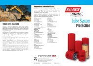
MPEB: Standard configuration, capacities and dimensionsTypeMPEB(Single system)MPEB-VT(Dividedsystem)MPEBDeoiler 2000(Dual system)ConfigurationFlow rate(m 3 /h)Size, including service spaceL × W × H (mm)Weight(kg)1.0 2500 × 1200 × 1400 5502.5 3000 × 1300 × 1800 6505.0 3400 × 1500 × 2000 100010.0 3400 × 1500 × 2000 1050First stageSecond stage0.25 1600 × 1000 × 1100 700 × 500 × 1400 2500.5 1600 × 1100 × 1300 700 × 500 × 1400 3001.0 2000 × 1200 × 1400 700 × 500 × 1800 3902.5 2600 × 1300 × 1800 1100 × 1000 × 1800 6305.0 3100 × 1700 × 2000 1200 × 1100 × 2200 103010.0 3100 × 1700 × 2000 1200 × 1100 × 2900 11700.25 1500 × 900 × 1150 4000.5 1600 × 1700 × 1300 5201.0 1600 × 2000 × 1500 6002.5 2700 × 2300 × 1800 9005.0 2800 × 2800 × 2000 125010.0 2800 × 2800 × 2000 1300ReferencesHundreds of MPEB unitsapproved according tothe latest IMO ResolutionMEPC.107(49) are nowinstalled on ships belongingto renowned ship -owners, many of whomare returning customerswho relied on previousgenerations of the system.System benefitsCompact, modular, flexible design. Threemo dels, two pump options and several differentsizes are available. Customisation is alsoavail able upon request.Easy to operate. Simply start the system andleave it running. By connecting the system toa level switch in the bilge <strong>water</strong> tank, theMPEB will auto matically start.No moving parts. The MPEB does not haveany moving parts and generally operates atambient temperature .Lower operating costs. The MPEB reducesoperating costs by eliminating the need forchemicals, absorption processes, membranefilters and backflushing.Technical support. All spares, service andsales engineers are available through aninternational service network.Standard sizesThe MPEB from <strong>MAHLE</strong> Industriefiltration isavailable in three models:MPEB: Single system, in one pressure vessel.MPEB-VT: Divided system, in two individualpressure vessels. Suitable for retrofit installations.MPEB Deoiler 2000: High-performance dualsystem, in two pressure vessels built together.Delivery optionsDifferent delivery options are offered:Built-on pump to facilitate installation.Separate feed pump to minimise suctionhead where required.9
What makes theMPEB a uniquelysimple concept?In addition to its simpleworking principle, it issimple to operate,simple to maintain,simple to install, and,simple to commission.Working principleThe MPEB continuously separates oil, emulsionsand dispersions from <strong>water</strong> without backflushingor the use of chemicals. However,because the MPEB has a self-cleaning function,it effectively overcomes the challenges ofusing absorption filters.The MPEB provides con tinuous pressure-type<strong>separation</strong> in two stages using the principles ofgravity and coalescence to separate oil andsolid particles from the bilge <strong>water</strong>.In the first stage, the NFV Multi-Phase Se pa r a -tor MPS uses patented profiles to separate oiland solids from the bilge <strong>water</strong>.In the second stage, the NFV Mechanical Emul -sion Breaker MESB separates fine emulsified oildroplets using patented emulsion breaker elements.Separated oil is discharged to a wasteoil tank. An oil-in-<strong>water</strong> monitor measures theresidual oil content before cleaned <strong>water</strong> is dischargedoverboard.A UNIQUELY SIMPLE CONCEPTTO COMPLY WITH THE MEPC.107(49) STANDARDMPS: Patented wave-typeprofiles of oleophilic materialare stacked one on topof the other. Ten to fifteenrows of profiles, dependingon separator size, areplaced in an insert.Microfibre bed element.The second stage consistsof between two andtwelve elements, dependingon the size of theseparator.1 st stage:NFV Multi-Phase Separator MPSThe helical rotary pump transfers the oily <strong>water</strong>mixture from the bilge <strong>water</strong> settling or collectingtank into the MPEB separator, where largeroil drops and solids are pre-separated by gravityand a good amount of oil instantly flowsupward into the oil collecting dome.After that, the oily <strong>water</strong> mixture flows throughthe patented Multi-Phase Separator MPS whe reit is led through a parallel arrangement of wavetypeprofiles (see figures for first stage on thelower left-hand side of page 9).Small droplets of the lighter discontinuousphase (oil) collect at the lower edges of the profilesdue to the combined effects of gravity, flowand coalescence. The small oil droplets coalesceto form larger droplets as they collectunderneath the profiles, where they float to thetop of the profiles, pass through the openingsand flow onward to the oil dome. As thedroplets rise, any solid particles that are suspendedin the droplets separate from the oildue to the difference in the densities betweenthe oil and the solids. The particles drop ontothe profile below, sliding off the profile edges tothe bottom of the separator, where they aredrained into the sludge tank.The oil collected in the oil dome during this firststage is automatically drained into the sludge/waste oil tank via the discharge valve, which isacti vated by a signal from the level electrodeloca ted in the oil dome.After passing through the Multi-Phase Sepa -rator, the oily <strong>water</strong> mixture is directed onwardto the Mechanical Emulsion Breaker, whichcomprises the second stage of the system.10
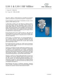
1 st stage 2 nd stage131. Screen effective2. Flow collision3. Interception4. Inerti al impaction24Small oil droplets collect at the lower edge of the profiles and coalesceinto larger droplets. These droplets flow upward into theoil dome, where it is collected and drained into the waste oil tank.Coalescing effects in the microfibre bed which consists of variouslayers of different types of micrometre thin fibres of a specialoleophilic material (a material that “loves” oil).2 nd stage:NFV Mechanical Emulsion Breaker MESBThe MESB processes the oily <strong>water</strong> from theMPS. This stage utilises pa ten ted EmulsionBrea ker elements to separate fine emulsified oildroplets which remain in the bilge <strong>water</strong> after thefirst stage of processing. The main principle of<strong>separation</strong> utilised in this stage is coalescence.In the microfibre bed, the <strong>separation</strong> of oil from<strong>water</strong> is possible even when the difference indensity between the two liquids is minute (seefigures for the second stage above).The oily <strong>water</strong> enters the Mechanical EmulsionBreaker through a perforated pipe and passesthrough a microfibre bed where the principlesof filtration, collision, interception and inertialimpaction contribute to the formation of largeroil droplets.The fine droplets of oil collect between the filamentsof the microfibre and form a wetting film.The oil proceeds along with the continuousphase (<strong>water</strong>) to the outer periphery of themicro fibre bed where the liquids pass through asleeve, which contributes to the formation oflarger drops of oil. The drops of oil rise intermittentlyupward and onward into the oil domeof this second stage. The oil collected in thesecond oil dome is automatically drained intosludge/waste oil tank via the discharge valve.The sampling point for the oil-in-<strong>water</strong> monitoris located in the clean <strong>water</strong> outlet of the secondstage. The <strong>separation</strong> result is continuouslymonitored. If the <strong>separation</strong> result is less thanor equal to 15 ppm, the cleaned <strong>water</strong> is directedfor discharge overboard. If the result isgreater than 15 ppm the bilge <strong>water</strong> is re-circulatedback to the bilge <strong>water</strong> tank.Operation andmaintenanceSimply start or stop thepump to operate the unit.As an option, the unitmay also be configured tooperate automatically byusing level switches inthe bilge holding tank tostart the pump.Maintenance is easy andconvenient. The NFV Multi-Phase Separator elements(first stage) must becleaned on occasion aboutonce a year, but noreplacement is necessary .NFV Mechanical EmulsionBreaker elements(second stage) requirereplacement when thedif fer ential pressurereaches the set point orabout every two years.11
SIGNIFICANT ADVANTAGESMPEB VERSUS CONVENTIONAL TECHNOLOGIESCross section ofabsorption elements:New (above) and after2.5 hour emulsion testaccor ding to IMOpro ce dures (beyond).Conventional gravity (static) oil separators onboard most vessels sailing the oceans todayare unable to meet the requirements of the IMOReso lu tion MEPC.107(49). These systems weredesigned to handle the requirements for efficient<strong>separation</strong> under the IMO ResolutionMEPC.60(33) which went into effect in 1993.For systems to be approved according toMEPC.60(33) the systems were tested with differentmixtures of oil and <strong>water</strong>. These simplegravity separators have difficulties in manycases when confronted with the emulsifiedbilge <strong>water</strong> that is often produced on board.That’s why the new MEPC.107(49) specifiesthat bilge <strong>water</strong> separators must also be testedwith an emulsion. The test emulsion is composedof a mixture of <strong>water</strong>, heavy fuel oil, gasoil, tensides and fine iron oxide particles.To fulfil the new rules most bilge <strong>water</strong> systemsnow have added a second stage downstreamin order to meet the requirements of handlingemulsions and dispersions according toMEPC.107(49). This second stage is of differenttypes:Absorption filtersMany suppliers have added absorption filtersafter the gravity oil separators in order to meetMEPC.107(49) requirements. These inline ab -sorp tion filters are sometimes designed to lastnot much more than the 2.5 hour duration ofthe IMO MEPC.107(49) test for the handling ofemulsions and dispersions. For example, for a2.5 m 3 /h system of 27 kg of oil must beabsorbed during the 2.5 hours if 50 percent ofthe emulsified oil is to be taken up in theabsorption stage.If the absorption filters are optimised in this wayfor the 2.5 hour IMO test, the filters then quicklytend to reach their design capacity, becomesaturated and require immediate replacement.However, because the composition of bilge<strong>water</strong> varies, there isn’t any scientific way toan ti cipate when the initial breakthrough of oilmay occur. An alarm triggered by the oil-in<strong>water</strong>monitor is the first indication to the operatorthat something is wrong.This means that the service life of the filter willbe short under actual operating conditions,12
Comparison with conventional technologiesPrinciple of other make Comment MPEBSuction-type system Often requires a second pump before the system due to limited Pressure-type systempump suction height.Requires the bilge separator and the bilge <strong>water</strong> holding tank to beclose to or at the same level.Backflushing systems Requires the interruption for cleaning with fresh <strong>water</strong>. Continuous operationGenerates a lot of waste oil with high <strong>water</strong> content, and thus highand no backflushingwaste disposal costs.requiredLowers actual capacity to less than that of nominal capacity.ChemicalsAbsorption filterActive carbon bedCreates waste by contributing approximately 15 to 25 percent ofthe content of bilge <strong>water</strong> that requires disposal on shore.Requires frequent replacement before the filter reaches its saturationpoint, thus increasing operating costs.Can cause oil to be released into the system if the filter is notreplaced before reaching its saturation point.Does not provide an adequate filtering effect since active carbonbeds are primarily used to purify drinking <strong>water</strong> systems and not tofilter oil from waste<strong>water</strong>.Requires feed to contain less than 10 to 20 ppm to obtain acceptableproduct life cycle.Is sensitive to solids.Requires frequent replacement and disposal.Is labour intensive, requiring more man hours for maintenance.No chemicalsrequiredNo absorption filterrequiredNo active carbon bedrequiredeven if real bilge <strong>water</strong> rarely has the amount ofemulsions and dispersions as the bilge <strong>water</strong>used for the IMO test.Whatever the interval, the filter elements mayrequire frequent re place ment, which in the caseof activated carbon filters is a dirty process thatrequires special handling and disposal whichcan be expensive.BackflushingMost conventional gravity oil separators useintermittent backflushing sequences to cleanthe system. Intermittent backflushing, however,reduces the nominal capacity of the separatorbecause it requires <strong>water</strong> for cleaning to bepumped at designated intervals into the system.ChemicalsAnother solution for a second stage downstreamis the addition of a chemical <strong>separation</strong>plant and additional filters filled with sand,granulate and/or activated carbon. This solution,however, is a costly, labour-intensive alternativethat generates a lot of waste. Between15 and 25 percent of the treated bilge <strong>water</strong>must be pumped ashore, which is an expensivepro cess in many ports, and sent to a landbasedplant for further processing.Typical layout of conventionalsuction coalescerwith absorption filter suppliedby other manufacturers.The backflushing <strong>water</strong> may contain be tween70 and 80 percent waste oil. Back flushingincreases the overall consumption of <strong>water</strong> onboard. It also increases the volume of <strong>water</strong>that is discharged to the waste oil tank, thusgenerating an increased volume of sludge foronshore disposal.13
MPEB-VT 5SIMPLE, COMPACT DESIGNFOR THE BEST USE OF AVAILABLE SPACEThe MPEB bilge <strong>water</strong> separators are availablein different designs, sizes and capacities. Thisenables flexibility in both design and configurationto enable shipbuilding companies to implementeffective, creative solutions.1 st stage:NFV Multi-Phase Separator MPSThe Multi-Phase Separator consists of an insertwith patented wave-type profiles for the <strong>separation</strong>of oil and solid particles from the bilge<strong>water</strong> and a pump, heater and oil dome to collectseparated oil.The Multi-Phase Separator also has the followingauxiliary parts:Automatic oil drain with level electrode andpneumatic operated oil discharge valve,Control cock at the oil collection dome,Safety valve,Pressure gauge, and,Solenoid valve for scavenger line.2 nd stage:NFV Mechanical Emulsion Breaker MESBThe Mechanical Emulsion Breaker consists of achamber with patented emulsion breaker elementsfor the <strong>separation</strong> of fine emulsified oildroplets and a pump, heater and oil dome tocollect separated oil.The Mechanical Emulsion Breaker has the followingauxiliary parts:Automatic oil drain with level electrode andpneumatic operated oil discharge valve,Control cock at the oil collection dome,Differential pressure switch with electric contacts,Pressure gauge,Solenoid valve for scavenger line,Spring loaded non-return valve,Pneumatically operated three-way valve in theoutlet to re-circulate separated bilge wa ter ifresidual oil content exceeds 15 ppm, and,Manual three-way valve for harbour test.14
Key componentsDry-run pump protectionFor built-on pumps: The level electrodes in theoil domes cause both the oil discharge valve andthe solenoid valve of the scavenger line that isaffected to open for a pre-set interval. The scavengerline serves as the source of priming fluid.If the pre-set interval is exceeded, the pumpautomatically shuts off and an alarm is activated.For pumps installed separately: An electronicDry Running Protection Device (TSE) uses atemperature sensor installed in the pump statorto provide protection. When the pump runs dry,the valve in the suction line automatically closesand the scavenger line transfers primingfluid (in this case, bilge <strong>water</strong>) out of the MPEBand into the pump.Patented insertsStacked in the Multi-Phase Separator, wavelikeprofiles employ the principles of gravity andcoalescence to separate the oil and particlesfrom the <strong>water</strong>.Micro-fibre bedA micro-fibre bed in the Mechanical EmulsionBreaker use the principles of filtration, collision,interception, inertial impaction and coalescenceto remove any emulsions which remainafter the first processing stage.Oil domesThe MPEB has two oil domes, one in the Multi-Phase Separator and one in the MechanicalEmulsion Breaker. Each dome collects the oilthat is separated from the bilge <strong>water</strong> duringeach stage of <strong>separation</strong>.Control cocksControl cocks are situated on the oil domes tocheck the function of the level electrodes.Oil drainsOil drains are situated in both processingstages. The level electrodes in each oil domeautomatically control the drainage intervals.When the oil level reaches its maximum capa -city, the level electrodes signal the control unit,which opens a valve to release the oil that hasaccumulated in the dome into the waste oiltank. Manual operation is also possible.Sludge drainsSludge drains are located at the bottom of each<strong>separation</strong> chamber to transfer sludge collectedduring the <strong>separation</strong> process to the sludgetank of the ship.Differential pressure switchA differential pressure switch monitors thepres sure drop across the microfibre bed elementsin the second stage. If the differentialpressure exceeds the maximum allowable va -lue, the unit automatically switches off and thecontrol cabinet indicates that the elementsmust be replaced.Control cabinetMounted directly on the MPEB, the controlcabinet houses the main switch, pump switch,hour meter and pro cess controller, which providesautomatic operation and supervision. Theprocess controller makes the unit easy to operate,providing fully automated monitoring andcontrol of all system functions.Oil-in-<strong>water</strong> monitorThis OMD 2005 type monitor continuouslyanalyses the cleaned bilge <strong>water</strong> using samplesthat are extracted through the <strong>water</strong> line situatedat the outlet. When the residual oil contentis 15 ppm or less, the cleaned <strong>water</strong> passesthrough the three-way valve for immediate dischargeoverboard or is routed to holding tankfor discharge later. When the residual oil contentexceeds the 15 ppm limit, the three-wayvalve re-circulates the <strong>water</strong> to the bilge <strong>water</strong>tank for re-processing.Harbour control valveWhen the ship is in port, bilge <strong>water</strong> separatorscan undergo inspection by authorities. To facilitateinspection, a manually operated three-wayvalve is installed immediately after and adjacentto the three-way valve on the outlet. Thisenables authorities to test the bilge alarm andthe automatic stopping device without dischargingany bilge <strong>water</strong> overboard.Oil-in-<strong>water</strong> monitorHelical rotary pumpThis progressive cavitypump transfers oily <strong>water</strong>from the bilge tank intothe MPEB. The specialdesign of the rotor andstator minimises agitation,thus reducing theformation of emulsions.The pump may be builton to the MPEB or deliveredas a separate unit.15
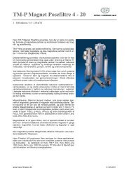
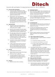
Flow diagram1Helical rotary pumpTransfers bilge <strong>water</strong> to the bilge sepa -rator.5Oil domesCollect oil that is separated from the bilge<strong>water</strong>.23Strainer (Not included)Traps large particles from the bilge <strong>water</strong>be fore the fluid enters the bilge sepa -rator .Electric heaterHeats the oil to prevent clogging by hea -vy fuel oil when the unit is not in operation.67Oil drainsAutomatically discharge oil that collectsin the dome to the waste oil tank.Level electrodesMeasures the level of oil in the dome attwo different levels and opens the oildrain valve for inter mittent discharge ofoil and air that have accumulated.4Multi-Phase Separator (1 st stage)Separates oil from bilge <strong>water</strong> usingpatented profiles and the force of gravity.8Safety valveAutomatically releases pressure in theunit, when pressure exceeds 3.8 bar.Flushing <strong>water</strong>To waste oil tank8LS7 6351From drainsand leaks4Frombilge wells213 13<strong>Bilge</strong>holdingtankSludgedrain
91011Solenoid valve for scavenger lineEnables the passage of <strong>water</strong> into thepump in order to prevent dry-running ofthe pump.Mechanical Emulsion Breaker(2 nd stage)Separates fine emulsions using patentedmicrofibre bed to agglomerate fine oildroplets into a wetting film.Differential pressure switchAutomatically switches the unit off if thepressure drop exceeds 1.5 bar, and indicateson the control cabinet when elementsrequire replacement.13141516Sludge drainsDischarge collected sludge and particlesto sludge tank.Control cabinetAutomatically controls bilge <strong>water</strong> separatorfunctions and starts the pumps.Oil-in-<strong>water</strong> monitorContinuously measures oil content ofcleaned bilge <strong>water</strong>.Three-way valveDischarges clean <strong>water</strong> overboard andre-circulates oily <strong>water</strong> that exceeds the15 ppm limit to the bilge <strong>water</strong> tank.12Spring-loaded non-return valveDirects the cleaned <strong>water</strong> overboard.Spring loaded at 0.7 bar in the outlet.17Harbour control valveEnables manual testing of the bilge <strong>water</strong>separator while the ship is in port.1415Sampling <strong>water</strong>6LS7119PDS5912161031317Cleaned <strong>water</strong>overboard
Benefits for shipyardsPre-mounted system for easy installation.Complete delivery, including harbour controlvalve, dry-run protection and overboard nonreturnvalve.Easy commissioning and initial start-up.Flexible configuration for different engineroom designs.Benefits for shipownersReliable, easy-to-operate system providescontinuous operation with automated controland monitoring system.High <strong>separation</strong> efficiency, thanks to the pa -ten ted profiles and emulsion breaker elements.Reduced operating costs, thanks to automatedcontrol, low maintenance and minimalfresh <strong>water</strong> consumption.TREATMENT OF OILYMPEB 5MPEB-VT 5RetrofittingMPEB is ideal for replacing older bilge <strong>water</strong> se -parator systems. It is available as the MPEB-VT,which is a separator unit that consists of twovessels. The first vessel is placed in the samelocation as the old bilge <strong>water</strong> separator; thesecond vessel may be placed anywhere in theengine room where there is any available space.ApprovalThe MPEB and the oil-in-<strong>water</strong> monitor areapproved according to the IMO ResolutionMEPC.107(49) as well as the European MarineEquipment Directive, MED 2002/75/EC.Documentation<strong>MAHLE</strong> Industriefiltration supplies each MPEBbilge <strong>water</strong> separator with full documentationeither as paper copies or as PDF (Portable Do -cu ment Format) files on a CD-ROM. The ins t r -uct ion manual, which can also be made availablein most major languages, covers:SafetySystem descriptionOperating instructionAlarms and fault findingInstallation instructionsSpare partsComponent descriptionsThe MPEB also fulfils the requirements of allmajor classification societies. Upon request,the MPEB can be delivered with individual testcertificates (USCG-certificate No.162.050/9041/0or RMRS-certificate No. 06.001.08.272).Spare parts, service and support<strong>MAHLE</strong> Industriefiltation provides spare partskits for all service and maintenance needs. Glo -bal technical service, training and support areavailable throughout the lifetime of the MPEB.18
WASTE WATERON BOARD SHIPS
<strong>MAHLE</strong> Industriefiltration GmbHPlant HamburgTarpenring 31–33D-22419 HamburgPhone +49 (0) 40-53 00 40-0Fax +49 (0) 40-52 76-567mahle.nfv@mahle.comwww.mahle-industrialfiltration.com<strong>MAHLE</strong> Filtersysteme GmbHIndustriefiltrationSchleifbachweg 45D-74613 ÖhringenPhone +49 (0) 79 41-67-0Fax +49 (0) 79 41-67-234 29industriefiltration@mahle.comwww.mahle-industrialfiltration.com70370376.07/2008 www.mahle-industrialfiltration.com