Synchronous Generators BG 132 and BG 160 - gts generator ...
Synchronous Generators BG 132 and BG 160 - gts generator ...
Synchronous Generators BG 132 and BG 160 - gts generator ...
- No tags were found...

You also want an ePaper? Increase the reach of your titles
YUMPU automatically turns print PDFs into web optimized ePapers that Google loves.
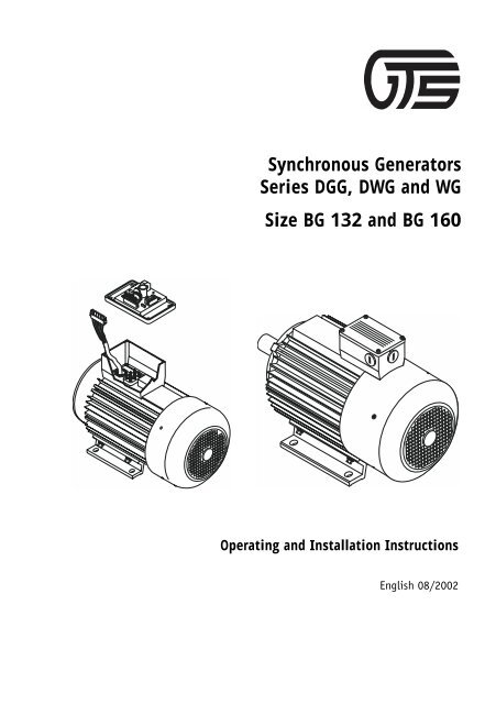
<strong>Synchronous</strong> <strong>Generators</strong>Series DGG, DWG <strong>and</strong> WGSize <strong>BG</strong> <strong>132</strong> <strong>and</strong> <strong>BG</strong> <strong>160</strong>Operating <strong>and</strong> Installation InstructionsEnglish 08/2002
<strong>Synchronous</strong> <strong>Generators</strong> <strong>BG</strong> <strong>132</strong> / <strong>BG</strong> <strong>160</strong>Copyright, general information, manufacturer's addressCopyrightNo part of this Operation Manual may be reproduced, published or transmitted inany form or by any means without the express permission of Generator-TechnikSchwäbisch Gmünd GmbH &Co. KG.© 2002 Generator-Technik Schwäbisch Gmünd GmbH & Co. KG. All rightsreserved.General informationTechnical modifications after date of printing are not considered. Subject tochange without notice.Issue date: August 2002Validity of the manualThis manual applies to all synchronous <strong>generator</strong>s of the types DGG (three-phaseDC <strong>generator</strong>s), DWG (three-phase AC <strong>generator</strong>s) <strong>and</strong> WG (single-phase AC<strong>generator</strong>s). However, for reasons of clarity only three-phase AC <strong>generator</strong>s arerepresented <strong>and</strong> mentioned in the manual. In their general sense the givenexplanations are however also applicable for single-phase AC <strong>generator</strong>s of theseries WG <strong>and</strong> appropriate <strong>generator</strong>s with special voltages <strong>and</strong> frequencies.Further information about the designation system for the various <strong>generator</strong> typescan be found in chapter 1 on page 11.Manufacturer's addressFor any information <strong>and</strong> support concerning technical problems, services <strong>and</strong>orders please contact us.Generator-Technik Schwäbisch Gmünd GmbH & Co. KGZiegelfeldstraße 18D-73563 Mögglingen, GermanyPhone +49 7174 89 80 0 0Fax +49 7174 89 80 0 252 Issue date: August 2002
<strong>Synchronous</strong> <strong>Generators</strong> <strong>BG</strong> <strong>132</strong> / <strong>BG</strong> <strong>160</strong>Table of contentsTable of contentsSome important <strong>and</strong> valuable information .................................................. 5Warranty ............................................................................................... 5Proper use ............................................................................................ 6Preconditions <strong>and</strong> requirements to be met by the place of installation ........... 6Safety precautions ................................................................................. 71 Designation system for <strong>generator</strong> types .............................................. 111.1 Type codes .............................................................................. 111.2 Examples for designations .......................................................... 122 Description .................................................................................... <strong>132</strong>.1 Use of different sizes (<strong>BG</strong> <strong>132</strong> <strong>and</strong> <strong>BG</strong> <strong>160</strong>) .................................. <strong>132</strong>.2 Overview of features <strong>and</strong> options for different sizes <strong>and</strong> designs ...... <strong>132</strong>.3 General functionality ................................................................ 152.4 Generator governor ................................................................... 172.5 Mechanical designs ................................................................... 192.6 Drive types .............................................................................. 212.7 Terminal box (st<strong>and</strong>ard version) .................................................. 222.8 Control box (optional, only for 8 kVA <strong>and</strong> 13 kVA <strong>generator</strong>s) .......... 233 Technical data ................................................................................ 253.1 <strong>Generators</strong> ............................................................................... 253.2 Control box (optional, only for 8 kVA <strong>and</strong> 13 kVA <strong>generator</strong>s) .......... 253.3 Generator governor ................................................................... 254 Installation .................................................................................... 274.1 Safety precautions for installation ............................................... 274.2 Requirements to be met by the place of installation <strong>and</strong> use ........... 294.3 General regulations for installation ............................................. 294.4 Permissible mounting positions <strong>and</strong> drain holes for cond. water ....... 314.5 Installation for single-bearing <strong>generator</strong>s ..................................... 35Issue date: August 2002 3
<strong>Synchronous</strong> <strong>Generators</strong> <strong>BG</strong> <strong>132</strong> / <strong>BG</strong> <strong>160</strong>Table of contents4.6 Installation of two-bearing <strong>generator</strong>s (<strong>BG</strong> <strong>132</strong>) ........................... 494.7 Installation of two-bearing <strong>generator</strong>s (<strong>BG</strong> <strong>160</strong>) ........................... 624.8 Electrical connection of the <strong>generator</strong>s ........................................ 705 Operation ...................................................................................... 735.1 Safety information for operation ................................................. 735.2 Permissible operating conditions ................................................ 755.3 Electric protection equipment, protective measures <strong>and</strong> grounding ... 755.4 Connection to an existing power distribution network(e.g. house wiring) ................................................................... 775.5 Operating information for safe working with electric devices ........... 785.6 Operation of the <strong>generator</strong> ......................................................... 806 Maintenance .................................................................................. 856.1 Maintenance overview ............................................................... 866.2 Safety precautions .................................................................... 876.3 Visual inspections <strong>and</strong> cleaning to be performed by the user ........... 886.4 Maintenance to be performed by authorized qualified personnel ...... 897 Reconditioning ............................................................................... 928 Removal ........................................................................................ 938.1 Safety precautions .................................................................... 938.2 Removal of two-bearing <strong>generator</strong>s (<strong>BG</strong><strong>132</strong> <strong>and</strong> <strong>BG</strong><strong>160</strong>) ................. 938.3 Removal of single-bearing <strong>generator</strong>s .......................................... 939 Transport <strong>and</strong> storage .....................................................................10310 Putting out of operation, storage after dismantling, disposal ................10410.1 Waste disposal information .......................................................10411 Spare parts ...................................................................................1054 Issue date: August 2002
<strong>Synchronous</strong> <strong>Generators</strong> <strong>BG</strong> <strong>132</strong> / <strong>BG</strong> <strong>160</strong>Some important <strong>and</strong> valuable informationSome important <strong>and</strong> valuable informationDear customer,Generator-Technik Schwäbisch Gmünd GmbH & Co. KG is a technically leadingmanufacturer of power <strong>generator</strong>s in the best tradition <strong>and</strong> manufactures<strong>generator</strong>s with ratings of 4 to 30 kVA as well as its own design of electroniccontrol units for those <strong>generator</strong>s. What makes GTS <strong>generator</strong>s st<strong>and</strong> out is theirexcellent fitness for practical use <strong>and</strong> superior quality. They are maintenancefree,durable, precise <strong>and</strong> robust.Choosing a synchronous <strong>generator</strong> of this series was a decision for a technicallysuperior product. This product has been manufactured using only high-qualitycomponents which meet the requirements of VDE testing <strong>and</strong> comply withappropriate German (DIN) <strong>and</strong> European (EN) st<strong>and</strong>ards.All information contained in these operating instructions has been carefullycompiled <strong>and</strong> checked by us to the best of our knowledge <strong>and</strong> belief. Please besure to read <strong>and</strong> underst<strong>and</strong> the operating instructions before installing,commissioning <strong>and</strong> using the <strong>generator</strong>.Generator-Technik Schwäbisch Gmünd GmbH & Co. KG does not assume anyliability for any applications which are contrary to the descriptions given inthese operating instructions, <strong>and</strong> for any loss or damage which has been causedby incorrect operation <strong>and</strong> h<strong>and</strong>ling, faulty installation, improper use, abuse,non-approved technical modifications or by any repairs performed byunauthorized personnel.If you have any questions, please contact Generator-Technik Schwäbisch GmündGmbH & Co. KG.WarrantyYours sincerely,Generator-Technik Schwäbisch Gmünd GmbH & Co. KGFor the <strong>generator</strong>s of the series described in this manual, we issue warrantyaccording to the latest version of the "Allgemeine Lieferbedingungen fürErzeugnisse und Leistungen der Elektroindustrie (general conditions for thesupply of products <strong>and</strong> services of the electrical industry)" of the ZVEI.Issue date: August 2002 5
<strong>Synchronous</strong> <strong>Generators</strong> <strong>BG</strong> <strong>132</strong> / <strong>BG</strong> <strong>160</strong>Proper useProper useThe <strong>generator</strong>s described in this manual are intended for the generation ofelectrical energy within the context of emergency st<strong>and</strong>by operation for feedingin mobile distribution systems. The <strong>generator</strong>s must only be used according tothe voltage <strong>and</strong> power specifications listed on the type plate. Reverse feedingoperation (e.g. connection of four-quadrant converters) is not planned <strong>and</strong> onlyconditionally possible after consulting the manufacturer.The <strong>generator</strong>s have to be driven with the specified rated speed. The <strong>generator</strong>outputs have to be protected against overcurrent <strong>and</strong> short-circuit by adequatefuse equipment according to the specifications on the type plate.The <strong>generator</strong>s must not be connected to other power distribution or electricitygeneration systems (such as other <strong>generator</strong>s or the public electricity supplynetwork, for example).The use of the <strong>generator</strong>s is only allowed for applications described here <strong>and</strong> inconformity with the specifications given in this manual. Any other application isconsidered to be improper use <strong>and</strong> is not permitted.In case of improper use, misuse or abuse of the <strong>generator</strong>s or of parts of them,Generator-Technik Schwäbisch Gmünd GmbH & Co. KG will not assume anyliability.Preconditions <strong>and</strong> requirements to be met by the place ofinstallationSingle-bearing <strong>generator</strong>s are mounted directly to the engine. These <strong>generator</strong>smay only be mounted to engines which comply with the applicable regulations,rules <strong>and</strong> requirements.Two-bearing <strong>generator</strong>s are usually installed right next to the engine. The<strong>generator</strong> has to be firmly <strong>and</strong> securely mounted on an absolutely flat base witha bearing capacity adequate to the weight class of the <strong>generator</strong>. When using abelt drive, it is advisable to mount the <strong>generator</strong> adjustable. For that purposee.g. mounting rails can be used, providing the possibility of adjusting the belttension.All <strong>generator</strong>s are splash-proof according to IP54 specifications <strong>and</strong> can thusalso be mounted <strong>and</strong> used outdoor. The <strong>generator</strong>s are not explosion-protected<strong>and</strong> thus must no be used in explosive atmospheres. Further regulations on thishave to be observed!6 Issue date: August 2002
<strong>Synchronous</strong> <strong>Generators</strong> <strong>BG</strong> <strong>132</strong> / <strong>BG</strong> <strong>160</strong>Safety precautionsWhen selecting the place of installation <strong>and</strong> use, the required minimumclearances have to be observed, adequate ventilation has to be ensured at anytime, <strong>and</strong> the temperature of the cooling air must not exceed 40 °C. Furtherinformation can be found in chapter 4 on page 27.The <strong>generator</strong>s <strong>and</strong> the parts mounted to them must not be sprayed with highpressurecleaners. Therefore, the <strong>generator</strong>s should preferably be installed in away <strong>and</strong> place which makes it impossible to even inadvertently spray the<strong>generator</strong> with high-pressure cleaners.Safety precautionsThis section summarizes the safety precautions of relevance. Read <strong>and</strong>underst<strong>and</strong> the safety precautions before installing, commissioning <strong>and</strong>operating the <strong>generator</strong> <strong>and</strong> observe the precautions. You will find the safetyprecautions in the relevant passages through the manual as well.Work on electrical installations <strong>and</strong> equipment may only beperformed by adequately trained qualified personnel <strong>and</strong> inconformity with the applicable national rules <strong>and</strong> regulations(in Germany: VDE regulations, among others).DANGERRisk ofpersonal injuryor death<strong>and</strong>destructionhazardWork on electrical installations <strong>and</strong> equipment may only beperformed in the off <strong>and</strong> de-energized state. Mortal danger byelectric shock! Engines that have been turned off must besecured against accidental restarting (e.g. by removing theignition key <strong>and</strong> keeping it safe)!Installation <strong>and</strong> commissioning of the <strong>generator</strong> as well as anymaintenance, service <strong>and</strong> replacement work may only beperformed by authorized <strong>and</strong> qualified personnel.Do not operate the <strong>generator</strong> in explosive environments.Further regulations on this have to be observed!Do not perform any visual inspections for maintenancepurposes <strong>and</strong> cleaning work on the <strong>generator</strong> during operation.Always turn off the engine first <strong>and</strong> make sure that it cannot berestarted accidentally (e.g. by removing the ignition key <strong>and</strong>keeping it safe). Mortal danger by electric shock!Issue date: August 2002 7
<strong>Synchronous</strong> <strong>Generators</strong> <strong>BG</strong> <strong>132</strong> / <strong>BG</strong> <strong>160</strong>Safety precautionsDANGERRisk ofpersonal injuryor death<strong>and</strong>destructionhazardNever connect the <strong>generator</strong> to the public electricity supplynetwork or to any other systems for power generation. Risk ofdeath, fire <strong>and</strong> destruction hazard!Never connect several <strong>generator</strong>s to each other. Risk of death,fire <strong>and</strong> destruction hazard!If the <strong>generator</strong> shall be connected to an existing powerdistribution network (e.g. a house wiring), it has to beensured, that the system is completely <strong>and</strong> reliablydisconnected from the public electricity supply network of theenergy supply company. Reverse feeding into the publicelectricity supply network or network interconnection is notallowed. Reverse feeding involves mortal danger by electricshock for persons possibly working at the de-energized publicelectricity supply network. Due to network interconnectionwith the public electricity supply network, the <strong>generator</strong> can bedamaged, burn or cause fire in electrical cables of the system.Grounding the neutral conductor of the <strong>generator</strong> (N, midpointconductor) supersedes the protective measure "protectionseparation" <strong>and</strong> should therefore be avoided. If the neutralconductor N shall be grounded anyway, this may only beperformed by an electrically qualified person. In this case, acurrent-operated earth-leakage circuit breaker has to beconnected on the load side of the <strong>generator</strong> output. Theefficiency of the electrical protective measure has to beconfirmed by an appropriate measurement.The <strong>generator</strong> supplies highly dangerous voltages duringoperation! Never touch the <strong>generator</strong> or the devices connectedto the <strong>generator</strong> with wet h<strong>and</strong>s during operation. Mortaldanger by electric shock!Generator components may be very hot, not just during but alsoafter operation. Burning hazard!The <strong>generator</strong> may only be operated with the protective coversfor the drive mounted as specified. Risk of personal injury!8 Issue date: August 2002
<strong>Synchronous</strong> <strong>Generators</strong> <strong>BG</strong> <strong>132</strong> / <strong>BG</strong> <strong>160</strong>Safety precautionsBe sure to read <strong>and</strong> underst<strong>and</strong> the operating instructionscompletely before using the <strong>generator</strong>. The <strong>generator</strong> may onlybe used for applications described in section "Proper use"above <strong>and</strong> in conformity with the specifications in this manual.DANGERRisk ofpersonal injuryor death<strong>and</strong>destructionhazardBefore connecting devices to the <strong>generator</strong>, ensure that thedevices are switched off. Accident hazard! Unsupervisedstarting devices can endanger or injure persons as well as causedamages or damage themselves.Infants <strong>and</strong> animals must never have admittance to the<strong>generator</strong>, not just during but also after operation. Makeappropriate precautions. Mortal danger by electric shock, injury<strong>and</strong> burning hazard!The <strong>generator</strong> or its components must never beexposed to the jet of high-pressure cleaners.Mortal danger by electric shock <strong>and</strong>destruction hazard!CAUTIONDestructionhazardordamageBe sure to observe the permissible operating conditions given insection 5.2 on page 75. The <strong>generator</strong> may only be operated inconformity with the operating conditions <strong>and</strong> data specified there.This particularly applies to the ambient <strong>and</strong> cooling conditions <strong>and</strong>the permissible current load.For installation <strong>and</strong> repair only genuine components or externalcomponents expressly approved by the manufacturer may be used.It is not permitted to perform any modifications on the <strong>generator</strong>or on individual components or the control box. Any modification,improper repair or use of unsuitable external components willterminate all <strong>and</strong> any claims under a warranty as well as the typeapproval according to the German Equipment Safety Law <strong>and</strong> thecertification to EU / EEC directives. In this case the manufacturerwill not assume any liability.Issue date: August 2002 9
<strong>Synchronous</strong> <strong>Generators</strong> <strong>BG</strong> <strong>132</strong> / <strong>BG</strong> <strong>160</strong>Safety precautions10 Issue date: August 2002
<strong>Synchronous</strong> <strong>Generators</strong> <strong>BG</strong> <strong>132</strong> / <strong>BG</strong> <strong>160</strong>Chapter 1, Designation system for <strong>generator</strong> types1 Designation system for <strong>generator</strong> typesThis chapter provides information about the designation system for theindividual <strong>generator</strong> types as well as examples of <strong>generator</strong> designations.1.1 Type codesDWG (BL) 17 / 7,0 - 2ZEE: Electronic <strong>generator</strong> governorZ: Two-bearing designE: Single-bearing designNumber of poles:2 poles (rated speed 3000 rpm)or4 poles (rated speed 1500 rpm)Single-phase output power in kVA, e.g. 7 kVAThree-phase output power in kVA, e.g. 17 kVA.Power determines size:• 2-pole <strong>generator</strong>: up to 17 kVA = <strong>BG</strong> <strong>132</strong>,20 kVA <strong>and</strong> higher = <strong>BG</strong> <strong>160</strong>• 4-pole <strong>generator</strong>: 10 kVA <strong>and</strong> higher = <strong>BG</strong> <strong>160</strong>With specification (BL): Brushless <strong>generator</strong>Without specification (BL): Brush-type <strong>generator</strong>DWG: Three-phase AC <strong>generator</strong>WG: Single-phase AC <strong>generator</strong>DGG: Three-phase DC <strong>generator</strong>Issue date: August 2002 11
<strong>Synchronous</strong> <strong>Generators</strong> <strong>BG</strong> <strong>132</strong> / <strong>BG</strong> <strong>160</strong>Chapter 1, Designation system for <strong>generator</strong> types1.2 Examples for designationsTypeDWG 8,0/5,0-2EEFeaturesThree-phase AC <strong>generator</strong>, brush-type machine, 8 kVAthree-phase power, 5 kVA single-phase power, 2-polemachine, single-bearing design, electronic governor, size<strong>BG</strong> <strong>132</strong> (2-pole <strong>generator</strong> < 17 kVA).DWG (BL) 10/6-4ZE Three-phase AC <strong>generator</strong>, brushless, 10 kVA three-phasepower, 6 kVA single-phase power, 4-pole machine, twobearingdesign, electronic governor, size <strong>BG</strong> <strong>160</strong> (10 kVA,4-pole <strong>generator</strong>).12 Issue date: August 2002
<strong>Synchronous</strong> <strong>Generators</strong> <strong>BG</strong> <strong>132</strong> / <strong>BG</strong> <strong>160</strong>Chapter 2, Description2 Description2.1 Use of different sizes (<strong>BG</strong> <strong>132</strong> <strong>and</strong> <strong>BG</strong> <strong>160</strong>)Depending on the rated output power <strong>and</strong> the number of poles the <strong>generator</strong>sare produced in two different sizes: <strong>BG</strong> <strong>132</strong> or <strong>BG</strong> <strong>160</strong>.<strong>BG</strong> <strong>132</strong>Size <strong>BG</strong> <strong>132</strong> is used for• 2-pole <strong>generator</strong>s (driving speed 3000 rpm) with rated power outputs smallerthan 17 kVA.<strong>BG</strong> <strong>160</strong>Size <strong>BG</strong> <strong>160</strong> is used for• 2-pole <strong>generator</strong>s (driving speed 3000 rpm) with rated power outputs greaterthan <strong>and</strong> including 20 kVA or• 4-pole <strong>generator</strong>s (driving speed 1500 rpm) with rated power outputs greaterthan <strong>and</strong> including 10 kVA.2.2 Overview of features <strong>and</strong> options for different sizes <strong>and</strong>designsThe following table shows an overview of features <strong>and</strong> possible options for thedifferent <strong>generator</strong> sizes <strong>and</strong> types.Key for the table:x = possible or "yes"- = not possible or "no"Issue date: August 2002 13
<strong>Synchronous</strong> <strong>Generators</strong> <strong>BG</strong> <strong>132</strong> / <strong>BG</strong> <strong>160</strong>Chapter 2, DescriptionVersion / Option <strong>BG</strong> <strong>132</strong>2-pole up to17 kVAGenerator directly mounted toengineEngine-/manufacturer-dependingsealing betw. engine <strong>and</strong> <strong>generator</strong><strong>BG</strong> <strong>160</strong>2-pole ≥ 20 kVA4-pole ≥ 10 kVA1-bear. 2-bear. 2-bearingx - -x - -Direct coupling via flange - x xBelt or hydraulic drive - x xBrushless Generator x x xBrush-type <strong>generator</strong> x x -Supply without terminal box,cable directly lead out in a hoseTerminal box mounted,no governor/filter functionsTerminal box mounted,governor/filter functions partlyimplementedTerminal box mounted,governor/filter functions completelyimplementedOption "Exp<strong>and</strong>ed <strong>generator</strong>governor with no-load automatic"Control box mounted,aluminum cast or sheet metalx x xx x xx x xx x xx x xx 1 x 1 -Option hour meter in control box x 1 x 1 -Option insulation monitoring incontrol boxx 1 x 1 -1. Only available for versions with rated power output of 8 kVA or 13 kVA.14 Issue date: August 2002
<strong>Synchronous</strong> <strong>Generators</strong> <strong>BG</strong> <strong>132</strong> / <strong>BG</strong> <strong>160</strong>Chapter 2, Description2.3 General functionalityAll <strong>generator</strong>s of these series are self-excited synchronous inner-pole <strong>generator</strong>s.The <strong>generator</strong> consists of the functional groups main machine, exciter <strong>and</strong>rotating rectifier mounted in a common housing. The electronic <strong>generator</strong>governor can be placed in a terminal box mounted on the <strong>generator</strong>, an externalcontrol box or in the optional control box mounted on the <strong>generator</strong> instead ofthe terminal box.Due to various constructional measures, an amortisseur <strong>and</strong> a balancing controlthe <strong>generator</strong>s have an extreme asymmetric load capability.Cooling of the <strong>generator</strong>s is performed by a rotating direction-independent selfventilation.For this purpose, the cooling air is sucked on the rear side by a fanimpeller <strong>and</strong> then blown to the front outside along the <strong>generator</strong>.The supplied <strong>generator</strong> voltage is regulated by the electronic <strong>generator</strong> governor,so that the output voltage fulfills the requirements of IEC 38 for the entire rangebetween no-load <strong>and</strong> rated load condition. This corresponds to the qualityst<strong>and</strong>ard of the public electricity supply network. The output frequencyconstancy depends on the speed constancy of the engine.In case of short <strong>generator</strong> overload conditions (below the reaction time of thecircuit breakers) or if devices with a too high power consumption or a too highstarting power are connected to the <strong>generator</strong>, the <strong>generator</strong> governorautomatically limits the output power (by limiting the exciter field current) <strong>and</strong>reduces the output voltage.Optionally an exp<strong>and</strong>ed <strong>generator</strong> governor with no-load automatic is available.Further information about the <strong>generator</strong> governor can be found in section 2.4 onpage 17.If the <strong>generator</strong> is not equipped with the option "Insulation monitoring withswitching-off", it fulfills the protective measure "Protection separation withequipotential bonding" according to VDE 0100 part 728. The used power systemis the IT system with neutral conductor N <strong>and</strong> equipotential bonding conductorPE (see Figure 1).If the <strong>generator</strong> is equipped with the option "Insulation monitoring withswitching-off", it fulfills the better protective measure "Protection separationwith insulation monitoring" according to VDE 0100, part 728.The <strong>generator</strong>s of this series comply with the EMC regulations EN ISO 14982, ISOTC 127 / ISO FDIS 13766 / DIN EN 13909 <strong>and</strong> further EMC regulations referencedin these regulations.Issue date: August 2002 15
<strong>Synchronous</strong> <strong>Generators</strong> <strong>BG</strong> <strong>132</strong> / <strong>BG</strong> <strong>160</strong>Chapter 2, DescriptionGeneratorL1L2L3NPELoadFigure 1Power system of the <strong>generator</strong>: Principle diagram for protectionseparation16 Issue date: August 2002
<strong>Synchronous</strong> <strong>Generators</strong> <strong>BG</strong> <strong>132</strong> / <strong>BG</strong> <strong>160</strong>Chapter 2, Description2.4 Generator governorFigure 2Generator governor LCAR3LIM for brush-type <strong>generator</strong>s(simplified schematic representation)Issue date: August 2002 17
<strong>Synchronous</strong> <strong>Generators</strong> <strong>BG</strong> <strong>132</strong> / <strong>BG</strong> <strong>160</strong>Chapter 2, DescriptionFigure 3Generator governor LCAR3LIM for brushless <strong>generator</strong>s(simplified schematic representation)18 Issue date: August 2002
<strong>Synchronous</strong> <strong>Generators</strong> <strong>BG</strong> <strong>132</strong> / <strong>BG</strong> <strong>160</strong>Chapter 2, Description2.5 Mechanical designsDepending on the rated power output <strong>and</strong> the number of poles the <strong>generator</strong>sare produced in two different sizes: <strong>BG</strong> <strong>132</strong> or <strong>BG</strong> <strong>160</strong>.Size <strong>BG</strong> <strong>132</strong> is used for 2-pole <strong>generator</strong>s with rated power outputs up to 17kVA. These <strong>generator</strong>s are available as brushless type or with carbon brushes.Depending on the kind of use, <strong>generator</strong>s of the size <strong>BG</strong> <strong>132</strong> can either be builtas single-bearing <strong>generator</strong>s or as two-bearing <strong>generator</strong>s. Single-bearing<strong>generator</strong>s are directly mounted to the engine. In this case the engine bearing isused as second bearing.Size <strong>BG</strong> <strong>160</strong> is used for• 2-pole <strong>generator</strong>s with rated power outputs starting from 20 kVA or for• 4-pole <strong>generator</strong>s with rated power outputs starting from 10 kVA.<strong>Generators</strong> of the size <strong>BG</strong> <strong>160</strong> are exclusively available as brushless <strong>generator</strong>s<strong>and</strong> are only produced as two-bearing <strong>generator</strong>s.Two-bearing <strong>generator</strong>s are usually installed right next to the engine. Regardingthe <strong>generator</strong> drive, there are various options to choose from (refer to section2.6 on page 21).To cover a wide range of applications, the <strong>generator</strong>s can be delivered indifferent versions regarding the electrical connection.• Generator with terminal box mounted (st<strong>and</strong>ard type):The terminal box mounted on the <strong>generator</strong> contains a connection terminalplate for the connecting cables as well as the <strong>generator</strong> governor.Furthermore, a suppression filter can be installed in the terminal box.However, the suppression filter can also be located in an external controlcabinet, if desired. Further information about the terminal box can be foundin section 2.7 on page 22.• Cable directly lead out of the <strong>generator</strong> in a hose without a terminal boxmounted:For this version, all connecting cables of the <strong>generator</strong> as well as the cablesfor the <strong>generator</strong> governor are led out of the <strong>generator</strong> housing using a hose.This version offers the special advantage, that the <strong>generator</strong> can also be usedin relatively hot environments. In this case, the <strong>generator</strong> governor as well asthe complete current distribution <strong>and</strong> the electrical fuse protection has to beinstalled in an external control cabinet.Issue date: August 2002 19
<strong>Synchronous</strong> <strong>Generators</strong> <strong>BG</strong> <strong>132</strong> / <strong>BG</strong> <strong>160</strong>Chapter 2, Description• Generator with a control box mounted (only applicable for 8 kVA <strong>and</strong> 13 kVAversions):In the st<strong>and</strong>ard version the control box optionally mounted on the <strong>generator</strong>contains the <strong>generator</strong> governor, a suppression filter, the sockets forconnecting the loads as well as an all-pole circuit breaker for protecting theinstalled sockets against overcurrent <strong>and</strong> short-circuit. As additional optionsan hour meter <strong>and</strong> an insulation monitoring can be installed. Furtherinformation about the optional control box can be found in section 2.8 onpage 23.Terminal boxDrive shaftMounting profile(all around with 45°spacing)Drain hole forcondensation water(if available)Angle brackets(fitted on both sides)CoolingprofilesCooling air intakeFan impeller shroudDrain hole for condensation water(if available)Figure 4Two-bearing <strong>generator</strong>, size <strong>BG</strong> <strong>132</strong> with terminal box20 Issue date: August 2002
<strong>Synchronous</strong> <strong>Generators</strong> <strong>BG</strong> <strong>132</strong> / <strong>BG</strong> <strong>160</strong>Chapter 2, Description2.6 Drive types2.6.1 Single-bearing <strong>generator</strong>s (only <strong>BG</strong> <strong>132</strong>)Single-bearing <strong>generator</strong>s are exclusively intended for direct mounting to theengine. The shafts of the <strong>generator</strong> <strong>and</strong> the engine are directly connected toeach other <strong>and</strong> the bearing of the engine is used as second bearing for the<strong>generator</strong>. Therefore, the <strong>generator</strong> always runs at the same speed as the engine.With this type of drive, it has to be ensured that the engine has an appropriatespeed rating. Otherwise the <strong>generator</strong> is operated at underspeed or overspeedwhich can restrict the functionality of the <strong>generator</strong>.For information regarding the installation of the <strong>generator</strong> please refer tochapter 4 on page 27.2.6.2 Two-bearing <strong>generator</strong>sTwo-bearing <strong>generator</strong>s can be driven in different ways as described below. Forinformation regarding the installation of components necessary for thecorresponding type of driving, please refer to chapter 4 on page 27.Belt pulley driveThe <strong>generator</strong> is mechanically connected to the engine via a belt pulley <strong>and</strong> abelt. The belt drive is a particularly simple <strong>and</strong> inexpensive type of drive.Moreover it offers the advantage that the speeds of the engine <strong>and</strong> the <strong>generator</strong>can be optimally balanced by selecting the transmission ratio.Direct coupling of the <strong>generator</strong> via flangeUsing direct flange mounting, the shafts of the <strong>generator</strong> <strong>and</strong> the engine areconnected by a flange. Therefore, the <strong>generator</strong> always runs at the same speed asthe engine. With this type of drive, it has to be ensured that the engine has anappropriate speed rating. Otherwise the <strong>generator</strong> is operated at underspeed oroverspeed which can restrict the functionality of the <strong>generator</strong>.Hydraulic motor driveIn this case, the <strong>generator</strong> is driven by a hydraulic motor supplied from ahydraulic system. When using this type of drive, attention must be particularlydrawn to the fact that the <strong>generator</strong> is not operated at overspeed. This may haveadverse effects on the functionality of the <strong>generator</strong> as well.Issue date: August 2002 21
<strong>Synchronous</strong> <strong>Generators</strong> <strong>BG</strong> <strong>132</strong> / <strong>BG</strong> <strong>160</strong>Chapter 2, Description2.7 Terminal box (st<strong>and</strong>ard version)The terminal box mounted to the <strong>generator</strong> contains a connection terminal platefor the connecting cables. Inside the terminal box cover the completely sealedin<strong>generator</strong> governor is installed. The terminal box can furthermore contain asuppression filter which, however, can also be placed in an external controlcabinet, if desired.The <strong>generator</strong> governor in the terminal box cover can also be replaced by anoptionally available exp<strong>and</strong>ed <strong>generator</strong> governor with a no-load automaticfunction. Further information about this can be found in section 2.4 on page 17.Generator governorConnection terminal plateTerminal boxSuppression filter (optional)Figure 5Terminal box with connection terminal plate, <strong>generator</strong> governor<strong>and</strong> suppression filter22 Issue date: August 2002
<strong>Synchronous</strong> <strong>Generators</strong> <strong>BG</strong> <strong>132</strong> / <strong>BG</strong> <strong>160</strong>Chapter 2, Description2.8 Control box (optional, only for 8 kVA <strong>and</strong> 13 kVA <strong>generator</strong>s)2.8.1 GeneralThe control box mounted on the <strong>generator</strong> is only available for <strong>generator</strong>s withrated power outputs of 8 kVA <strong>and</strong> 13 kVA. In the st<strong>and</strong>ard version it contains the<strong>generator</strong> governor, a suppression filter, the sockets for connecting the loads aswell as an all-pole circuit breaker for protecting the installed sockets againstovercurrent <strong>and</strong> short-circuit. As additional options an hour meter <strong>and</strong> aninsulation monitoring with switching-off can be installed.The <strong>generator</strong> governor in the control box can also be replaced by an optionalexp<strong>and</strong>ed <strong>generator</strong> governor with no-load automatic function. Furtherinformation about this can be found in section 2.4 on page 17.Hour meter(optional)Insulation monitoring unit(optional)Circuit breaker(4-pole)Socket 400 VSockets 230 VFigure 6Control box with installed options hour meter <strong>and</strong> insulationmonitoringIssue date: August 2002 23
<strong>Synchronous</strong> <strong>Generators</strong> <strong>BG</strong> <strong>132</strong> / <strong>BG</strong> <strong>160</strong>Chapter 2, Description2.8.2 Option insulation monitoring with switching-offIf the <strong>generator</strong> is equipped with the option "Insulation monitoring withswitching-off", it fulfills the protective measure "Protection separation withinsulation monitoring" according to VDE 0100, part 728.The insulation monitoring unit (see Figure 6) monitors the insulation of thedevices connected to the sockets. If it detects a defective insulation of aconnected device or extension cord, the insulation monitoring unit immediatelyswitches off all sockets <strong>and</strong> the red signal lamp "FAULTY INSULATION" lights upto indicate the fault. In this case the defective device has to be disconnected<strong>and</strong> taken out of operation <strong>and</strong> the insulation monitoring unit has to be reset.<strong>Generators</strong> which are equipped with an insulation monitoring unitmust not be connected to further insulation monitoring units,since the insulation monitoring units can mutually interact.CAUTION24 Issue date: August 2002
<strong>Synchronous</strong> <strong>Generators</strong> <strong>BG</strong> <strong>132</strong> / <strong>BG</strong> <strong>160</strong>Chapter 3, Technical data3 Technical data3.1 <strong>Generators</strong>The technical data of the <strong>generator</strong> can be found on the type plate mounted onthe <strong>generator</strong>.3.2 Control box (optional, only for 8 kVA <strong>and</strong> 13 kVA <strong>generator</strong>s)Type of enclosureConnectorsFeaturesOptional featuresPermissible length ofconnected cablesIP54 (all covers closed <strong>and</strong> locked)1 CEE socket 5 x 16 A (3P + N + PE)3 protective contact sockets 16 A (1P + N + PE)4-pole circuit breaker B 16 AGovernor, filter <strong>and</strong> noise suppression installedHour meterInsulation monitoring unit with signal lampFulfills protective measure "Protection separationwith insulation monitoring" according to DVGW 308Total length of all connected cables:250 m max. at conductor cross section 2.5 mm 2100 m max. at conductor cross section 1.5 mm 23.3 Generator governorGovernor typeLCAR3Pin assignment Pin Color Function123456redgrayyellowyellowyellowF1F21/2 U1/2 V1/2 WIssue date: August 2002 25
<strong>Synchronous</strong> <strong>Generators</strong> <strong>BG</strong> <strong>132</strong> / <strong>BG</strong> <strong>160</strong>Chapter 3, Technical data26 Issue date: August 2002
<strong>Synchronous</strong> <strong>Generators</strong> <strong>BG</strong> <strong>132</strong> / <strong>BG</strong> <strong>160</strong>Chapter 4: 4.1 Safety precautions for installation4 InstallationThe installation procedures may differ depending on the <strong>generator</strong> version <strong>and</strong>type. Where applicable, such differences are mentioned in the concerning texts.Prior to installation of the <strong>generator</strong>, read <strong>and</strong> underst<strong>and</strong> the safety precautionsin section 4.1 as well as all other applicable sections of this chapter <strong>and</strong> observethe instructions <strong>and</strong> information given therein.CAUTIONThe installation work described in this chaptermay only be performed by authorized <strong>and</strong>qualified personnel.Do not open or disassemble the <strong>generator</strong> <strong>and</strong>/orthe control box mounted on the <strong>generator</strong>(depending on the version)! The <strong>generator</strong> mayonly be opened by the manufacturer or an agencyauthorized by the manufacturer. It is not allowedto perform any work or operations not describedin this manual.4.1 Safety precautions for installationWork on electrical installations <strong>and</strong> equipment may only beperformed by adequately trained qualified personnel <strong>and</strong> inconformity with the applicable national rules <strong>and</strong> regulations(in Germany: VDE regulations, among others).DANGERWork on electrical installations <strong>and</strong> equipment may only beperformed in the off <strong>and</strong> de-energized state. Mortal danger byelectric shock!Engines that have been turned off have to be secured againstaccidental restarting (e.g. by removing the ignition key <strong>and</strong>keeping it safe)!Installation of the <strong>generator</strong> as well as any maintenance,service <strong>and</strong> replacement work may only be performed byauthorized <strong>and</strong> qualified personnel.Never connect the <strong>generator</strong> to the public electricity supplynetwork or to any other systems for power generation. Risk ofdeath, fire <strong>and</strong> destruction hazard!Issue date: August 2002 27
<strong>Synchronous</strong> <strong>Generators</strong> <strong>BG</strong> <strong>132</strong> / <strong>BG</strong> <strong>160</strong>Chapter 4: 4.1 Safety precautions for installationDANGERCAUTIONNever connect several <strong>generator</strong>s to each other. Risk of death,fire <strong>and</strong> destruction hazard!Grounding the neutral conductor of the <strong>generator</strong> (N, midpointconductor) supersedes the protective measure "protectionseparation" <strong>and</strong> should therefore be avoided. If the neutralconductor N shall be grounded anyway, this may only beperformed by an electrically qualified person. In this case, acurrent-operated earth-leakage circuit breaker has to beconnected on the load side of the <strong>generator</strong> output. Theefficiency of the electrical protective measure has to beconfirmed by an appropriate measurement.The <strong>generator</strong> may only be operated with the protective coversfor the drive mounted as specified. Risk of personal injury!Be sure to completely read <strong>and</strong> underst<strong>and</strong> the operatinginstructions before installing <strong>and</strong> using the <strong>generator</strong>. The<strong>generator</strong> may only be used for applications described insection "Proper use" <strong>and</strong> in conformity with the specificationsgiven in this manual.For installation only genuine components or external componentsexpressly approved by the manufacturer may be used.It is not permitted to perform any modifications on the <strong>generator</strong>or on individual components or the control box. Any modification,improper repair or use of unsuitable external components willterminate all <strong>and</strong> any claims under a warranty as well as the typeapproval according to the German Equipment Safety Law <strong>and</strong> thecertification to EU / EEC directives. In this case the manufacturerwill not assume any liability.28 Issue date: August 2002
<strong>Synchronous</strong> <strong>Generators</strong> <strong>BG</strong> <strong>132</strong> / <strong>BG</strong> <strong>160</strong>Chapter 4: 4.2 Requirements to be met by the place of installation <strong>and</strong> use4.2 Requirements to be met by the place of installation <strong>and</strong> useSingle-bearing <strong>generator</strong>s are mounted directly to the engine. These <strong>generator</strong>smay only be mounted to engines which comply with the applicable regulations,rules <strong>and</strong> requirements.Two-bearing <strong>generator</strong>s are usually installed right next to the engine. The<strong>generator</strong> has to be firmly <strong>and</strong> securely mounted on an absolutely flat base witha bearing capacity adequate to the weight class of the <strong>generator</strong>. When using abelt drive, it is advisable to mount the <strong>generator</strong> adjustable. For that purposee.g. mounting rails can be used, providing the possibility of adjusting the belttension.All <strong>generator</strong>s are splash-proof according to IP54 specifications <strong>and</strong> can thusalso be mounted <strong>and</strong> used outdoor. The <strong>generator</strong>s are not explosion-protected<strong>and</strong> thus must no be used in explosive atmospheres. Further regulations on thishave to be observed!When selecting the place of installation <strong>and</strong> use, the required minimumclearances have to be observed, adequate ventilation has to be ensured at anytime, <strong>and</strong> the temperature of the cooling air must not exceed 40 °C.The <strong>generator</strong>s <strong>and</strong> the parts mounted to them must not be sprayed with highpressurecleaners. Therefore, the <strong>generator</strong>s should preferably be installed in away <strong>and</strong> place which makes it impossible to even inadvertently spray the<strong>generator</strong> with high-pressure cleaners.4.3 General regulations for installationA correct <strong>and</strong> proper installation of the <strong>generator</strong> is a prerequisite for a safe,reliable <strong>and</strong> error-free operation as well as the electrical <strong>and</strong> mechanical safety.Usually the <strong>generator</strong>s are operated with a counterclockwise direction ofrotation. In this case the output voltage has a "clockwise rotating field".However, the <strong>generator</strong>s can also be operated with a clockwise direction ofrotation. Then the output voltage has a "counterclockwise rotating field".Due to the dynamic processes during the switching of electric loads, the enginemust have adequate power reserves <strong>and</strong> its governor system must be able to dealwith such processes.The constructional form <strong>and</strong> design of the <strong>generator</strong> must not be changed.Mounting surfaces must be precisely flat. Misalignments during installation haveto be avoided.Issue date: August 2002 29
<strong>Synchronous</strong> <strong>Generators</strong> <strong>BG</strong> <strong>132</strong> / <strong>BG</strong> <strong>160</strong>Chapter 4: 4.3 General regulations for installationAfter installation, a test finger according to EN 60034, part 5, or a foreign partwith a diameter greater than 12 mm (e.g. a sphere) must not come in contactwith rotating parts, if a risk could result from this. Especially the protectivecovers of the power transmission have to be constructed stable <strong>and</strong> mountedfirmly. It must not be possible to remove protective covers without using tools.The cooling air must be supplied <strong>and</strong> eliminated in a way, that the accumulatingdissipation heat is eliminated definitively. Only harmless amounts of dust <strong>and</strong>water may be sucked with the cooling air. Short-circuits of the air have to beavoided.<strong>Generators</strong> with a second shaft end must not be operated without a machine orprotective cover correctly installed to this end.If the <strong>generator</strong> is not already equipped ex works with a control box containingelectric protection equipment <strong>and</strong> sockets, adequate fuse equipment has to beinstalled in an external control cabinet to protect the circuits (sockets) againstovercurrent <strong>and</strong> short-circuit. Observe that the neutral conductor N has to befused as well. Consult the <strong>generator</strong> manufacturer GTS for the correct types <strong>and</strong>nominal currents of the circuit breakers to be used. Further information aboutthis can be found in section 4.8 on page 70.If the <strong>generator</strong> is not already equipped ex works with a control box containingelectric protection equipment <strong>and</strong> sockets, the <strong>generator</strong>, the control cabinet<strong>and</strong> the complete electric installation have to be checked by visual inspection,testing <strong>and</strong> measurement according to DIN VDE 0100, part 610, before bringingthe <strong>generator</strong> into operation for the first time.Observe the specific installation rules <strong>and</strong> instructions for the individual<strong>generator</strong> types listed in the following sections of this manual. There youcan also find particular installation notes for the different drive types of the<strong>generator</strong>s.• Refer to section 4.5 on page 35 for single-bearing <strong>generator</strong>s of the size<strong>BG</strong> <strong>132</strong>.• Refer to section 4.6 on page 49 for two-bearing <strong>generator</strong>s of the size<strong>BG</strong> <strong>132</strong>.• Refer to section 4.7 on page 62 for two-bearing <strong>generator</strong>s of the size<strong>BG</strong> <strong>160</strong>.• Refer to section 4.8 on page 70 for notes <strong>and</strong> instructions concerning theelectrical connection of the <strong>generator</strong>s.30 Issue date: August 2002
<strong>Synchronous</strong> <strong>Generators</strong> <strong>BG</strong> <strong>132</strong> / <strong>BG</strong> <strong>160</strong>Chapter 4: 4.4 Permissible mounting positions <strong>and</strong> drain holes for cond. water4.4 Permissible mounting positions <strong>and</strong> drain holes for cond. water4.4.1 Permissible mounting positions for single-bearing<strong>generator</strong>sSingle-bearing <strong>generator</strong>s are mounted directly to theengine. Thus, a horizontal mounting position ispredetermined by the engine.When ordering the <strong>generator</strong>, the position of theterminal box has to be specified (or the position ofthe cable lead-out or the control box, depending onthe version).The following mounting positions are possible:• Terminal box on top• Terminal box turned by 45° or 90° to the left orto the rightNo other mounting positions are permitted!okokokIssue date: August 2002 31
<strong>Synchronous</strong> <strong>Generators</strong> <strong>BG</strong> <strong>132</strong> / <strong>BG</strong> <strong>160</strong>Chapter 4: 4.4 Permissible mounting positions <strong>and</strong> drain holes for cond. water4.4.2 Permissible mounting positions for two-bearing <strong>generator</strong>s(<strong>BG</strong> <strong>132</strong> <strong>and</strong> <strong>BG</strong> <strong>160</strong>)The <strong>generator</strong> has to be mounted on a horizontal flatbase st<strong>and</strong>ing on its angle brackets, as shown inthe accompanying figure.When mounted in normal position, the terminal boxis positioned on the top of the <strong>generator</strong> (or thecable lead-out or the control box, depending on theversion).It is also possible to install the <strong>generator</strong> turned by45° or 90° to the left or to the right, as shown in theaccompanying figure. For this purpose, the anglebrackets have to be removed <strong>and</strong> mounted again tothe corresponding mounting profiles.okokokNo other mounting position is permitted!nonono32 Issue date: August 2002
<strong>Synchronous</strong> <strong>Generators</strong> <strong>BG</strong> <strong>132</strong> / <strong>BG</strong> <strong>160</strong>Chapter 4: 4.4 Permissible mounting positions <strong>and</strong> drain holes for cond. water4.4.3 Drain holes for condensation water (<strong>BG</strong> <strong>132</strong> <strong>and</strong> <strong>BG</strong> <strong>160</strong>)NOTEThis section is only applicable, if drain holes are available in the<strong>generator</strong> housing.The drain holes for condensation water are not available at all<strong>generator</strong>s. Depending on the intended field of application of the<strong>generator</strong>, these holes can also be missing. In case of doubt, pleasecheck the <strong>generator</strong>.Under unfortunate circumstances, possiblycondensation water can occur inside the<strong>generator</strong>. To provide an outlet for thiscondensation water, the <strong>generator</strong> housingpossibly has several drain holes (4 holeseach on the front <strong>and</strong> on the rear, 90°spacing).If these drain holes are available in thehousing, the holes at the lowest point inmounting position has always to beopened.All other holes (on both sides <strong>and</strong> on thetop) have to be closed by screws.NOTE: The holes on the rear side arecovered by the fan impeller shroud. Theholes are only accessible after removingthe shroud.Max. thread length 8 mm!Make sure that the two drain holes locatedon the bottom are opened. If necessary,remove the screws to open thecondensation water drain holes.Issue date: August 2002 33
<strong>Synchronous</strong> <strong>Generators</strong> <strong>BG</strong> <strong>132</strong> / <strong>BG</strong> <strong>160</strong>Chapter 4: 4.4 Permissible mounting positions <strong>and</strong> drain holes for cond. waterMake sure that the holes on both sides <strong>and</strong>on the top are closed with screws.If you are installing the <strong>generator</strong> turnedfrom the mid position, remove the screwsfrom the holes located at the bottom sidein order to open the condensation waterdrain holes <strong>and</strong> then use these screws toclose the open holes which are nowlocated on the side.34 Issue date: August 2002
<strong>Synchronous</strong> <strong>Generators</strong> <strong>BG</strong> <strong>132</strong> / <strong>BG</strong> <strong>160</strong>Chapter 4: 4.5 Installation for single-bearing <strong>generator</strong>s4.5 Installation for single-bearing <strong>generator</strong>sFor installing the <strong>generator</strong> proceed according to the descriptions in this section4.5. Prior to installation, read <strong>and</strong> underst<strong>and</strong> the safety precautions in section4.1 as well as the sections 4.2 to 4.4 <strong>and</strong> observe the instructions <strong>and</strong>information given there.Optionally, lifting eye bolts are provided on the top or on both sides of the<strong>generator</strong> (45° from the vertical) for attaching lifting equipment. Liftingequipment may only be attached to the <strong>generator</strong> using these lifting eye bolts.Only appropriate lifting equipment may be used.4.5.1 Scope of delivery (single-bearing <strong>generator</strong>s)The scope of delivery may differ depending on the <strong>generator</strong> version <strong>and</strong> theengine type. The type of sealing against the engine depends on the engine/manufacturer. For this reason, the appropriate sealings have to be orderedtogether with the <strong>generator</strong>.4.5.2 Dimensions (single-bearing <strong>generator</strong>s)The dimensions of the <strong>generator</strong> can be found in the drawing sheet included inthe annex.No other parts may be mounted to the mountingprofiles of the <strong>generator</strong> housing.CAUTION4.5.3 Minimum clearances <strong>and</strong> regulations for cooling (singlebearing<strong>generator</strong>s)In order to provide sufficient cooling the <strong>generator</strong> needs adequate ventilation.The cooling air is sucked on the rear side by the fan impeller <strong>and</strong> then blown tothe front side through the cooling profiles along the housing. If necessary,adequate openings for cooling air inlet <strong>and</strong> outlet have to be provided.It is absolutely important to observe the following regulations for minimumclearances <strong>and</strong> cooling.Issue date: August 2002 35
<strong>Synchronous</strong> <strong>Generators</strong> <strong>BG</strong> <strong>132</strong> / <strong>BG</strong> <strong>160</strong>Chapter 4: 4.5 Installation for single-bearing <strong>generator</strong>sMinimum clearances (single-bearing)The following minimum clearances towardsparts or walls have to be observed forinstallation (see also the accompanyingfigures on the right):• All sides: a = 100 mm• Rear side: b = 170 mmCooling (single-bearing)It is absolutely important to observe thefollowing regulations for cooling. Dangerof overheating!The temperature of the supplied cooling airmust not exceed 40 °C.In the cooling air intake area on the rearside of the <strong>generator</strong> a maximum partialvacuum of P max =4Pa may arise.Otherwise the fan impeller cannot suckenough cooling air.In the cooling air blow out area on thefront side of the <strong>generator</strong> a maximumoverpressure of P max = 7 Pa may arise.Otherwise the circulation of the cooling airis not sufficient.Cooling air circulation must not beimpaired by other air flows (e.g.directed from the side or from the frontto the <strong>generator</strong>).aabP max = 7 PaabP max = 4 Pa36 Issue date: August 2002
<strong>Synchronous</strong> <strong>Generators</strong> <strong>BG</strong> <strong>132</strong> / <strong>BG</strong> <strong>160</strong>Chapter 4: 4.5 Installation for single-bearing <strong>generator</strong>s4.5.4 Installation to the engine (single-bearing <strong>generator</strong>s)The minimum clearances <strong>and</strong> regulations for cooling given in the section abovehave to be met for installation.4.5.4.1 Sealing of the <strong>generator</strong> against the engineDuring installation a sealing has to be attached between the <strong>generator</strong> <strong>and</strong> theengine. The type of sealing depends on the used engine. The sealings prescribedfor the different engines are listed in the following table.Engine Type of sealing Installation instructionsB&S 12.5 HP / 14 HP VE1/877 or VE1/977 Press the sealing into theshaft opening in the endshield.Honda GX 390 K1V VE1/871 Bond the sealing into theYamaha MZ 360 Kcorresponding clearance in theend shield.Yanmar L90 / L100 Fluid sealing Apply liquid sealant into thecorresponding clearance in theend shield.Hatz 1D 60CNo sealing required.Issue date: August 2002 37
<strong>Synchronous</strong> <strong>Generators</strong> <strong>BG</strong> <strong>132</strong> / <strong>BG</strong> <strong>160</strong>Chapter 4: 4.5 Installation for single-bearing <strong>generator</strong>s4.5.4.2 Installation of brush-type <strong>generator</strong>sRemoval prior to installation <strong>and</strong> removal of the carbon brushes holder1. Unscrew the two screws M8 x 45, spanner size 10 mm, (Figure 7/2) <strong>and</strong>detach the sleeve (1).2. Remove both connection cables from the connection lugs of the carbonbrushes holder (4). The connection cables are coded by the width of theconnection lugs <strong>and</strong> therefore secured against interchanging.3. Unscrew the fastening screw of the carbon brushes holder <strong>and</strong> detach thecarbon brushes holder (4).4. Pull out the transport locking (wooden chock).5. Remove the fan impeller shroud (3) from the <strong>generator</strong>.1234Flange representedturned by 45°Figure 7Removal prior to installation of single-bearing brush-type<strong>generator</strong>s38 Issue date: August 2002
<strong>Synchronous</strong> <strong>Generators</strong> <strong>BG</strong> <strong>132</strong> / <strong>BG</strong> <strong>160</strong>Chapter 4: 4.5 Installation for single-bearing <strong>generator</strong>sInstallationNOTEFor differing installation instructions for shaft fastening by tensionbolt (instead of the grub-screw described here), please refer tosection 4.5.4.4 on page 45.1. Screw the supplied grub-screw (Figure 8/1) into the engine shaft as far as itwill go using an Allen wrench.2. Apply the sealing to the front end shield of the <strong>generator</strong> as described insection 4.5.4.1 on page 37.3. Align the <strong>generator</strong> in front of the engine in a way, that the <strong>generator</strong> shaftlies in one line with the engine shaft. If necessary, support the <strong>generator</strong>accordingly.4. Push the <strong>generator</strong> against the engine flange <strong>and</strong> align the threaded hole ofthe <strong>generator</strong> shaft with the grub-screw screwed into the engine shaft.5. Screw the <strong>generator</strong> shaft by turning the fan impeller onto the grub-screw inthe engine shaft as far as it will go. This pulls the <strong>generator</strong> against theengine flange.NOTEWhile screwing the <strong>generator</strong> shaft onto the grub-screw, alignthe mounting holes in the end shield with the drillings in theengine flange.It is not necessary to tighten the <strong>generator</strong> shaft on the grubscrew.It is sufficient, if the shaft is screwed onto the grubscrewas far as it will go, since the screw-connection tightensitself when the <strong>generator</strong> is loaded.For installation instructions for shaft fastening by tension bolt,please refer to section 4.5.4.4 on page 45.6. Fasten the <strong>generator</strong>'s end shield to the engine flange using four fasteningscrews (Figure 8/2).Issue date: August 2002 39
<strong>Synchronous</strong> <strong>Generators</strong> <strong>BG</strong> <strong>132</strong> / <strong>BG</strong> <strong>160</strong>Chapter 4: 4.5 Installation for single-bearing <strong>generator</strong>s1Apply appropriate sealingdepending on the engine24xFigure 8Installation of single-bearing brush-type <strong>generator</strong>s to theengine7. Insert the carbon brushes holder (Figure 9/4) correctly positioned into the<strong>generator</strong> <strong>and</strong> press it on to the collector rings on the shaft, so that thecarbon brushes are pressed into the carbon brushes holder <strong>and</strong> the carbonbrushes holder lies on its mounting base.8. Continue to press on the carbon brushes holder <strong>and</strong> screw in the fasteningscrew, but do not tighten it completely. While screwing in the fasteningscrew, the carbon brushes holder is automatically positioned on themounting base.9. Check the proper seating of the carbon brushes holder <strong>and</strong> then tighten thefastening screw.10. Plug both connection cables onto the connection lugs of the carbon brushesholder according to the width of the connectors.40 Issue date: August 2002
<strong>Synchronous</strong> <strong>Generators</strong> <strong>BG</strong> <strong>132</strong> / <strong>BG</strong> <strong>160</strong>Chapter 4: 4.5 Installation for single-bearing <strong>generator</strong>s11. Remount the sleeve (Figure 9/3) <strong>and</strong> fasten it by tightening the two screws(2).12. Remount the fan impeller shroud (Figure 9/1).Flange representedturned by 45°1423Figure 9Installing the carbon brushes holderIssue date: August 2002 41
<strong>Synchronous</strong> <strong>Generators</strong> <strong>BG</strong> <strong>132</strong> / <strong>BG</strong> <strong>160</strong>Chapter 4: 4.5 Installation for single-bearing <strong>generator</strong>s4.5.4.3 Installation of brushless <strong>generator</strong>sRemoval prior to installation1. Remove the fan impeller shroud (Figure 10/1) from the <strong>generator</strong>.2. Unscrew the four fastening screws (3) at the <strong>generator</strong> <strong>and</strong> detach the frontend shield (2).321Figure 10Removal prior to installation of brushless single-bearing<strong>generator</strong>s42 Issue date: August 2002
<strong>Synchronous</strong> <strong>Generators</strong> <strong>BG</strong> <strong>132</strong> / <strong>BG</strong> <strong>160</strong>Chapter 4: 4.5 Installation for single-bearing <strong>generator</strong>sInstallationNOTEFor additional installation instructions for shaft fastening bytension bolt (instead of the grub-screw described here), pleaserefer to section 4.5.4.4 on page 45.1. Screw the supplied grub-screw (Figure 11/1) into the engine shaft as far as itwill go using an Allen wrench.2. Apply the sealing to the removed front end shield of the <strong>generator</strong> asdescribed in section 4.5.4.1 on page 37.3. Set the removed front end shield (Figure 11/2) with the sealing applied ontothe engine flange <strong>and</strong> fasten it using the four screws (Figure 11/3).4. Align the <strong>generator</strong> in front of the engine in a way, that the <strong>generator</strong> shaftlies in one line with the engine shaft. If necessary, support the <strong>generator</strong>accordingly.5. Push the <strong>generator</strong> against the engine <strong>and</strong> align the threaded hole of the<strong>generator</strong> shaft to the grub-screw screwed into the engine shaft.6. Screw the <strong>generator</strong> shaft by turning the fan impeller onto the grub-screw inthe engine shaft as far as it will go. This pulls the <strong>generator</strong> housing againstthe front end shield already mounted on the engine.NOTEWhile screwing the <strong>generator</strong> shaft onto the grub-screw, alignthe <strong>generator</strong> with the front end shield mounted on the engine.It is not necessary to tighten the <strong>generator</strong> shaft on the grubscrew.It is sufficient, if the shaft is screwed onto the grubscrewas far as it will go, since the screw-connection tightensitself when the <strong>generator</strong> is loaded.For installation instructions for shaft fastening by tension bolt,please refer to section 4.5.4.4 on page 45.7. Fasten the end shield to the <strong>generator</strong> using four fastening screws (Figure12/2).8. Remount the fan impeller shroud (Figure 12/1).Issue date: August 2002 43
<strong>Synchronous</strong> <strong>Generators</strong> <strong>BG</strong> <strong>132</strong> / <strong>BG</strong> <strong>160</strong>Chapter 4: 4.5 Installation for single-bearing <strong>generator</strong>s1Apply appropriate sealingdepending on the engine234xFigure 11Installation of brushless single-bearing <strong>generator</strong>s to theengine (1)124xFigure 12Installation of brushless single-bearing <strong>generator</strong>s to theengine (2)44 Issue date: August 2002
<strong>Synchronous</strong> <strong>Generators</strong> <strong>BG</strong> <strong>132</strong> / <strong>BG</strong> <strong>160</strong>Chapter 4: 4.5 Installation for single-bearing <strong>generator</strong>s4.5.4.4 Additional installation instructions for shaft fastening bytension boltInstead of the grub-screw described in the sections 4.5.4.2 <strong>and</strong> 4.5.4.3,optionally a tension bolt can be used to connect the shafts. In this case the<strong>generator</strong> shaft is drilled hollow.In this case proceed as follows instead of using the particular installationinstructions.When installing single-bearing brush-type <strong>generator</strong>sThe following descriptions assume that you have already performed the removalprior to installation <strong>and</strong> the removal of the carbon brushes holder according tosection 4.5.4.2 on page 38.The steps listed here replace the steps 1. to 6. on page 39.1. Apply the sealing to the front end shield of the <strong>generator</strong> as described insection 4.5.4.1 on page 37 (see also Figure 13).2. As shown in Figure 13, align the <strong>generator</strong> in front of the engine in a way,that the <strong>generator</strong> shaft lies in one line with the engine shaft. If necessary,support the <strong>generator</strong> accordingly.3. Push the <strong>generator</strong> against the engine flange, so that the shafts hit eachother.4. Insert the tension bolt (Figure 13/1) from the rear side through the <strong>generator</strong>shaft <strong>and</strong> screw it into the engine shaft, but do not yet tighten it.NOTEWhile screwing in the tension bolt, align the mounting holes inthe end shield of the <strong>generator</strong> according to the drillings in theengine flange.5. Fasten the end shield of the <strong>generator</strong> to the engine flange using fourfastening screws (Figure 13/2).6. Secure the engine shaft against twisting <strong>and</strong> tighten the tension bolt.7. Continue with the further steps described in section 4.5.4.2: Start with step7. on page 40.Issue date: August 2002 45
<strong>Synchronous</strong> <strong>Generators</strong> <strong>BG</strong> <strong>132</strong> / <strong>BG</strong> <strong>160</strong>Chapter 4: 4.5 Installation for single-bearing <strong>generator</strong>sApply appropriate sealingdepending on the engine124xFigure 13Installation of single-bearing brush-type <strong>generator</strong>s fastenedwith tension boltWhen installing brushless single-bearing <strong>generator</strong>sThe following descriptions assume that you have already performed the removalprior to installation according to section 4.5.4.3 on page 42.The steps listed here replace the steps 1. to 8. on page 43.1. Apply the sealing to the removed front end shield of the <strong>generator</strong> asdescribed in section 4.5.4.1 on page 37 (see also Figure 14).2. Set the removed front end shield with the sealing applied onto the engineflange <strong>and</strong> fasten it using the four screws (Figure 14/2).3. As shown in Figure 14, align the <strong>generator</strong> in front of the engine in a way,that the <strong>generator</strong> shaft lies in one line with the engine shaft. If necessary,support the <strong>generator</strong> accordingly.46 Issue date: August 2002
<strong>Synchronous</strong> <strong>Generators</strong> <strong>BG</strong> <strong>132</strong> / <strong>BG</strong> <strong>160</strong>Chapter 4: 4.5 Installation for single-bearing <strong>generator</strong>s4. Push the <strong>generator</strong> against the engine, so that the shafts hit each other.5. Insert the tension bolt (Figure 14/1) from the rear side through the <strong>generator</strong>shaft <strong>and</strong> screw it into the engine shaft, but do not yet tighten it. Byscrewing in the tension bolt, the <strong>generator</strong> shaft is pushed onto the engineshaft.NOTEWhile screwing in the tension bolt, align the <strong>generator</strong>according to the front end shield mounted at the engine.6. Fasten the end shield to the <strong>generator</strong> using four fastening screws (Figure15/2).7. Secure the engine shaft against twisting <strong>and</strong> tighten the tension bolt. Besure to use the correct torque! Please contact the manufacturer, if you do notknow the correct torque for the tension bolt.8. Remount the fan impeller shroud (Figure 15/1).Apply appropriate sealingdepending on the engine24x1Figure 14Installation of brushless single-bearing <strong>generator</strong>s with tensionbolt (1)Issue date: August 2002 47
<strong>Synchronous</strong> <strong>Generators</strong> <strong>BG</strong> <strong>132</strong> / <strong>BG</strong> <strong>160</strong>Chapter 4: 4.5 Installation for single-bearing <strong>generator</strong>s124xFigure 15Installation of brushless single-bearing <strong>generator</strong>s with tensionbolt (2)48 Issue date: August 2002
<strong>Synchronous</strong> <strong>Generators</strong> <strong>BG</strong> <strong>132</strong> / <strong>BG</strong> <strong>160</strong>Chapter 4: 4.6 Installation of two-bearing <strong>generator</strong>s (<strong>BG</strong> <strong>132</strong>)4.6 Installation of two-bearing <strong>generator</strong>s (<strong>BG</strong> <strong>132</strong>)For installing two-bearing <strong>generator</strong>s of the size <strong>BG</strong> <strong>132</strong> proceed according tothe descriptions in this section 4.6. Prior to installation, read <strong>and</strong> underst<strong>and</strong>the safety precautions in section 4.1 as well as the sections 4.2 to 4.4 <strong>and</strong>observe the instructions <strong>and</strong> information given there.CAUTIONOn both sides of the <strong>generator</strong>, a lifting eye bolt is provided forattaching lifting equipment. Lifting equipment may only beattached to the <strong>generator</strong> using these lifting eye bolts. Onlyappropriate lifting equipment may be used.4.6.1 Dimensions <strong>and</strong> mounting (two-bearing type, <strong>BG</strong> <strong>132</strong>)The minimum clearances <strong>and</strong> regulations for cooling given in the followingsection 4.6.2 have to be met for installation.The dimensions of the <strong>generator</strong> can be found in the drawing sheet included inthe annex.The <strong>generator</strong> has to be fastened using fourscrews (min. requirements: M8 orcomparable, quality 8.8). The fastening mustbe durable as well as shock <strong>and</strong> vibrationresistant. The screws must be securedagainst self-acting unscrewing by suitablemeasures, e.g. a clamp collar according to4 fastening screwsDIN 128.Tightening torque for fastening screws:M = 25 NmIssue date: August 2002 49
<strong>Synchronous</strong> <strong>Generators</strong> <strong>BG</strong> <strong>132</strong> / <strong>BG</strong> <strong>160</strong>Chapter 4: 4.6 Installation of two-bearing <strong>generator</strong>s (<strong>BG</strong> <strong>132</strong>)Permissible load on the shaft:• St<strong>and</strong>ard end shield (shaft ø 28 mm):Fr max = 2000 N (measured at an axialdistance of 50 mm from the shaft outletin the end shield)Fa max = 200 NFa maxFr max• Reinforced end shield (shaft ø 32 mm):Fr max = 3800 N (measured at an axialdistance of 50 mm from the shaft outletin the end shield)Fa max = 380 NNo other parts may be mounted to the mountingprofiles of the <strong>generator</strong> housing.CAUTION4.6.2 Minimum clearances <strong>and</strong> regulations for cooling (twobearingtypes, <strong>BG</strong> <strong>132</strong>)In order to provide sufficient cooling the <strong>generator</strong> needs adequate ventilation.The cooling air is sucked on the rear side by the fan impeller <strong>and</strong> then blown tothe front side through the cooling profiles along the housing. If necessary,adequate openings for cooling air inlet <strong>and</strong> outlet have to be provided.It is absolutely important to observe the following regulations for minimumclearances <strong>and</strong> cooling.50 Issue date: August 2002
<strong>Synchronous</strong> <strong>Generators</strong> <strong>BG</strong> <strong>132</strong> / <strong>BG</strong> <strong>160</strong>Chapter 4: 4.6 Installation of two-bearing <strong>generator</strong>s (<strong>BG</strong> <strong>132</strong>)Minimum clearances (<strong>BG</strong> <strong>132</strong>, twobearingtypes)The following minimum clearances towardsparts or walls have to be observed forinstallation (see also the accompanyingfigures on the right):• Both sides <strong>and</strong> top: a = 100 mm• Front side: b = 200 mm• Rear side: c = 170 mmCooling (<strong>BG</strong> <strong>132</strong>, two-bearing types)It is absolutely important to observe thefollowing regulations for cooling. Dangerof overheating!The temperature of the supplied cooling airmust not exceed 40 °C.In the cooling air intake area on the rearside of the <strong>generator</strong> a maximum partialvacuum of P max = 4 Pa may arise.Otherwise the fan impeller cannot suckenough cooling air.In the cooling air blow out area on thefront side of the <strong>generator</strong> a maximumoverpressure of P max = 7 Pa may arise.Otherwise the circulation of the cooling airis not sufficient.Cooling air circulation must not beimpaired by other air flows (e.g.directed from the side or from the frontto the <strong>generator</strong>).aabbP max = 7 PacaP max = 4 PaIssue date: August 2002 51
<strong>Synchronous</strong> <strong>Generators</strong> <strong>BG</strong> <strong>132</strong> / <strong>BG</strong> <strong>160</strong>Chapter 4: 4.6 Installation of two-bearing <strong>generator</strong>s (<strong>BG</strong> <strong>132</strong>)4.6.3 Installation instructions for belt drive (two-bearingtypes, <strong>BG</strong> <strong>132</strong>)Belt pulleys <strong>and</strong> belts must be covered by aprotective cover. Never operate the <strong>generator</strong>without the protective covers correctlymounted. Risk of personal injury!DANGERNever touch a running belt. Risk of personalinjury!Do not knock the belt pulley onto the shaft.Taper bushes must be preferred for fastening.CAUTIONTo prevent the belt pulley against twisting,it is protected on the shaft by a featheredkey. The belt pulley is fastened by a screw tothe front end of the shaft. This screw has tobe protected against accidental looseningusing a suitable lock washer.• Threaded hole in the shaft:M10 x 22 mm• Tightening torque: M = 50 NmThe axis of the driving shaft must beabsolutely parallel to the shaft of the<strong>generator</strong>.The belt pulleys on both shafts must beflush to each other so that the belt runsabsolutely straight.52 Issue date: August 2002
<strong>Synchronous</strong> <strong>Generators</strong> <strong>BG</strong> <strong>132</strong> / <strong>BG</strong> <strong>160</strong>Chapter 4: 4.6 Installation of two-bearing <strong>generator</strong>s (<strong>BG</strong> <strong>132</strong>)The belt must not sag loosely.When using slim SPA-type V-belts, thedistance between the shafts must notexceed 600 mm. Permissible shaft distancesfor other belts can be obtained from themanufacturer.Maximum tractive force (tension) of thedrive belt on the shaft:• F max = 2000 N for st<strong>and</strong>ard end shield(shaft ø28mm)• F max = 3800 N for reinforced end shield(shaftø32mm)The specified maximum tractive force isapplicable at an axial distance of max. 50mm from the shaft outlet in the end shield.If the belt is to be mounted with a greaterdistance to the end shield, the belt tensionmust be reduced in order to compensate thehigher leverage to the shaft.Type <strong>and</strong> number of used beltsThe type <strong>and</strong> number of used belts have tobe adapted to the power of the <strong>generator</strong>.The maximum belt tension force has to beobserved!F maxl maxIssue date: August 2002 53
<strong>Synchronous</strong> <strong>Generators</strong> <strong>BG</strong> <strong>132</strong> / <strong>BG</strong> <strong>160</strong>Chapter 4: 4.6 Installation of two-bearing <strong>generator</strong>s (<strong>BG</strong> <strong>132</strong>)4.6.4 Installation instructions for flange mounting (two-bearingtypes, <strong>BG</strong> <strong>132</strong>)4.6.4.1 Flange mounting for <strong>BG</strong> <strong>132</strong> with st<strong>and</strong>ard end shieldRemoval prior to installation1. Unscrew the two screws M8 x 45, spanner size 10 mm, (Figure 16/2) <strong>and</strong>detach the sleeve (1).2. Unscrew the four screws M12 x 12 (3) <strong>and</strong> detach them together with thewashers.1234xFigure 16Removal prior to installation for flange mounting (two-bearingtypes, <strong>BG</strong> <strong>132</strong> with st<strong>and</strong>ard end shield)54 Issue date: August 2002
<strong>Synchronous</strong> <strong>Generators</strong> <strong>BG</strong> <strong>132</strong> / <strong>BG</strong> <strong>160</strong>Chapter 4: 4.6 Installation of two-bearing <strong>generator</strong>s (<strong>BG</strong> <strong>132</strong>)Installation1. Set the flange (Figure 17/1) onto the <strong>generator</strong> <strong>and</strong> fasten it using the fourscrews (4a) with nuts (3a). Underlay the screw head with a blocking disk(4b) <strong>and</strong> apply threadlocking adhesive to the thread of the screw. Underlaythe nuts with toothed disks (3b).2. Remount the sleeve (Figure 17/2) <strong>and</strong> fasten it by tightening the two screws.3. Plug the clutch-plate (5) onto the <strong>generator</strong> shaft <strong>and</strong> protect it againsttwisting on the shaft by means of a feathered key.4. Fasten the driving side of the clutch (6) to the engine <strong>and</strong> insert it into theclutch-plate. When inserting, twist the clutch a little bit until the gearinglocks, if necessary.5. Fasten the flange (1) to the engine.14x654a4b23b3a4xFigure 17 Installation for flange mounting (two-bearing types, <strong>BG</strong> <strong>132</strong>with st<strong>and</strong>ard end shield)Issue date: August 2002 55
<strong>Synchronous</strong> <strong>Generators</strong> <strong>BG</strong> <strong>132</strong> / <strong>BG</strong> <strong>160</strong>Chapter 4: 4.6 Installation of two-bearing <strong>generator</strong>s (<strong>BG</strong> <strong>132</strong>)4.6.4.2 Flange mounting for <strong>BG</strong> <strong>132</strong> with reinforced end shieldRemoval prior to installationUnscrew the four headless setscrews M12 x 25 (Figure 18/1).1Figure 18Removal prior to installation for flange mounting (two-bearingtypes, <strong>BG</strong> <strong>132</strong> with reinforced end shield)56 Issue date: August 2002
<strong>Synchronous</strong> <strong>Generators</strong> <strong>BG</strong> <strong>132</strong> / <strong>BG</strong> <strong>160</strong>Chapter 4: 4.6 Installation of two-bearing <strong>generator</strong>s (<strong>BG</strong> <strong>132</strong>)Installation1. Set the flange (Figure 19/1) onto the <strong>generator</strong> <strong>and</strong> fasten it using the fourscrews (2a). Underlay the screw head with a toothed disk (2b) <strong>and</strong> applythreadlocking adhesive to the thread of the screw.2. Plug the clutch-plate (3) onto the <strong>generator</strong> shaft <strong>and</strong> protect it againsttwisting on the shaft by means of a feathered key.3. Fasten the driving side of the clutch (4) to the engine <strong>and</strong> insert it into theclutch-plate. When inserting, twist the clutch a little bit until the gearinglocks, if necessary.4. Fasten the flange (1) to the engine.14x432a2bFigure 19 Installation for flange mounting (two-bearing types, <strong>BG</strong> <strong>132</strong>with reinforced end shield)Issue date: August 2002 57
<strong>Synchronous</strong> <strong>Generators</strong> <strong>BG</strong> <strong>132</strong> / <strong>BG</strong> <strong>160</strong>Chapter 4: 4.6 Installation of two-bearing <strong>generator</strong>s (<strong>BG</strong> <strong>132</strong>)4.6.5 Installation instructions for hydraulic drive (two-bearingtypes, <strong>BG</strong> <strong>132</strong>)4.6.5.1 Hydraulic drive for <strong>BG</strong> <strong>132</strong> with st<strong>and</strong>ard end shieldRemoval prior to installationAt the <strong>generator</strong> perform the removal prior to installation as described on page54 (see Figure 16).Installation1. Set the flange (Figure 20/2) onto the <strong>generator</strong> <strong>and</strong> fasten it using the fourscrews (4a) with nuts (3a). Underlay the screws with a blocking disk (4b) <strong>and</strong>apply threadlocking adhesive to the thread of the screws. Underlay the nutswith a toothed disk (3b).2. Remount the sleeve (1) <strong>and</strong> fasten it by tightening the two screws.3. Plug the first part of the clutch (5) onto the <strong>generator</strong> shaft <strong>and</strong> protect itagainst twisting on the shaft by means of a feathered key.4. Mount the disc (6) to the hydraulic motor (8).5. Set the second part of the clutch (5) onto the hydraulic motor.6. Set the hydraulic motor (8) together with the disc (6) <strong>and</strong> the second part ofthe clutch onto the <strong>generator</strong>. When inserting, twist the clutch a little bituntil the gearing locks, if necessary.7. Underlay the eight screws (7a) with a blocking disc (7b) <strong>and</strong> use them tofasten the disc (6) to the flange (2).8. Place the sleeve (9) to the clutch assembly <strong>and</strong> fasten it by tightening thetwo screws.58 Issue date: August 2002
<strong>Synchronous</strong> <strong>Generators</strong> <strong>BG</strong> <strong>132</strong> / <strong>BG</strong> <strong>160</strong>Chapter 4: 4.6 Installation of two-bearing <strong>generator</strong>s (<strong>BG</strong> <strong>132</strong>)2x98x187a7b 2652x4x4a4b3b3a4xFigure 20Installation of the flange mounting for hydraulic drive (twobearingtypes, <strong>BG</strong> <strong>132</strong> with st<strong>and</strong>ard end shield)Issue date: August 2002 59
<strong>Synchronous</strong> <strong>Generators</strong> <strong>BG</strong> <strong>132</strong> / <strong>BG</strong> <strong>160</strong>Chapter 4: 4.6 Installation of two-bearing <strong>generator</strong>s (<strong>BG</strong> <strong>132</strong>)4.6.5.2 Hydraulic drive for <strong>BG</strong> <strong>132</strong> with reinforced end shieldRemoval prior to installationAt the <strong>generator</strong> perform the removal prior to installation as described on page56 (see Figure 18).Installation1. Set the flange (Figure 21/1) onto the <strong>generator</strong> <strong>and</strong> fasten it using the fourscrews (2a). Underlay the screws with a blocking disk (2b) <strong>and</strong> applythreadlocking adhesive to the thread of the screws.2. Plug the first part of the clutch (3) onto the <strong>generator</strong> shaft <strong>and</strong> protect itagainst twisting on the shaft by means of a feathered key.3. Mount the disc (4) to the hydraulic motor (6).4. Set the second part of the clutch (3) onto the hydraulic motor.5. Set the hydraulic motor (6) together with the disc (4) <strong>and</strong> the second part ofthe clutch onto the <strong>generator</strong>. When inserting, twist the clutch a little bituntil the gearing locks, if necessary.6. Underlay the eight screws (5a) with a blocking disc (5b) <strong>and</strong> use them tofasten the disc (4) to the flange (1).7. Place the sleeve (7) to the clutch assembly <strong>and</strong> fasten it by tightening thetwo screws.60 Issue date: August 2002
<strong>Synchronous</strong> <strong>Generators</strong> <strong>BG</strong> <strong>132</strong> / <strong>BG</strong> <strong>160</strong>Chapter 4: 4.6 Installation of two-bearing <strong>generator</strong>s (<strong>BG</strong> <strong>132</strong>)2x768x5a5b432a2b4x1Figure 21Installation of the flange mounting for hydraulic drive (twobearingtypes, <strong>BG</strong> <strong>132</strong> with reinforced end shield)Issue date: August 2002 61
<strong>Synchronous</strong> <strong>Generators</strong> <strong>BG</strong> <strong>132</strong> / <strong>BG</strong> <strong>160</strong>Chapter 4: 4.7 Installation of two-bearing <strong>generator</strong>s (<strong>BG</strong> <strong>160</strong>)4.7 Installation of two-bearing <strong>generator</strong>s (<strong>BG</strong> <strong>160</strong>)For installing <strong>generator</strong>s of the size <strong>BG</strong> <strong>160</strong> proceed according to thedescriptions in this section 4.7. Prior to installation, read <strong>and</strong> underst<strong>and</strong> thesafety precautions in section 4.1 as well as the sections 4.2 to 4.4 <strong>and</strong> observethe instructions <strong>and</strong> information given there.CAUTIONOn both sides of the <strong>generator</strong>, a lifting eye bolt is provided forattaching lifting equipment. Lifting equipment may only beattached to the <strong>generator</strong> using these lifting eye bolts. Onlyappropriate lifting equipment may be used.4.7.1 Dimensions <strong>and</strong> mounting (<strong>BG</strong> <strong>160</strong>)The minimum clearances <strong>and</strong> regulations for cooling given in section 4.7.2 mustbe met for installation. The dimensions of the <strong>generator</strong> can be found in thedrawing sheet included in the annex.The <strong>generator</strong> has to be fastened usingfour screws (min. requirements: M12 orcomparable, quality 8.8). The fasteningmust be durable as well as shock <strong>and</strong>vibration resistant. The screws must besecured against self-acting unscrewing bysuitable measures, e.g. a clamp collaraccording to DIN 128.4 fastening screws• Tightening torque for fastening screws:M = 87 NmFr max• Permissible load on the shaft:Fa maxFr max = 5000 N (measured at an axialdistance of 60 mm from the shaftoutlet in the end shield)Fa max = 500 NNo other parts may be mounted to the mountingprofiles of the <strong>generator</strong> housing.CAUTION62 Issue date: August 2002
<strong>Synchronous</strong> <strong>Generators</strong> <strong>BG</strong> <strong>132</strong> / <strong>BG</strong> <strong>160</strong>Chapter 4: 4.7 Installation of two-bearing <strong>generator</strong>s (<strong>BG</strong> <strong>160</strong>)4.7.2 Minimum clearances <strong>and</strong> regulations for cooling (<strong>BG</strong> <strong>160</strong>)In order to provide sufficient cooling the <strong>generator</strong> needs adequate ventilation.The cooling air is sucked on the rear side by the fan impeller <strong>and</strong> then blown tothe front side through the cooling profiles along the housing. If necessary,adequate openings for cooling air inlet <strong>and</strong> outlet have to be provided.It is absolutely important to observe the following regulations for minimumclearances <strong>and</strong> cooling.Minimum clearances (<strong>BG</strong> <strong>160</strong>)The following minimum clearances towardsparts or walls have to be observed forainstallation (see also the accompanyingaafigures on the right):b• Both sides <strong>and</strong> top: a = 100 mm• Front side: b = 300 mm• Rear side: c = 200 mmCooling (<strong>BG</strong> <strong>160</strong>)It is absolutely important to observe thebfollowing regulations for cooling. Dangerof overheating!P max = 4 PaThe temperature of the supplied cooling airmust not exceed 40 °C.In the cooling air intake area on the rearP max = 7 Paside of the <strong>generator</strong> a maximum partialvacuum of P max = 4 Pa may arise.cOtherwise the fan impeller cannot suckenough cooling air.In the cooling air blow out area on thefront side of the <strong>generator</strong> a maximumoverpressure of P max = 7 Pa may arise.Otherwise the circulation of the cooling airis not sufficient.Cooling air circulation must not beimpaired by other air flows (e.g.directed from the side or from the frontto the <strong>generator</strong>).Issue date: August 2002 63
<strong>Synchronous</strong> <strong>Generators</strong> <strong>BG</strong> <strong>132</strong> / <strong>BG</strong> <strong>160</strong>Chapter 4: 4.7 Installation of two-bearing <strong>generator</strong>s (<strong>BG</strong> <strong>160</strong>)4.7.3 Installation instructions for belt drive (<strong>BG</strong> <strong>160</strong>)Belt pulleys <strong>and</strong> belts must be covered by aprotective cover. Never operate the <strong>generator</strong>without the protective covers correctlymounted. Risk of personal injury!DANGERNever touch a running belt. Risk of personalinjury!Do not knock the belt pulley onto the shaft.Taper bushes must be preferred for fastening.CAUTIONTo prevent the belt pulley against twisting,it is protected on the shaft by a featheredkey. The belt pulley is fastened by a screw tothe front end of the shaft. This screw has tobe protected against accidental looseningusing a suitable lock washer.• Threaded hole in the shaft:M16 x 36 mm• Tightening torque: M = 200 NmThe axis of the driving shaft must beabsolutely parallel to the shaft of the<strong>generator</strong>.The belt pulleys on both shafts must beflush to each other so that the belt runsabsolutely straight.64 Issue date: August 2002
<strong>Synchronous</strong> <strong>Generators</strong> <strong>BG</strong> <strong>132</strong> / <strong>BG</strong> <strong>160</strong>Chapter 4: 4.7 Installation of two-bearing <strong>generator</strong>s (<strong>BG</strong> <strong>160</strong>)The belt must not sag loosely.When using slim SPA-type V-belts, thedistance between the shafts must notexceed 800 mm. Permissible shaft distancesfor other belts can be obtained from themanufacturer.Maximum tractive force (tension) of thedrive belt on the shaft:F max. = 5000 N at an axial distance of max.60 mm from the shaft outlet in the endshield. If the belt is to be mounted with agreater distance to the end shield, the belttension must be reduced in order tocompensate the higher leverage to theshaft.F maxl maxType <strong>and</strong> number of used beltsThe type <strong>and</strong> number of used belts have tobe adapted to the power of the <strong>generator</strong>.The maximum belt tension force has to beobserved!Issue date: August 2002 65
<strong>Synchronous</strong> <strong>Generators</strong> <strong>BG</strong> <strong>132</strong> / <strong>BG</strong> <strong>160</strong>Chapter 4: 4.7 Installation of two-bearing <strong>generator</strong>s (<strong>BG</strong> <strong>160</strong>)4.7.4 Installation instructions for flange mounting (<strong>BG</strong> <strong>160</strong>)Removal prior to installationUnscrew the four headless setscrews M12 x 25 (Figure 22/1).1Figure 22 Removal prior to installation for flange mounting (<strong>BG</strong> <strong>160</strong>)66 Issue date: August 2002
<strong>Synchronous</strong> <strong>Generators</strong> <strong>BG</strong> <strong>132</strong> / <strong>BG</strong> <strong>160</strong>Chapter 4: 4.7 Installation of two-bearing <strong>generator</strong>s (<strong>BG</strong> <strong>160</strong>)Installation1. Set the flange (Figure 23/1) onto the <strong>generator</strong> <strong>and</strong> fasten it using the fourscrews (2a). Underlay the screw head with a toothed disk (2b) <strong>and</strong> applythreadlocking adhesive to the thread of the screw.2. Plug the clutch-plate (3) onto the <strong>generator</strong> shaft <strong>and</strong> protect it againsttwisting on the shaft by means of a feathered key.3. Fasten the driving side of the clutch (4) to the engine <strong>and</strong> insert it into theclutch-plate. When inserting, twist the clutch a little bit until the gearinglocks, if necessary.4. Fasten the flange (1) to the engine.14x432a2bFigure 23 Installation of the flange mounting (<strong>BG</strong> <strong>160</strong>)Issue date: August 2002 67
<strong>Synchronous</strong> <strong>Generators</strong> <strong>BG</strong> <strong>132</strong> / <strong>BG</strong> <strong>160</strong>Chapter 4: 4.7 Installation of two-bearing <strong>generator</strong>s (<strong>BG</strong> <strong>160</strong>)4.7.5 Installation instructions for hydraulic drive (<strong>BG</strong> <strong>160</strong>)Removal prior to installationAt the <strong>generator</strong> perform the removal prior to installation as described on page66 (see Figure 22).Installation1. Set the flange (Figure 24/1) onto the <strong>generator</strong> <strong>and</strong> fasten it using the fourscrews (2a). Underlay the screws with a blocking disk (2b) <strong>and</strong> applythreadlocking adhesive to the thread of the screws.2. Plug the first part of the clutch (3) onto the <strong>generator</strong> shaft <strong>and</strong> protect itagainst twisting on the shaft by means of a feathered key.3. Mount the disc (4) to the hydraulic motor (6).4. Set the second part of the clutch (3) onto the hydraulic motor.5. Set the hydraulic motor (6) together with the disc (4) <strong>and</strong> the second part ofthe clutch onto the <strong>generator</strong>. When inserting, twist the clutch a little bituntil the gearing locks, if necessary.6. Underlay the eight screws (5a) with a blocking disc (5b) <strong>and</strong> use them tofasten the disc (4) to the flange (1).7. Place the sleeve (7) to the clutch assembly <strong>and</strong> fasten it by tightening thetwo screws.68 Issue date: August 2002
<strong>Synchronous</strong> <strong>Generators</strong> <strong>BG</strong> <strong>132</strong> / <strong>BG</strong> <strong>160</strong>Chapter 4: 4.7 Installation of two-bearing <strong>generator</strong>s (<strong>BG</strong> <strong>160</strong>)2x768x5a5b434x2a2b1Figure 24 Installation of the flange mounting for hydraulic drive (<strong>BG</strong> <strong>160</strong>)Issue date: August 2002 69
<strong>Synchronous</strong> <strong>Generators</strong> <strong>BG</strong> <strong>132</strong> / <strong>BG</strong> <strong>160</strong>Chapter 4: 4.8 Electrical connection of the <strong>generator</strong>s4.8 Electrical connection of the <strong>generator</strong>sPrior to installation, read <strong>and</strong> underst<strong>and</strong> the safety precautions in section 4.1as well as the connection notes in this section 4.8 <strong>and</strong> observe the instructions<strong>and</strong> information given there.This section is only applicable for <strong>generator</strong>s which are not equipped with acontrol box ex works.Work on electrical installations <strong>and</strong> equipment may only beperformed by adequately trained qualified personnel <strong>and</strong> inconformity with the applicable national rules <strong>and</strong> regulations(in Germany: VDE regulations, among others).DANGERWork on electrical installations <strong>and</strong> equipment may only beperformed in the off <strong>and</strong> de-energized state. Mortal danger byelectric shock!Engines that have been turned off must be secured againstaccidental restarting (e.g. by removing the ignition key <strong>and</strong>keeping it safe)!Grounding the neutral conductor of the <strong>generator</strong> (N, midpointconductor) supersedes the protective measure "protectionseparation" <strong>and</strong> should therefore be avoided. If the neutralconductor N shall be grounded anyway, this may only beperformed by an electrically qualified person. In this case, acurrent-operated earth-leakage circuit breaker has to beconnected on the load side of the <strong>generator</strong> output. Theefficiency of the electrical protective measure has to beconfirmed by an appropriate measurement.4.8.1 GeneralIf the <strong>generator</strong> is not equipped with a control box ex works, adequate fuseequipment has to be installed in an external control cabinet to protect theconnected circuits (sockets):• Short-circuit tripping: characteristic "B"• Protection against overcurrent: according to nominal current• The neutral conductor has also to be fused.70 Issue date: August 2002
<strong>Synchronous</strong> <strong>Generators</strong> <strong>BG</strong> <strong>132</strong> / <strong>BG</strong> <strong>160</strong>Chapter 4: 4.8 Electrical connection of the <strong>generator</strong>s4.8.2 Version with terminal boxObserve the following connection notes when connecting <strong>generator</strong>s equippedwith a terminal box:• When opening the terminal box, be careful not to tear-off or damage theconnecting wires of the <strong>generator</strong> governor installed in the cover.• After opening the terminal box, remove the plug-<strong>and</strong>-socket connector to the<strong>generator</strong> governor installed in the terminal box cover. The plug-<strong>and</strong>-socketconnector is mechanically coded <strong>and</strong> thus can not be plugged-in twisted.Plug-in the connector only immediately before closing the cover.• For leading cables into the terminal box only use appropriate waterproofIP54 cable gl<strong>and</strong>s.• Lay the connecting wires inside the terminal box with utmost care.• When closing the cover, be careful not to catch or squeeze any connectingwires.Figure 25Pin assignment of the connection terminal plate in the terminalboxIssue date: August 2002 71
<strong>Synchronous</strong> <strong>Generators</strong> <strong>BG</strong> <strong>132</strong> / <strong>BG</strong> <strong>160</strong>Chapter 4: 4.8 Electrical connection of the <strong>generator</strong>s4.8.3 Version without terminal box, cables are lead out in a hoseOptionally the <strong>generator</strong> can also be delivered without a terminal box equipped.In this case, the connecting cables are lead out of the <strong>generator</strong> in a hose.This is a customized version. For this reason, the connection of the cables has tobe discussed with the <strong>generator</strong> manufacturer.72 Issue date: August 2002
<strong>Synchronous</strong> <strong>Generators</strong> <strong>BG</strong> <strong>132</strong> / <strong>BG</strong> <strong>160</strong>Chapter 5, Operation5 OperationThis chapter provides information about operating the <strong>generator</strong>. The operationcan differ depending on the <strong>generator</strong> version <strong>and</strong> equipment. Where applicable,such differences are mentioned in the concerning texts.Prior to operating the <strong>generator</strong>, read <strong>and</strong> underst<strong>and</strong> the safety precautionslisted in section 5.1 as well as the sections 5.2 through 5.6 below <strong>and</strong> observethe instructions <strong>and</strong> information given there.5.1 Safety information for operationThis section summarizes all relevant safety precautions for operating the<strong>generator</strong>.DANGERDo not operate the <strong>generator</strong> in explosive environments.Further regulations on this have to be observed!Never connect the <strong>generator</strong> to the public electricity supplynetwork or to any other systems for power generation. Risk ofdeath, fire <strong>and</strong> destruction hazard!Never connect several <strong>generator</strong>s to each other. Risk of death,fire <strong>and</strong> destruction hazard!The <strong>generator</strong> supplies highly dangerous voltages duringoperation! Never touch the <strong>generator</strong> or the devices connectedto the <strong>generator</strong> with wet h<strong>and</strong>s during operation. Mortaldanger by electric shock!Generator components may be very hot, not just during but alsoafter operation. Burning hazard!The <strong>generator</strong> may only be operated with the protective coversfor the drive mounted as specified. Risk of personal injury!Grounding the neutral conductor of the <strong>generator</strong> (N, midpointconductor) supersedes the protective measure "protectionseparation" <strong>and</strong> should therefore be avoided. If the neutralconductor N shall be grounded anyway, this may only beperformed by an electrically qualified person. In this case, acurrent-operated earth-leakage circuit breaker has to beconnected on the load side of the <strong>generator</strong> output. Theefficiency of the electrical protective measure has to beconfirmed by an appropriate measurement.Issue date: August 2002 73
<strong>Synchronous</strong> <strong>Generators</strong> <strong>BG</strong> <strong>132</strong> / <strong>BG</strong> <strong>160</strong>Chapter 5, OperationIf the <strong>generator</strong> shall be connected to an existing powerdistribution network (e.g. a house wiring), it has to beensured, that the system is completely <strong>and</strong> reliablydisconnected from the public electricity supply network of theDANGERenergy supply company. Reverse feeding into the publicelectricity supply network or network interconnection is notallowed. Reverse feeding involves mortal danger by electricshock for persons possibly working at the de-energized publicelectricity supply network. Due to network interconnectionwith the public electricity supply network, the <strong>generator</strong> can bedamaged, burn or cause fire in electrical cables of the system.Be sure to completely read <strong>and</strong> underst<strong>and</strong> these operatinginstructions before using the <strong>generator</strong>. The <strong>generator</strong> may onlybe used for applications described in section "Proper use" <strong>and</strong>in conformity with the specifications given in this manual.Before connecting devices to the <strong>generator</strong>, ensure that thedevices are switched off. Accident hazard! Unsupervisedstarting devices can endanger or injure persons as well as causedamages or damage themselves.Infants <strong>and</strong> animals must have no admittance to the <strong>generator</strong>,not just during but also after operation. Make appropriateprecautions. Mortal danger by electric shock, injury <strong>and</strong>burning hazard!The <strong>generator</strong> or its components must never beexposed to the jet of high-pressure cleaners.Mortal danger by electric shock <strong>and</strong>destruction hazard!CAUTIONBe sure to observe the operating conditions given in section 5.2.The <strong>generator</strong> may only be operated in conformity with theoperating conditions <strong>and</strong> data specified there. This especiallyapplies to the ambient <strong>and</strong> cooling conditions <strong>and</strong> the permissiblecurrent load.74 Issue date: August 2002
<strong>Synchronous</strong> <strong>Generators</strong> <strong>BG</strong> <strong>132</strong> / <strong>BG</strong> <strong>160</strong>Chapter 5, Operation5.2 Permissible operating conditionsThe <strong>generator</strong> may only be used, if the operation conditions listed below arekept.Only those devices may be connected, the voltage <strong>and</strong> frequency specificationsof which meet the specifications given on the type plate of the <strong>generator</strong>. The<strong>generator</strong> may not be overloaded. The total power consumption of all connecteddevices must not exceed the output power specified for the <strong>generator</strong>.The <strong>generator</strong> must have a free cooling air supply as well as an unimpededcooling air dissipation. The cooling air temperature must not exceed 40 °C. Ifthe cooling conditions can not be met, the <strong>generator</strong> must not be loaded withits full rated output power.In case of inadequate cooling of the <strong>generator</strong> or under conditions other thanpermissible operation conditions, the <strong>generator</strong> output voltage is automaticallyreduced. In this case, the load connected to the <strong>generator</strong> has to be reduced toavoid damage of the connected devices.5.3 Electric protection equipment, protective measures <strong>and</strong>grounding5.3.1 Electric protection <strong>and</strong> grounding/equipotential bondingIf the <strong>generator</strong> is not equipped with the option "Insulation monitoring withswitching-off", it fulfills the protective measure "Protection separation withequipotential bonding" according to VDE 0100, part 728.If the <strong>generator</strong> is equipped with the option "Insulation monitoring withswitching-off", it fulfills the better protective measure "Protection separationwith insulation monitoring" according to VDE 0100, part 728.For a proper function of the mentioned electrical protective measures, it is notrequired to ground the <strong>generator</strong> (e.g. using a grounding rod). If this is desiredanyway or required for some special cases, a defined grounding of the <strong>generator</strong>housing can be performed or the <strong>generator</strong> housing can be included into anequipotential bonding with other devices. For this purpose, only theIssue date: August 2002 75
<strong>Synchronous</strong> <strong>Generators</strong> <strong>BG</strong> <strong>132</strong> / <strong>BG</strong> <strong>160</strong>Chapter 5, Operationcorresponding earth connection points marked with the earth symbolbe used.mayDANGERGrounding the neutral conductor of the <strong>generator</strong> (N, midpointconductor) supersedes the protective measure "protectionseparation" <strong>and</strong> should therefore be avoided. If the neutralconductor N shall be grounded anyway, this may only beperformed by an electrically qualified person. In this case, acurrent-operated earth-leakage circuit breaker has to beconnected on the load side of the <strong>generator</strong> output. Theefficiency of the electrical protective measure has to beconfirmed by an appropriate measurement.5.3.2 Protection against overcurrentIf the <strong>generator</strong> is equipped with a control box ex works, the sockets of thecontrol box mounted on the <strong>generator</strong> are protected against overcurrent <strong>and</strong>short-circuit conditions using automatic circuit breakers. See Figure 26.Circuit breaker block(protection: 3P + N)Figure 26Circuit breaker in control box (only applicable for 8 kVA <strong>and</strong>13 kVA <strong>generator</strong>s)76 Issue date: August 2002
<strong>Synchronous</strong> <strong>Generators</strong> <strong>BG</strong> <strong>132</strong> / <strong>BG</strong> <strong>160</strong>Chapter 5, OperationIf the <strong>generator</strong> is not equipped with a control box ex works, adequate fuseequipment has to be installed in an external control cabinet to protect theconnected circuits (sockets):• Short-circuit tripping: characteristic "B"• Protection against overcurrent: according to nominal current• The neutral conductor has also to be fused.5.4 Connection to an existing power distribution network (e.g.house wiring)The connection of <strong>generator</strong>s to an existing power distribution network (e.g.house wiring) may only be performed by a qualified electrically skilled person<strong>and</strong> only after permission of the energy supply company. Observe all relevantDIN <strong>and</strong> VDE regulations, especially DIN VDE 0100, part 728.6, as well aspossibly existing additional technical connection regulations of the energysupply company.For this purpose, considerable changes at the <strong>generator</strong> can be necessary whichmay only be performed by a qualified electrically skilled person <strong>and</strong> afterconsultation of the <strong>generator</strong> system manufacturer.If the <strong>generator</strong> shall be connected to an existing powerdistribution network (e.g. a house wiring), it has to beensured, that the system is completely <strong>and</strong> reliablydisconnected from the public electricity supply network of theDANGERenergy supply company. Reverse feeding into the publicelectricity supply network or network interconnection is notallowed. Reverse feeding involves mortal danger by electricshock for persons possibly working at the de-energized publicelectricity supply network. Due to network interconnectionwith the public electricity supply network, the <strong>generator</strong> can bedamaged, burn or cause fire in electrical cables of the system.Issue date: August 2002 77
<strong>Synchronous</strong> <strong>Generators</strong> <strong>BG</strong> <strong>132</strong> / <strong>BG</strong> <strong>160</strong>Chapter 5, Operation5.5 Operating information for safe working with electric devicesObserve the following operating information for a safeoperation <strong>and</strong> h<strong>and</strong>ling of electric devices.Please also observe the safety precautions for operation givenDANGER in section 5.1 on page 73.• Devices that caused the insulation monitoring unit to switch-off <strong>and</strong> toindicate a "FAULTY INSULATION" must also not be operated at other<strong>generator</strong>s without insulation monitoring or in the public electricity supplynetwork. Devices with defective insulation have to be immediately taken outof operation <strong>and</strong> replaced or repaired by the device manufacturer or anauthorized electric company.• Only connect devices that are in a faultless <strong>and</strong> safe condition. The devices<strong>and</strong> connectors have to be clean <strong>and</strong> dry.• Before connecting devices to the <strong>generator</strong>, ensure that the devices areswitched off. Accident hazard! Unsupervised starting devices can endanger orinjure persons as well as cause damages or damage themselves.• Depending on the field of operating <strong>and</strong> application, regulations,prescriptions, requirements or recommendations of the professionalassociations <strong>and</strong> trade associations have to be observed when working with<strong>generator</strong>s. Additionally, the Gerätesicherheitsgesetz (GSG, GermanEquipmant Safety Law), the relevant regulations for preventing accidents aswell as the mine regulations of the countries have also to be considered.When using <strong>generator</strong>s outside the scope of requirements of the FederalRepublic of Germany, the suitability of the <strong>generator</strong> has to be proofed underconsideration of the individual national requirements. If you have anyquestions, please contact the system manufacturer.• The <strong>generator</strong> may only be operated under the permissible operatingconditions given in section 5.2 on page 75.• Many portable electric tools comply with protection class II (protectiveinsulation, identification ). It is recommended to use such devices as faras possible. If devices of protection class I are used (i.e. with metal housingparts which are not insulation protected), these must be equipped with aconnection cable <strong>and</strong> a connector with PE conductor.• When working in "conductive areas with limited freedom of movement", i.e.in areas within the scope of DIN VDE 0100 part 706 (e.g. in metal tanks),only one single device may be connected to the <strong>generator</strong> if it is a "h<strong>and</strong>-78 Issue date: August 2002
<strong>Synchronous</strong> <strong>Generators</strong> <strong>BG</strong> <strong>132</strong> / <strong>BG</strong> <strong>160</strong>Chapter 5, Operationheld electric tool or a mobile measuring instrument". Otherwise for eachdevice a separate isolating transformer or an isolating transformer withseveral separate secondary windings must be used. H<strong>and</strong>-held luminaires inconductive areas with limited freedom of movement may only be operated viaan isolated transformer with protection low voltage (SELV).• Cables for distribution (e.g. extension cords <strong>and</strong> cord sets) must beextensively selected, laid <strong>and</strong> maintained. Electric cables have to be checkedin regular intervals. Defective cables <strong>and</strong> cords have to be exchanged. Whenconnecting extension cords, observe the following section 5.6.2 on page 81.Issue date: August 2002 79
<strong>Synchronous</strong> <strong>Generators</strong> <strong>BG</strong> <strong>132</strong> / <strong>BG</strong> <strong>160</strong>Chapter 5, Operation5.6 Operation of the <strong>generator</strong>CAUTIONOnly take the <strong>generator</strong> into operation after you have completelyread <strong>and</strong> understood all sections of this chapter 5, particularly thesafety precautions given in section 5.1 on page 73.If your <strong>generator</strong> is equipped with the option "Insulationmonitoring with switching-off", the correct function of theinsulation monitoring unit has to be checked every working day.The <strong>generator</strong> may only be taken into operation, if the correctfunction of the insulation monitoring unit has been confirmed.5.6.1 Control elements in the control box (if available)Figure 27 shows all possible control elements <strong>and</strong> indicators in the control boxoptionally mounted on the <strong>generator</strong> (insulation monitoring unit <strong>and</strong> hour meterare also optional).Insulation monitoring unitwith switch <strong>and</strong> signal lamp(optional)Circuit breaker block(protection: 3P + N)Hour meter(optional)Socket 400 V3 sockets 230 VFigure 27Control elements <strong>and</strong> indicators in the control box (optional)80 Issue date: August 2002
<strong>Synchronous</strong> <strong>Generators</strong> <strong>BG</strong> <strong>132</strong> / <strong>BG</strong> <strong>160</strong>Chapter 5, Operation5.6.2 Current distribution <strong>and</strong> connection of devicesDANGERCAUTIONNOTEThe <strong>generator</strong> must not be used for the supply of assembliesfor construction sites.<strong>Generators</strong> which are equipped with an insulation monitoringunit must not be connected to further insulation monitoringunits since the insulation monitoring units can mutuallyinteract.The <strong>generator</strong> may not be overloaded. The total power consumptionof all connected devices must not exceed the output powerspecified for the <strong>generator</strong>.Only those devices may be connected the voltage <strong>and</strong> frequencyspecifications of which meet the specifications listed on the typeplate of the <strong>generator</strong>.If your <strong>generator</strong> is equipped with a control box:• Do not use the circuit breakers in the control box for switchingthe connected devices on <strong>and</strong> off. When using several devicesconnected to the single-phase AC voltage sockets at the sametime (especially when using devices with different powerconsumptions), short-term over- or undervoltages may arise dueto a turn-on delay of the neutral conductor.• The cover of the control box <strong>and</strong> the hinged lids of unusedsockets have always to be kept correctly closed in order toguarantee IP54 protection (tighten the locking screws byh<strong>and</strong>).Current-operated earth-leakage circuit breakers are not functionalin ungrounded networks (IT systems, as supplied by the <strong>generator</strong>),because there is no grounding. However, since the <strong>generator</strong>supplies the protective measure "protection separation", additionalprotection by means of current-operated earth-leakage circuitbreakers is not necessary.Issue date: August 2002 81
<strong>Synchronous</strong> <strong>Generators</strong> <strong>BG</strong> <strong>132</strong> / <strong>BG</strong> <strong>160</strong>Chapter 5, OperationProceed as follows to take the <strong>generator</strong> into operation <strong>and</strong> to connect theloads:1. If necessary, perform the daily check of the insulation monitoring unit. Seesection 5.6.3 on page 84.2. Make sure that no devices are connected to the <strong>generator</strong>.3. Switch off all devices which are to be connected later (switch in position"OFF" or "0"). Accident hazard by unsupervised starting devices!4. Start the engine. Wait until the engine has reached its rated speed.5. If necessary, switch on the circuit breakers in the control box (if equipped,see Figure 27) or in the control cabinet (position "ON" or "I").6. Connect (or switch on) the devices one after the other. First switch on thepowerful devices with high current consumptions or high starting currents<strong>and</strong> then the less powerful devices.NOTEThe total length of all connected extension cables may notexceed the following values:• 250 m max. at a conductor cross section of 2.5 mm 2• 100 m max. at a conductor cross section of 1.5 mm 2Devices driven by electric motors possibly require startingcurrents that are many times higher than the specifiedoperating currents. In case of doubt, please contact themanufacturer.To ensure a safe operation of three-phase <strong>generator</strong>s, the loadcurrents should be distributed to all three phases as equal aspossible.Take care that the maximum currents specified for each socketare not exceeded.82 Issue date: August 2002
<strong>Synchronous</strong> <strong>Generators</strong> <strong>BG</strong> <strong>132</strong> / <strong>BG</strong> <strong>160</strong>Chapter 5, Operation7. When switching off the connected devices, switch off the devices one afterthe other <strong>and</strong> unplug their mains plugs. If possible, first switch off the lesspowerful devices <strong>and</strong> finally the powerful devices with high currentconsumptions.NOTEEnsure that the hinged lids of the sockets are correctly closedagain after unplugging the mains plugs.Issue date: August 2002 83
<strong>Synchronous</strong> <strong>Generators</strong> <strong>BG</strong> <strong>132</strong> / <strong>BG</strong> <strong>160</strong>Chapter 5, Operation5.6.3 Checking the insulation monitoring unit (if available)CAUTIONIf your <strong>generator</strong> is equipped with the option "Insulationmonitoring with switching-off", the correct function of theinsulation monitoring unit has to be checked every working day.The <strong>generator</strong> may only be taken into operation, if the correctfunction of the insulation monitoring unit has been confirmed.Proceed as follows to check the insulation monitoring unit (refer to Figure 27 forthe location of the control elements <strong>and</strong> indicators):1. Unplug all devices <strong>and</strong> cables connected to the <strong>generator</strong>.2. Start the engine. The check must be performed while the <strong>generator</strong> isrunning.3. Open the cover of the control box <strong>and</strong> switch on the insulation monitoringunit (position "ON" or "I").4. Push the red test push-button which is at the same time used as an indicator.Now the insulation monitoring unit must trip.5. Check whether the insulation monitoring unit has tripped <strong>and</strong> the redindicator "FAULTY INSULATION" is on.NOTEIf the insulation monitoring unit does not trip or if the "FAULTYINSULATION" indicator does not light, the <strong>generator</strong> must notbe used any longer. In this case, mark the <strong>generator</strong> asdefective <strong>and</strong> have it repaired (refer to section 7 on page 92).6. Stop the engine to reset the insulation monitoring unit.7. Switch on the insulation monitoring unit again (position "ON" or "I") <strong>and</strong>correctly close the cover of the control box (tighten the locking screws byh<strong>and</strong>).8. If the check was successful the <strong>generator</strong> is now ready for operation.84 Issue date: August 2002
<strong>Synchronous</strong> <strong>Generators</strong> <strong>BG</strong> <strong>132</strong> / <strong>BG</strong> <strong>160</strong>Chapter 6, Maintenance6 MaintenanceAll components of the <strong>generator</strong> are maintenance-free in principle (exception:changing the carbon brushes holder for brush-type <strong>generator</strong>s, see section 6.4.1on page 89). Nevertheless, the maintenance operations listed in section 6.1have to be performed regularly <strong>and</strong> on time to ensure reliable operation of the<strong>generator</strong>.CAUTIONIn addition to the work described in this chapter, the drivingsystem/engine possibly has to be checked according to theguidelines <strong>and</strong> regulations of the driving system/enginemanufacturer. This also includes the correct attachment ofprotective covers. Be sure to observe the maintenance instructionsof the driving system/engine manufacturer.Do not open or disassemble the housing of the<strong>generator</strong> or the control box! The <strong>generator</strong> mayonly be opened by the manufacturer or an agencyauthorized by the manufacturer. It does notcontain any components which can be replaced orrepaired by the user. It is not allowed to performany work or operations not described in thismanual.Any damages <strong>and</strong> defects found on the <strong>generator</strong> have to be repairedimmediately by authorized <strong>and</strong> qualified personnel independent of themaintenance intervals. The <strong>generator</strong> must not be taken into operation until anydefects have been removed. Any repair work must only be carried out byadequately trained qualified personnel.Issue date: August 2002 85
<strong>Synchronous</strong> <strong>Generators</strong> <strong>BG</strong> <strong>132</strong> / <strong>BG</strong> <strong>160</strong>Chapter 6, Maintenance6.1 Maintenance overviewInterval Maintenance operation To be performed byEveryworking dayMonthlyEvery 1.000hours ofoperationEvery 5.000hours ofoperationEvery 20.000hours ofoperationCheck the correct function of the insulationmonitoring unit (if available).See section 5.6.3 on page 84.At the <strong>generator</strong>:• Visual inspection for contamination ordamages. Cleaning if necessary.• If necessary, clean the plates <strong>and</strong> labelsor replace them.• Check the cooling air openings forcontamination or blocking <strong>and</strong> cleanthem, if necessary.See section 6.3 on page 88.At the control box (if mounted):• Visual inspection for contamination ordamages. Cleaning if necessary.• Check the cover <strong>and</strong> the socket lids forwaterproof locking.See section 6.3 on page 88.Only for brush-type <strong>generator</strong>s:Check the carbon brushesSee section 6.4.1 on page 89.Check the ball bearings by "listening".Replace, if necessary (rough noises at thebearings).UserUserUserQualifiedelectrically skilledpersonQualifiedskilled personReplace the ball bearingsManufacturerThe st<strong>and</strong>ard maintenance interval forreplacing the ball bearings is 20.000 hours.If necessary (see check every 5.000 hours),the ball bearings have to be replaced earlier.See section 6.4.2 on page 91.86 Issue date: August 2002
<strong>Synchronous</strong> <strong>Generators</strong> <strong>BG</strong> <strong>132</strong> / <strong>BG</strong> <strong>160</strong>Chapter 6, Maintenance6.2 Safety precautionsThis section summarizes the safety precautions relevant for maintenanceoperations.Work on electrical installations <strong>and</strong> equipment may only beperformed by adequately trained qualified personnel <strong>and</strong> inconformity with the applicable national rules <strong>and</strong> regulations(in Germany: e.g. VDE regulations).DANGERWork on electrical installations <strong>and</strong> equipment may only beperformed in the off <strong>and</strong> de-energized state. Mortal danger byelectric shock!Engines that have been turned off must be secured againstaccidental restarting (e.g. by removing the ignition key <strong>and</strong>keeping it safe)!Any maintenance, service <strong>and</strong> replacement operations on the<strong>generator</strong> may only be performed by authorized <strong>and</strong> qualifiedpersonnel.Generator components may be very hot, not just during but alsoafter operation. Burning hazard!Do not perform any visual inspections for maintenancepurposes <strong>and</strong> cleaning work on the <strong>generator</strong> during operation.Always turn off the engine first <strong>and</strong> make sure that it cannot berestarted accidentally (e.g. by removing the ignition key <strong>and</strong>keeping it safe). Mortal danger by electric shock!The <strong>generator</strong> or its components must never beexposed to the jet of high-pressure cleaners.Mortal danger by electric shock <strong>and</strong>destruction hazard!For repair <strong>and</strong> replacement operations, only genuine components orexternal components expressly approved by the manufacturer maybe used.CAUTIONIssue date: August 2002 87
<strong>Synchronous</strong> <strong>Generators</strong> <strong>BG</strong> <strong>132</strong> / <strong>BG</strong> <strong>160</strong>Chapter 6, Maintenance6.3 Visual inspections <strong>and</strong> cleaning to be performed by the userIn addition to the safety precautions provided below, read <strong>and</strong> observe thesafety precautions listed in section 6.2 above.Do not perform any visual inspections for maintenancepurposes <strong>and</strong> cleaning work on the <strong>generator</strong> during operation.Always turn off the engine first <strong>and</strong> make sure that it cannot berestarted accidentally (e.g. by removing the ignition key <strong>and</strong>DANGERkeeping it safe). Mortal danger by electric shock!Generator components may be very hot, not just during but alsoafter operation. Burning hazard!The following operations have to be performed by the user in monthly intervals.1. Check the <strong>generator</strong> housing for damages visible on the outside as well as forexcessive contamination which could impair cooling. If necessary, use a wetcloth to clean the <strong>generator</strong>.2. If the <strong>generator</strong> is equipped with a control box, check the housing of thecontrol box <strong>and</strong> the installed sockets for damages <strong>and</strong> contamination visibleon the outside. If necessary, use a wet cloth to clean the control box. Checkthe transparent cover of the control box <strong>and</strong> the hinged lids of the socketsfor damages <strong>and</strong> waterproof locking.3. Check whether the safety <strong>and</strong> warning label <strong>and</strong> the type plate attached tothe <strong>generator</strong> are readable. If necessary, clean the plates <strong>and</strong> labels orreplace them.4. Check the cooling air openings on the rear side of the <strong>generator</strong> forcontamination which could obstruct the cooling air flow <strong>and</strong> use a wet clothto clean the openings, if necessary.88 Issue date: August 2002
<strong>Synchronous</strong> <strong>Generators</strong> <strong>BG</strong> <strong>132</strong> / <strong>BG</strong> <strong>160</strong>Chapter 6, Maintenance6.4 Maintenance to be performed by authorized qualifiedpersonnelAny maintenance, service <strong>and</strong> replacement operations on the<strong>generator</strong> may only be performed by authorized <strong>and</strong> qualifiedpersonnel.DANGERIn addition to the safety precautions listed below, read <strong>and</strong> observe the safetyprecautions given in section 6.2.6.4.1 Checking <strong>and</strong>/or replacing the carbon brushes (only brushtype<strong>generator</strong>s)The carbon brushes of brush-type <strong>generator</strong>s have to be removed <strong>and</strong> checkedevery 1.000 hours of operation by qualified personnel as described below. If thecarbon brushes are used up more than half, the complete carbon holder must bereplaced. It is not possible to replace only one single carbon brush.Removing the carbon brushes holder1. Unscrew the two screws M8 x 45, spanner size 10 mm, (Figure 28/2) <strong>and</strong>detach the sleeve (1).2. Remove both connection cables from the connection lugs of the carbonbrushes holder (Figure 28/3). The connection cables are coded by the widthof the connection lugs <strong>and</strong> therefore protected against interchanging (seeFigure 29).3. Unscrew the fastening screw of the carbon brushes holder <strong>and</strong> detach thecarbon brushes holder (Figure 28/3).123Figure 28Removing the carbon brushes holderIssue date: August 2002 89
<strong>Synchronous</strong> <strong>Generators</strong> <strong>BG</strong> <strong>132</strong> / <strong>BG</strong> <strong>160</strong>Chapter 6, MaintenanceChecking the carbon brushesThe carbon brushes holder has to be replaced, if the carbon brushes are used upmore than half, i.e. if they jut out of the carbon brushes holder less than 6 mm(see Figure 29).redgray6 mm min.Figure 29Checking/Replacing the carbon brushesInstalling the carbon brushes holder1. Insert the carbon brushes holder (Figure 30/3) correctly positioned into the<strong>generator</strong> <strong>and</strong> press it onto the collector rings on the shaft, so that thecarbon brushes are pressed into the carbon brushes holder <strong>and</strong> the carbonbrushes holder lies on its mounting base.2. Continue to press on the carbon brushes holder <strong>and</strong> screw in the fasteningscrew, but do not tighten it completely. While screwing in the fasteningscrew, the carbon brushes holder is automatically positioned on themounting base.3. Check the proper seating of the carbon brushes holder <strong>and</strong> then tighten thefastening screw.4. Plug both connection cables onto the connection lugs of the carbon brushesholder according to the width of the connectors (see Figure 30).5. Remount the sleeve (Figure 30/1) <strong>and</strong> fasten it by tightening the two screws(2).90 Issue date: August 2002
<strong>Synchronous</strong> <strong>Generators</strong> <strong>BG</strong> <strong>132</strong> / <strong>BG</strong> <strong>160</strong>Chapter 6, Maintenance12red gray3Figure 30Installing the carbon brushes holder6.4.2 Replacing the ball bearingsThe ball bearings of the <strong>generator</strong> have to be replaced at least every 20.000hours of operation. However, if rough noises are detected at the ball bearingsduring the check prescribed every 5.000 hours of operation, the ball bearingshave to be replaced earlier.We strongly recommend for these operations to remove the <strong>generator</strong> <strong>and</strong> tosend it to the manufacturer or to an agency authorized by the manufacturer.Removing the <strong>generator</strong> is described in chapter 8 on page 93.Issue date: August 2002 91
<strong>Synchronous</strong> <strong>Generators</strong> <strong>BG</strong> <strong>132</strong> / <strong>BG</strong> <strong>160</strong>Chapter 7, Reconditioning7 ReconditioningAside from the work described for maintenance in chapter 6, no otherreconditioning operations can be carried out for the <strong>generator</strong>s outside themanufacturer plant.If repair work is necessary, we recommend to remove the <strong>generator</strong> <strong>and</strong> to sendit to the manufacturer or to an agency authorized by the manufacturer.Removing the <strong>generator</strong> is described in chapter 8 on page 93.92 Issue date: August 2002
<strong>Synchronous</strong> <strong>Generators</strong> <strong>BG</strong> <strong>132</strong> / <strong>BG</strong> <strong>160</strong>Chapter 8, Removal8 RemovalTo remove the <strong>generator</strong>, proceed according to the descriptions given in thischapter.8.1 Safety precautionsDANGERRemoving of the <strong>generator</strong> may only be performed byauthorized <strong>and</strong> qualified personnel.Generator components may be very hot, not just during but alsoafter operation. Burning hazard!For removing the <strong>generator</strong> make sure that the switched-offengine cannot be restarted accidentally (e.g. by removing theignition key <strong>and</strong> keeping it safe). Mortal danger by electricshock, risk of personal injury!8.2 Removal of two-bearing <strong>generator</strong>s (<strong>BG</strong><strong>132</strong> <strong>and</strong> <strong>BG</strong><strong>160</strong>)The removal of two-bearing <strong>generator</strong>s has to be performed in accordance withthe descriptions in chapter 4.8.3 Removal of single-bearing <strong>generator</strong>sNOTEFor the removal of single-bearing <strong>generator</strong>s the following specialtools are required:• Special tool of the engine manufacturer to hold the engineshaft.• For shaft fastening by grub-screw:Special hexagon nut for turning the <strong>generator</strong> shaft using aspanner as well as special sawing ring pliers for removing <strong>and</strong>mounting the sawing ring which secures the fan impeller on theshaft.• For shaft fastening by tension bolt:Pushing rod <strong>and</strong> pushing screw.• Additionally for brush-type <strong>generator</strong>s:Special wooden chock serving as transport locking for the rotor.Issue date: August 2002 93
<strong>Synchronous</strong> <strong>Generators</strong> <strong>BG</strong> <strong>132</strong> / <strong>BG</strong> <strong>160</strong>Chapter 8, Removal8.3.1 Removal of single-bearing brush-type <strong>generator</strong>sWork prior to removal <strong>and</strong> removal of the carbon brushes holder1. Disconnect the electric connection cables of the <strong>generator</strong> as described insection 4.8 on page 70.2. Unscrew the two screws M8 x 45, spanner size 10 mm, (Figure 31/2) <strong>and</strong>detach the sleeve (1).3. Remove both connection cables from the connection lugs of the carbonbrushes holder (Figure 31/5). The connection cables are coded by the widthof the connection lugs <strong>and</strong> therefore secured against interchanging.4. Unscrew the fastening screw of the carbon brushes holder <strong>and</strong> detach thecarbon brushes holder (Figure 31/5).5. Refer to the following descriptions to continue the removal:- For shaft fastening by grub-screw continue on page 95.- For shaft fastening by tension bolt continue on page 97.1 2345Figure 31Work prior to removal of single-bearing brush-type <strong>generator</strong>s94 Issue date: August 2002
<strong>Synchronous</strong> <strong>Generators</strong> <strong>BG</strong> <strong>132</strong> / <strong>BG</strong> <strong>160</strong>Chapter 8, RemovalRemoval for shaft fastening by grub-screw1. Remove the fan impeller shroud (Figure 31/4) <strong>and</strong> the fan impeller (Figure31/3) from the <strong>generator</strong>. The fan impeller is secured against twisting on theshaft by means of a feathered key <strong>and</strong> a sawing ring.2. Attach the special hexagon nut (Figure 32/2) onto the <strong>generator</strong> shaftinstead of the fan impeller <strong>and</strong> secure it against twisting by means of thefeathered key (1).3. Hold the engine shaft using the special tool of the engine manufacturer.4. Attach the spanner to the special hexagon nut <strong>and</strong> undo the grub-screwconnection between engine <strong>and</strong> <strong>generator</strong> shaft.5. Support the <strong>generator</strong> if necessary <strong>and</strong> unscrew the four end shield fasteningscrews (Figure 32/3) at the engine flange.6. Unscrew the <strong>generator</strong> shaft from the grub-screw screwed into the engineshaft <strong>and</strong> detach the <strong>generator</strong>.7. Unscrew the grub-screw (Figure 32/4) from the engine shaft using an Allenwrench.1423Figure 32 Removal of single-bearing brush-type <strong>generator</strong>s (1)Issue date: August 2002 95
<strong>Synchronous</strong> <strong>Generators</strong> <strong>BG</strong> <strong>132</strong> / <strong>BG</strong> <strong>160</strong>Chapter 8, Removal8. Detach the special hexagon nut (Figure 33/1) from the <strong>generator</strong> shaft.9. Remount the carbon brushes holder (Figure 33/4) according to thedescriptions on page 90 (section 6.4.1) into the <strong>generator</strong> <strong>and</strong> reconnect theconnection cables.10. Insert the special wooden chock serving as transport locking for the rotor.11. Remount the sleeve (Figure 33/6) <strong>and</strong> fasten it by tightening the twoscrews (5).12. Remount the fan impeller (Figure 33/2) <strong>and</strong> secure it on the <strong>generator</strong> shaftby means of the feathered key (against twisting) <strong>and</strong> the sawing ring.13. Remount the fan impeller shroud (Figure 33/4).651234Figure 33 Removal of single-bearing brush-type <strong>generator</strong>s (2)96 Issue date: August 2002
<strong>Synchronous</strong> <strong>Generators</strong> <strong>BG</strong> <strong>132</strong> / <strong>BG</strong> <strong>160</strong>Chapter 8, RemovalRemoval for shaft fastening by tension bolt1. Detach the cap (Figure 34/2) at the fan impeller shroud.2. Hold the engine shaft using the special tool of the engine manufacturer.3. Undo the tension bolt (Figure 34/1) <strong>and</strong> pull it out of the <strong>generator</strong> shaft.4. Support the <strong>generator</strong> if necessary <strong>and</strong> unscrew the four end shield fasteningscrews (Figure 34/3) at the engine flange.5. Insert the pushing rod (Figure 34/4) into the <strong>generator</strong> shaft instead of thetension bolt <strong>and</strong> screw the pushing screw (5) into the <strong>generator</strong> shaft. Byscrewing in the pushing screw, the <strong>generator</strong> shaft is detached from theengine shaft.6. Detach the <strong>generator</strong> from the engine.7. Remove the pushing screw <strong>and</strong> the pushing rod from the <strong>generator</strong> shaft.Remount the cap onto the fan impeller shroud.8. Remount the carbon brushes holder (Figure 33/5) according to thedescriptions on page 90 (section 6.4.1) into the <strong>generator</strong> <strong>and</strong> reconnect theconnection cables.9. Insert the special wooden chock serving as transport locking for the rotor.10. Remount the sleeve (Figure 33/7) <strong>and</strong> fasten it by tightening the twoscrews (6).12453Figure 34Removal of single-bearing brush-type <strong>generator</strong>s with tensionboltIssue date: August 2002 97
<strong>Synchronous</strong> <strong>Generators</strong> <strong>BG</strong> <strong>132</strong> / <strong>BG</strong> <strong>160</strong>Chapter 8, Removal8.3.2 Removal of brushless single-bearing <strong>generator</strong>sWork prior to removal1. Disconnect the electric connection cables of the <strong>generator</strong> as described insection 4.8 on page 70.2. Refer to the following descriptions to continue the removal:- For shaft fastening by grub-screw continue with the following section onthis side.- For shaft fastening by tension bolt continue on page 101.Removal for shaft fastening by grub-screw1. Remove the fan impeller shroud (Figure 35/3) <strong>and</strong> the fan impeller (Figure35/2) from the <strong>generator</strong>. The fan impeller is secured against twisting on theshaft by means of a feathered key <strong>and</strong> a sawing ring.2. Support the <strong>generator</strong> if necessary <strong>and</strong> unscrew the four end shield fasteningscrews (Figure 35/4) at the <strong>generator</strong>.3. Attach the special hexagon nut (Figure 36/2) onto the <strong>generator</strong> shaftinstead of the fan impeller <strong>and</strong> secure it against twisting by means of thefeathered key (Figure 36/1).4. Hold the engine shaft using the special tool of the engine manufacturer.5. Attach the spanner to the special hexagon nut <strong>and</strong> undo the grub-screwconnection between engine <strong>and</strong> <strong>generator</strong> shaft.6. Unscrew the <strong>generator</strong> shaft from the grub-screw screwed into the engineshaft <strong>and</strong> detach the <strong>generator</strong>.7. Remove the front end shield of the <strong>generator</strong> which is still mounted on theengine. For this purpose, unscrew the four screws (Figure 36/3) <strong>and</strong> detachthe end shield (Figure 36/4).8. Remount the front end shield (Figure 36/4) to the <strong>generator</strong>.98 Issue date: August 2002
<strong>Synchronous</strong> <strong>Generators</strong> <strong>BG</strong> <strong>132</strong> / <strong>BG</strong> <strong>160</strong>Chapter 8, Removal9. Unscrew the grub-screw (Figure 37/1) from the engine shaft using an Allenwrench.10. Detach the special hexagon nut (Figure 37/2).11. Remount the fan impeller (Figure 37/3) <strong>and</strong> the fan impeller shroud (Figure37/4). Secure the fan impeller on the <strong>generator</strong> shaft by means of thefeathered key (against twisting) <strong>and</strong> the sawing ring.1423Figure 35 Removal of brushless single-bearing <strong>generator</strong>s (1)1423Figure 36 Removal of brushless single-bearing <strong>generator</strong>s (2)Issue date: August 2002 99
<strong>Synchronous</strong> <strong>Generators</strong> <strong>BG</strong> <strong>132</strong> / <strong>BG</strong> <strong>160</strong>Chapter 8, Removal1234Figure 37 Removal of brushless single-bearing <strong>generator</strong>s (3)100 Issue date: August 2002
<strong>Synchronous</strong> <strong>Generators</strong> <strong>BG</strong> <strong>132</strong> / <strong>BG</strong> <strong>160</strong>Chapter 8, RemovalRemoval for shaft fastening by tension bolt1. Detach the cap (Figure 38/2) from the fan impeller shroud.2. Detach the front end shield from the <strong>generator</strong>. For this purpose, unscrew thefour fastening screws (Figure 38/5) of the front end shield at the <strong>generator</strong>.3. Hold the engine shaft using the special tool of the engine manufacturer.4. Undo the tension bolt (Figure 38/1) <strong>and</strong> pull it out of the <strong>generator</strong> shaft.5. Insert the pushing rod (Figure 38/3) into the <strong>generator</strong> shaft instead of thetension bolt <strong>and</strong> then screw the pushing screw (Figure 38/4) into the<strong>generator</strong> shaft. By screwing in the pushing screw, the <strong>generator</strong> shaft isdetached from the engine shaft.6. Detach the <strong>generator</strong> from the engine.7. Remove the pushing rod (Figure 38/3) <strong>and</strong> the pushing screw (Figure 38/4)from the <strong>generator</strong> shaft. Remount the cap (Figure 38/2) onto the fanimpeller shroud.8. Remove the front end shield (Figure 39/1) of the <strong>generator</strong> which is stillmounted to the engine. For this purpose, unscrew the four screws (Figure 39/2) <strong>and</strong> detach the end shield.9. Remount the front end shield to the <strong>generator</strong>.51234Figure 38Removal of brushless single-bearing <strong>generator</strong>s with tension bolt(1)Issue date: August 2002 101
<strong>Synchronous</strong> <strong>Generators</strong> <strong>BG</strong> <strong>132</strong> / <strong>BG</strong> <strong>160</strong>Chapter 8, Removal12Figure 39Removal of brushless single-bearing <strong>generator</strong>s with tension bolt(2)102 Issue date: August 2002
<strong>Synchronous</strong> <strong>Generators</strong> <strong>BG</strong> <strong>132</strong> / <strong>BG</strong> <strong>160</strong>Chapter 9, Transport <strong>and</strong> storage9 Transport <strong>and</strong> storageThe <strong>generator</strong>s are bolted onto a transport pallet <strong>and</strong> packed accordingly forprotection against damages <strong>and</strong> penetrating humidity when leaving the factory.Single-bearing <strong>generator</strong>s achieve IP54 protection only when they are mountedto the engine.The <strong>generator</strong>s have to be transported <strong>and</strong> stored dry <strong>and</strong> protectedagainst water. Transport <strong>and</strong> storage may only be performed indelivery state with the packaging <strong>and</strong> protective devices mounted.CAUTIONOn both sides of the <strong>generator</strong>, a lifting eye bolt is provided for attaching liftingequipment. Lifting equipment may only be attached to the <strong>generator</strong> using theselifting eye bolts. Only appropriate lifting equipment may be used.If no lifting eye bolts are provided at the <strong>generator</strong> ex works, these must bemounted later for lifting the <strong>generator</strong>.<strong>Generators</strong> <strong>BG</strong> <strong>132</strong> <strong>Generators</strong> <strong>BG</strong> <strong>160</strong>Weight (mass) approx. 40 - 80 kg approx. 140 -180 kgPermissible temperatures:transportstoragePermissible rel. humidity:transportstorage-25 °C to +60 °C-20 °C to +50 °C95%, non-condensing95%, non-condensingIssue date: August 2002 103
<strong>Synchronous</strong> <strong>Generators</strong> <strong>BG</strong> <strong>132</strong> / <strong>BG</strong> <strong>160</strong>Chapter 10, Putting out of operation, storage after dismantling, disposal10 Putting out of operation, storage after dismantling,disposalDismantling the <strong>generator</strong>s <strong>and</strong> putting the <strong>generator</strong>s out of operation have tobe performed according to the descriptions in chapter 8.<strong>Generators</strong> which are still functional have to be packed <strong>and</strong> stored as describedin chapter 9.<strong>Generators</strong> which are no longer functional have to be labeled accordingly <strong>and</strong>disposed or supplied for recycling in accordance with the legal requirements. Formore detailed information refer to the relevant environmental protectionauthority or to the manufacturer.10.1 Waste disposal informationGenerator housingFan impeller shroudFan impellerRotor <strong>and</strong> shaftWindingsElectronic componentsAluminumIron/steelPolypropyleneIron/steelCopper, impregnated by modified Ester-Imide (THEIC)Electronics scrap104 Issue date: August 2002
<strong>Synchronous</strong> <strong>Generators</strong> <strong>BG</strong> <strong>132</strong> / <strong>BG</strong> <strong>160</strong>Chapter 11, Spare parts11 Spare partsCompanies authorized for repair <strong>and</strong> replacement work are asked to contact themanufacturer for the service manual.Issue date: August 2002 105
<strong>Synchronous</strong> <strong>Generators</strong> <strong>BG</strong> <strong>132</strong> / <strong>BG</strong> <strong>160</strong>Chapter 11, Spare parts106 Issue date: August 2002