cast concrete - British Precast
cast concrete - British Precast
cast concrete - British Precast
- No tags were found...

Create successful ePaper yourself
Turn your PDF publications into a flip-book with our unique Google optimized e-Paper software.
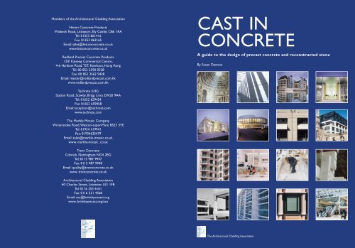
Members of the Architectural Cladding AssociationHiston Concrete ProductsWisbech Road, Littleport, Ely Cambs CB6 1RATel: 01353 861416Fax: 01353 862165Email: sales@histon<strong>concrete</strong>.co.ukwww.histon<strong>concrete</strong>.co.ukRedland Pre<strong>cast</strong> Concrete Products15/F Kaiseng Commercial Centre,4-6 Hankow Road,TST, Kowloon, Hong KongTel: 00 852 2590 0328Fax: 00 852 2562 9428Email: master@redlandpre<strong>cast</strong>.com.hkwww.redlandpre<strong>cast</strong>.com.hkCAST INCONCRETEA guide to the design of pre<strong>cast</strong> <strong>concrete</strong> and reconstructed stoneBy Susan DawsonTechrete (UK)Station Road, Scawby, Brigg, Lincs DN20 9AATel: 01652 659454Fax: 01652 659458Email:reception@techrete.comwww.techrete.comThe Marble Mosaic CompanyWinterstoke Road,Weston-super-Mare BS23 3YETel: 01934 419941Fax: 01934625479Email: sales@marble-mosaic.co.ukwww. marble-mosaic .co.ukTrent ConcreteColwick, Nottingham NG4 2BGTel: 0115 987 9947Fax: 0115 987 9948Email: quality@trent<strong>concrete</strong>.co.ukwww. trent<strong>concrete</strong>.co.ukArchitectural Cladding Association60 Charles Street, Leicester, LE1 1FBTel: 0116 253 6161Fax: 0116 251 4568Email: aca@britishpre<strong>cast</strong>.orgwww. britishpre<strong>cast</strong>.org/acaThe Architectural Cladding Association
CAST INCONCRETEA guide to the design of pre<strong>cast</strong> <strong>concrete</strong> and reconstructed stoneBy Susan DawsonThe Architectural Cladding Association
A short history of pre<strong>cast</strong> materialsForeword
ForewordA short history ofForewordFor me, <strong>concrete</strong> has its own rhetoric. In architectural and structural terms it is unique. It canachieve structural strength with very low porosity and can be moulded to create threedimensionalshapes and finished with textures which range from rugged to highly refined andpolished.The practice has explored the potential of pre<strong>cast</strong> <strong>concrete</strong>; at St. John’s College,Oxford, we created an ‘underworld’ of enclosed spaces, suggesting the idea that they were hewnout of the ground; pre<strong>cast</strong> <strong>concrete</strong> was the material which allowed us to achieve this.Concrete has a complex cultural status. It was a key material in the early days of the ModernMovement; Frank Lloyd Wright used ‘desert <strong>concrete</strong>’ for the base of Taliesin in Arizona.Thesedays Tadao Ando has demonstrated its potential for sculptural form; it is also now associated withthe industrial aesthetic of ‘conspicuous thrift’.Yet it suffered from decades of unpopularity.Why was this? It was associated with cheap, badlydesigned social housing, poorly specified and not designed to cope with problems of water runoff.Thekey to weathering is to use cornices or concealed drainage, as we did in our officebuilding at Crown Place, to throw water back from the façade and to prevent rain falling on ahorizontal surface and draining onto a vertical surface.Pre<strong>cast</strong> <strong>concrete</strong> is not a substitute.The term ‘reconstructed’, although used commonly todescribe a finish with similar characteristics to stone, implies a material pretending to besomething else. Pre<strong>cast</strong> is more than that; it is a refinement of <strong>concrete</strong>, achieving a dimensionalprecision and surface quality by off site manufacture, enabling architects to create components ina way that no other material allows them to do.Architectural solutions arise from the potential of a material: in the case of pre<strong>cast</strong> it is itsthree dimensional adaptability, its strength, and the quality of its surface textures. Understandingthese potentialities is the key to achieving an architectural language of <strong>concrete</strong>.Sir Richard MacCormac3
The Architectural Cladding AssociationThe Architectural Cladding Association (ACA) is a product association within the national body ofthe pre<strong>cast</strong> industry, the <strong>British</strong> Pre<strong>cast</strong> Concrete Federation.The members of the ACA are the major providers of pre<strong>cast</strong> <strong>concrete</strong> cladding and specialarchitectural products for structural applications in the UK, together with one internationalmember who is based in Hong Kong.The members are fully resourced and experienced toprovide a complete service of advice, design development, manufacture and site erection.ACA member companies lead the way in top quality factory engineered <strong>concrete</strong> solutions.Pre<strong>cast</strong> fabrication is safe and sustainable. Both cost and programme are predictable and the useof ‘just in time’ delivery is much faster than traditional construction methods.The overriding objective of ACA members is to provide quality with true value.Members of the Architectural Cladding AssociationHiston Concrete ProductsRedland Pre<strong>cast</strong> Concrete Products, Hong KongTechrete (UK)The Marble Mosaic CompanyTrent ConcretePublished by the Architectural Cladding Association,60 Charles Street, Leicester, LE1 1FBTel: 0116 253 6161ISBN: 0 9536773 3 8© Susan Dawson, 2003All rights, including translation, reserved. Except for fair copying, no part of this publication may bereproduced, stored in a retrieval system or transmitted in any form or by any means, electronic,mechanical, photocopying or otherwise, without the prior written consent of the ACA. Everyeffort has been made to ensure that the statements made and the opinions expressed in thispublication provide a safe and accurate guide; however no liability or responsibility of any kind canbe accepted by the publishers, the authors or the Architectural Cladding Association.Printed and bound in Great Britain by Brown & Son, Hampshire.An imprint of the <strong>British</strong> Pre<strong>cast</strong> Concrete Federation.ACA acknowledges the valued support of the <strong>British</strong> Cement Association in the publication of this book.4
ContentsContents6 IntroductionDesign8 Principles of façade design9 Design and the manufacturing process12 Structural design13 Transport restrictions14 Fixings17 Joints and sealants18 Design development and drawing process19 Pre<strong>cast</strong> <strong>concrete</strong> finishes21 Brick and stone-faced pre<strong>cast</strong> <strong>concrete</strong>Design for construction22 The construction process25 Pre<strong>cast</strong> and sustainability26 Health and safety issuesWeathering27 Causes and types of weathering28 Weathering and designA short history of pre<strong>cast</strong> materials33 The beginnings of <strong>concrete</strong>34 The discovery of Portland cement36 The development of pre<strong>cast</strong> materialsCase studies44 Armagh arts centre, Northern Ireland48 St George Wharf, London52 Merrill Lynch headquarters, London57 Clearwater Court, Reading60 Central Library, Hong Kong62 St Anthony’s primary school, Singapore64 Office campus, Leatherhead, Surrey66 Office buildings, Slough68 St John’s College, Oxford71 The Lawn Building, Paddington Station, London74 Office conversion, London76 Paribas headquarters, London78 Office building, Paternoster Square, London80 Toyota headquarters, Epsom, Surrey82 Housing,Timber Wharf, Manchester84 Sainsbury headquarters, Holborn, London86 North stand, Ipswich Football Club87 Extension, Royal College of Obstetricians &Gynaecologists, London88 Office building, Crown Place, London89 Swimming pool, Oxfordshire93 J C Decaux headquarters and warehouse, London95 Bibliography96 Acknowledgements5
IntroductionA short history ofIntroductionPre<strong>cast</strong> <strong>concrete</strong> is a building material with gravitas. It hassolidity and strength, factors which recall traditionalconcepts of enclosure, yet it has all the advantages of amodern prefabricated product.Pre<strong>cast</strong> is uniquely versatile. Its composition, based onstone aggregate mixes, can be altered to produce a varietyof colours, textures and finishes; in addition, as a <strong>cast</strong>product with high strength, it can be shaped and used ascladding panels to enclose a building, used to createloadbearing structural panels and components, wholestructures or hybrid structures.The most common use of pre<strong>cast</strong> on buildings is ascladding panels and this is reflected in the contents of thisbook.As a structural material, pre<strong>cast</strong> is ideal for this use– it can be shaped to form mullions and spandrels orstorey-height panels. In most cases pre<strong>cast</strong> cladding panelsare <strong>cast</strong> from a mix which will produce the appearanceand texture of natural stone – a specification generallyknown as reconstructed stone. Such mixes make thematerial acceptable in environmentally sensitive areaswhere new projects are required to blend in with existingtraditional stone buildings. Pre<strong>cast</strong> cladding panels can alsobe faced with brick, natural stone and terracotta tiles.6
Pre<strong>cast</strong> cladding panels and components offer many practical advantages compared to other materials:● quality achieved by prefabricated manufacture incontrolled environment, unaffected by weather and labourshortages.This permits rigorous selection and inspectionbefore installation, removing causes of delay on site● prefabrication and phased delivery to site acceleratesthe construction programme and achieves a weathertightbuilding enclosure at the earliest opportunity● on-site ‘wet trades’ are minimised; if internal pre<strong>cast</strong>elements are prefinished, wet trades can virtually beeliminated● site installation by skilled teams, usually without scaffold.● dense pre<strong>cast</strong> <strong>concrete</strong> gives excellent soundattenuation and inherent fire resistance● glazing, fixings, thermal insulation and vapour controllayer can be incorporated in the factory before delivery tosite● fabric energy storage potential of pre<strong>cast</strong>; thermal mass,especially when used as exposed pre<strong>cast</strong> floor slab, helpsto control building temperatures● pre<strong>cast</strong> cladding panels produce a thinner external wallthan conventional double-skin walls, increasing the lettablefloor area.● long-term durability - <strong>concrete</strong> has a design life of wellover 60 years● security7
DesignDesignPrinciples of façade designEven at the basic design stage,of a façade,the decision to usepre<strong>cast</strong> panels has important implications. To realise thefaçade design in a creative way the architect should be awareof potential pitfalls. For example, the design decision to placea panel joint in a certain position sets up a chain ofimplications - how the panel is made, how it is fixed on siteand how the contract is managed; these in turn will haveimportant results on cost and speed of construction.Key stages in the design of a pre<strong>cast</strong> <strong>concrete</strong> façade aredetermining where joints between panels will be positioned,and whether windows will be set within the panel or framedby spandrels and mullions. As the panels have to besupported and restrained by the structure, floor levels andcolumn grids will determine to a large extent where jointswill fall. The most economic design results come from theuse of panels as large as practically possible – the lowestnumber of panels, joints and fixing hardware giving thefastest construction programme. But this must be balancedHolistic approach to design & procurement methodsToo often in the past, with traditional procurementmethods leading to sequential appointment of tradecontractors, it was impossible to arrange for designissues to be addressed in a holistic manner.The resultwas technical problems with compromised details,wasted time and money. In the end it was the clientwho paid. Sir Michael Latham’s 1994 reportConstructing the Team addressed this inefficiency andcalled for a radical change in attitudes and culture.Theindustry must change from confrontation to cooperation.By driving out inefficiency and waste, Lathamreported, construction costs could be cut by 30%.Partnering was a key recommendation in the report; itwas a way to manage the design process moreeffectively, with all the key players being appointed earlyenough to exchange information and ideas.Theseproposals were further emphasised in Sir John Egan’s1998 report, Rethinking Construction. The targets set byEgan are well known and include a demand for moreeffective procurement using strategic alliances. Bothby the limitations of site cranage capacity, transport and, inexceptional circumstances, factory resources.Pre<strong>cast</strong> offers the opportunity to prefabricate theexternal façade in the factory rather than on the site, withall the advantages of economy and speed of constructionwhich that entails.Design decisions on window positions willaffect this. A panel with inset ‘punched’ windows gives theopportunity for factory-installed window frames and glazing,whereas windows set between spandrels and mullions needwindow openings which have to be formed by at least 2 andoften 4 panels; frames and glazing would have to be installedon site.Insulation, when detailed to be applied to the inside faceof the cladding, is also best fixed at the factory.This avoidssite work and the difficulties of fixing insulation around edgebeams and columns.Design and the manufacturing processIt makes sense for an architect involved in the design ofLatham and Egan demand higher quality and greatercertainty of cost and time.Two principles emerge, whichare relevant to all specialist contractors, not only to thepre<strong>cast</strong> cladding industry.1 Abandon lowest capital cost as the value comparator2 Involve specialist contractors and suppliers in designfrom the outset.For pre<strong>cast</strong> cladding the key interfaces are with● structure● windows/curtain wall● M & E services● material suppliers eg brick, stone etcNo matter what procurement route is followed, it isvital to have the interface specialist appointed earlyenough to enable detailed design meetings at whichmaterials, specifications and design decisions can betaken against a background of expert knowledge. In thisway the architect, engineer, pre<strong>cast</strong>er, glazing contractorand services engineer can contribute to achieving amore effective result for themselves individually andultimately for the client.8
Designpre<strong>cast</strong> components to understand how they aremanufactured. Understanding leads to an efficient andbuildable design; it may also inspire a creative approach.The economies of mould usePre<strong>cast</strong> units are <strong>cast</strong> in purpose - built moulds which maybe constructed of steel, GRP, timber and even <strong>concrete</strong>.Some manufacturers use tilting steel vibrating tables aspart of their mould strategy. These are very suitable for<strong>cast</strong>ing flat panels and the mould can be tilted to a verticalposition to act as a strong back for handling, reducingstress and allowing panels to be thinner.Timber is the material most frequently used. A singletimber mould can be used to <strong>cast</strong> about 30 identical units(tolerances are difficult to maintain after 30 <strong>cast</strong>ings).As atypical mould for a complex cladding unit costs severalthousand pounds, efficient mould use is important.A steel mould is capable of <strong>cast</strong>ing several hundredunits but costs about three times dearer than that of atimber mould. Therefore to achieve a similar costamortisation, the steel mould would need to <strong>cast</strong> at least90 units. Manufacturers seldom come across projects with90 or more units sufficiently alike to justify a steel mould,nor do they see lead time programmes which would allow90 <strong>cast</strong>ing days - assuming a daily <strong>cast</strong>ing cycle.In any manufacturing operation, repetition is the keyto economy. 30 identical <strong>cast</strong>s from a timber mould wouldgive an optimum unit cost, but in practice pre<strong>cast</strong>ers workwith much lower repetition and frequently have only ahandful of identical panels.Design of pre<strong>cast</strong> cladding elements should aim for anaverage repetition of more than 10.Although any complexproject will have elements with few or no repeats, theobjective is to raise the average. Similar factors apply toThe graph illustrates the effect of repetition of <strong>cast</strong>ing on cost. For atypical unit <strong>cast</strong> in a timber mould, the cost of 30 identical units istaken as unity. As repetition reduces to 10 <strong>cast</strong>ings the cost risesgently; below 10 <strong>cast</strong>ings it rises rapidly.pre<strong>cast</strong> units clad with granite or other stone slabs; theslabs must be easy to handle and of simple design. Toreduce the effects of low repetition, pre<strong>cast</strong> elements canbe designed to form groups of relatively similar units, ableto be <strong>cast</strong> by making small alterations to the mould. Atypical example of how a basic mould can be adapted isshown (above top). A more complex example, the steelmould for floor units of Michael Hopkins & Partners’Inland Revenue building in Nottingham, is shown in (abovelower).The mould was made so that a series of differenttimber ends could be inserted where required. Pre<strong>cast</strong>ersprefer to <strong>cast</strong> in a sequence of largest to smallest: this mayhave cost and lead-time implications.Finishing processes affect panel costs and wherepossible alternative acceptable finishes should becompared (see section on pre<strong>cast</strong> finishes).9
DesignThe manufacturing processIn general pre<strong>cast</strong> mixes will contain aggregates of lessthan 20mm diameter and a higher than average finescontent to allow a relatively smooth surface finish.Commonly used aggregates, selected from sources in theUK and abroad, include granite, limestone and basalt. Allpre<strong>cast</strong> works have a large aggregate store withcomputer-controlled batching plants to give precisecontrol of the mix.The pre<strong>cast</strong> production process starts in the CADdrawing office where every unit is drawn and thereinforcement is designed. The drawings then go to themould shop, a key stage in the process which requires ahigh degree of skill, as the mould must be strong enoughto resist deflection under the strain of the <strong>cast</strong>ing process.Some manufacturers also use vibrating tables as thebasis of the mould unit. These are smooth-polished steel‘tables’ which act as the base of the mould; the sides arePre<strong>cast</strong> units are detailed in the drawing officeStone facings are positioned face-down in the base of the mouldA timber mould under constructionThe bending of steel reinforcement has been automatedThe reinforcement is laid in the mouldStainless steel fixings are fabricated for cladding components10
Designformed by timber moulds clamped with jacks.The amountof carpentry work is reduced, and units with commonfeatures can be produced by altering the positions of thetimber sides.The completed mould is then fitted with itsreinforcement cage, which is usually in the form ofdeformed high-tensile steel bars.Cast-in threaded lifting and fixing sockets are alsopositioned at this stage.The mix is poured in and vibratedto fully compact the <strong>concrete</strong>.The units must then be left in the mould for at least16 hours or until they have developed sufficient strengthfor handling.Their final strength will range from 40 to 70N/mm 2 .Most pre<strong>cast</strong> units are finished to remove surfacelaitance and to expose slightly the underlyingaggregate/cement matrix. This is done by acid etching,rubbing or by grit blasting – (see pre<strong>cast</strong> finishes).The mix is poured into the mould...After <strong>cast</strong>ing, pre<strong>cast</strong> units are craned into the yardA mock- up unit ispropped in the yardand vibrated to fully compact the <strong>concrete</strong>Definitions: What is pre<strong>cast</strong>, reconstructed and <strong>cast</strong> stone?Pre<strong>cast</strong> is also described as reconstructed stone or reconstituted stone. It should not be confused with what is generallyknown as <strong>cast</strong> stone.Pre<strong>cast</strong> is produced by the wet-<strong>cast</strong> method, as described above, and is an extremely strong structural material with alow absorption rate and a variety of finishes and textures.Cast stone is generally produced by the semi-dry method, also known as the 'moist earth' mix method. As the nameimplies, the material has a low water content and has the same texture as moist earth when freshly mixed. It isconsolidated in the mould by ramming or tamping. Semi-dry <strong>cast</strong> stone has a surface texture and colour closelyresembling those of some natural stones. It tends to have relatively lower strength and higher porosity, and can only bemanufactured in fairly small unit sizes.11
Design4metre high and 3metre-wide storey-height panel wouldusually be 150-180mm thick; a spandrel 4 - 6metres longwould be 140-160mm thick. Panels with applied finishessuch as brick or stone will be correspondingly thicker.Top: structural panelswith integrated insulationat J.C. Decaux Right: astructural componentwith a high quality finish.Below: hybridconstruction at Toyotaheadquarters buildingLoadbearing panelsPre<strong>cast</strong> <strong>concrete</strong> is of a very high specification and itsstructural properties can be used to advantage either as loadbearing wall units or as part of a complete structure. Loadbearing units are designed in accordance with BS8110:1997The structural use of <strong>concrete</strong>.Pre<strong>cast</strong> structural wall panels can provide an efficientstructure solution and increase lettable floor area in officebuildings. Pre<strong>cast</strong> crosswalls were used at Timber Wharf,Manchester (see case study), to form party walls betweenapartments. The walls were <strong>cast</strong> with integrated serviceducts and a smooth surface finish so that they did not needto be concealed behind a secondary lining but could be leftexposed.Pre<strong>cast</strong> panels can also be used to provide bracing inframed structures. (See J. C. Decaux case study where thepanels are also <strong>cast</strong> with integral insulation in a sandwichconstruction).Structural designThe most common use of pre<strong>cast</strong> on a building is as nonstructuralcladding panels, but it can also be used asloadbearing structural panels and components and as wholehybrid structures.Cladding panelsThe panel must be strong enough to resist site-appliedloads (in most cases from wind) and handling stresses(which are usually the greater force).The panel connections, joint widths and sealants mustaccommodate both movements in the structure andthermal movements of the panel.Design responsibility rests with the pre<strong>cast</strong> specialistwho will design in accordance with BS 8297:2000 Designand installation of pre<strong>cast</strong> <strong>concrete</strong> cladding.Panel thickness is determined by structural design, bythe need to provide adequate cover to the reinforcement,and by the need for sufficient thickness to contain andretain fixings and lifting devices. As a general guide, aPre<strong>cast</strong> structuresPre<strong>cast</strong> combines the potential to be used as a structuralcomponents with the ability to achieve a high quality finishwhich needs no additional treatment or fire-proofing. (seepre<strong>cast</strong> structure case studies)Hybrid structuresHybrid structures are those in which structural pre<strong>cast</strong>component are combined with structural steel or with insitu<strong>concrete</strong>.In the case of steel hybrid structures, steel stanchionsand beams are pre-encased, in most cases with areconstructed stone mix, and used in combination withpre<strong>cast</strong> components with the same mix.Concrete hybrids are those in which pre<strong>cast</strong>components are combined with <strong>cast</strong> in-situ <strong>concrete</strong>.Thepre<strong>cast</strong>, with its high quality finish, is exposed.The <strong>cast</strong> insitu<strong>concrete</strong>, which is generally in the form of beam stripsto give structural continuity, is hidden.Both forms of hybrid structures are accurate and fastto build. Hybrid structures allow fabric energy storageprinciples to be used, contributing to the energymanagement of the building.12
DesignTransport restrictionsThe method by which panels and components aretransported to site will limit their size.The maximum heightthat can be transported on principal roads within the UK is4.9metres overall. This leaves approximately 4 metresavailable for the panel.As panels invariably travel in a slightlyless than vertical position, the height saved usuallycompensates for seating bearers etc,giving a maximum panelheight of 4metres, although length, weight and stability willalso affect this height.There are no restrictions on loads up to 2.89metreswide. For 2.89 to 4.1metres wide loads, the police force ofeach county through which the load passes must be notified(usually by fax) not less than two days beforehand.For 4.1 to 5 metres wide loads, the police force of eachcounty must be notified at least seven days beforehand.Police permission is required before the load is moved, andthe load requires a police escort.An extendable trailer canaccommodate lengths of up to 18metres, usually withoutpolice permission.Thermal and acoustic insulationReconstructed stone, being dense <strong>concrete</strong>, is a relativelypoor thermal insulator and external walls will require someother form of thermal insulation to meet Building Regulationrequirements.Thermal insulation can be fixed directly to the structureor factory-applied to the back of a pre<strong>cast</strong> panel.The lattermethod is particularly useful for parts of the structure, forinstance column casings, where it is difficult to fix insulationon site.Composite pre<strong>cast</strong> panels with a thermal insulationcore have rarely been specified in the UK due to problemswith cold bridges. This has now changed with theintroduction of new proprietary systems such as Hardwall,which allow the energy storage capacity of the inner skin tobe exploited.As reconstructed stone panels are dense and heavy,theyoffer very good sound reduction properties. Windowswithin the panel will reduce their effectiveness. Loss throughjoints is small.Most panels are carried on A-framesMethod of transporting a single large unit13
DesignIsometric view showing positions of loadbearing and restraint fixingson one side of a pre<strong>cast</strong> cladding panelFixingsThe primary purpose of fixings is to support the dead loadof a pre<strong>cast</strong> cladding panel and to restrain it from thedirectional movement caused by applied loads.Although the design of fixings varies widely dependingon the type of cladding, the size of the panel and thestructure of the building, it follows a number of generalprinciples. In order to achieve a safe, efficient and costeffectivefixing scheme, a number of basic factors shouldbe addressed at an early stage.The support of a panel is provided by loadbearingfixings which transfer its weight on to the structuralframe. Loadbearing fixings can take the form of <strong>concrete</strong>nibs <strong>cast</strong> integrally with the panel. If the raised access floorzone has insufficient depth to accommodate nibs, thepanel can be supported on a pair of stainless steel angles,each set on shim packs to allow for any adjustment oflevel. To reduce the tendency for the panel to falloutwards, it should be supported in line with its centre ofgravity. It is also better to support panels at their basesrather than to top-hang them, as <strong>concrete</strong> whensupported remains in compression.Restraint fixings are intended primarily to resist windloads and allow adjustment for both line and plumb. Fourrestraint fixings per panel are usually used, set as close tothe corner as is practical. Restraint fixings can take theform of a grouted dowel, but are more often designedwith an angle, or plate, which allows the panel to beattached positively to the structural frame as soon aspossible after installation.A pre<strong>cast</strong> balcony unit with projecting bars for stitching into thereinforcement of the main structural slabThe design of restraint fixings must also allow forpermissible deviations in the manufacture and erectionof the panels and the construction of the structuralframe. Each restraint fixing must allow for adjustmentsof typically + or - 25mm in all three dimensional planes.The adjustment may be achieved by the use of shimpacks, <strong>cast</strong>-in channels and/or slotted holes in the steelfixing angles or plates.A structural frame of <strong>concrete</strong> or<strong>concrete</strong>-encased steelwork may also incorporate <strong>cast</strong>inchannels. The pair of restraint fixings furthest fromthe panel’s support fixings should allow for movementcaused by thermal effects and deflection, by using PTFEwashers. Angles, plates and washers with inter-lockingserrated faces will be required in situations where anyload acts in line with a slotted hole.The support and restraint functions of a fixing canbe combined. A <strong>concrete</strong> nib may include a hole for adoweled connection, and a support angle may be boltedto a <strong>cast</strong>-in channel, socket or drilled hole in thestructural frame.Grade 1.4301 (previously Grade 304) austeniticstainless steel is generally used for both support andrestraint fixings. Grade 1.4401 (previously Grade 316)stainless steel is more suited for use in industrial, highlycorrosive or marine environments. Mild steel fixings mayonly be considered where conditions are permanentlydry, such as on the warm side of a vapour barrier. Insuch circumstances steel angles should be galvanisedand nuts and bolts sherardised for extra protection.14
DesignRestraint fixingsRestraint fixing to a <strong>concrete</strong> structure. A simple <strong>concrete</strong> bearingcorbel with dowel restraint is the most economical detail but theheight of the corbel may interfere with the raised access floor detailAngle restraint fixing to a <strong>concrete</strong> structure. Slotted holes in theangles give tolerance. The stainless steel studs screwed into the socketin the panel have washers and nuts on both sides of the angle. Theseare used as a push-pull device to position the panel accurately.Angle restraint fixing to a steel structure. Seenotes to angle restraint fixing above right.Angle restraint fixing to a steel structure,with restraint socket <strong>cast</strong> into floor deck.Detail (as shown above right) of threadedand drop dowel restraint fixingRestraint fixing to a steel structure. The steel plate is welded tothe column at the fabricator’s works, and the detail requiresaccurate positioning of panels and structure.16Restraint fixing usingstainless steel threadeddowel pins between panels.Restraint fixing usingstainless steel drop dowelpins between panels. Thepins are held inside stainlesssteel tubes until required.
Joints and sealantsA pre<strong>cast</strong> <strong>concrete</strong> cladding panel can be considered asbeing practically impervious. But this serves littlepurpose if the weather can penetrate at the jointsbetween the units. It is essential to pay the closestattention to the specifying and treatment of joints, frominitial design to installation and maintenance of sealants.As the maximum overall height that can betransported by road is about 4.9 metres, one dimensionof a panel should not exceed about 4 metres. However,since this is greater than the typical storey height ofabout 3.9metres, panels will usually be wide enough inthe other direction to match the column grid.Width of jointsIn order to remain attached to the two faces of a joint,the sealant has to be able to accommodate movementdue to thermal or other factors. This capacity iscommonly termed the ‘movement accommodationfactor’ (MAF) and varies between different sealantmaterials. A typical sealant might be able to ‘stretch’about 25% of its nominal width.Thus for an anticipatedmovement of say 4mm, a nominal joint width of 16mmis suggested.The minimum joint width is generally 10mmplus appropriate allowances for thermal and differentialmovement.If units are ‘stacked’, all thermal movement has to beaccommodated at the top of the stack, and this couldmean a much wider joint than normal.Even if panels and hence movements, are small, it isnot good practice for primary joints to be less than12mm wide - narrow joints make small dimensionalvariations apparent.is ‘interrupted’ by lifting devices; it could collectmoisture and cause problems with freezing.If moisture does get through the outer seal, it willeventually reach a vertical joint and descend. It is goodpractice to allow for drainage at the bottom of verticaljoints. This would also cater for any condensationforming on the inner face of cladding. A properlydesigned façade and insulation should deal withcondensation risks so that no moisture forms in the firstplace.Shadow gaps and recessesRecessing joints into the surface of the panel canenhance the simple profile advocated above. This willdisguise the actual line of the joint by making it adeliberate feature of the façade. It also provides anatural route for rainwater to flow down, enabling dirtto be concentrated in predefined areas.Even within a shadow gap, the sealant should berecessed a further 3mm or so back from the front faceof the <strong>concrete</strong>. This minimises the risk of primergetting on to the front face and also helps ensure thatthe <strong>concrete</strong> against which the seal is acting is sound,especially if the surface has been textured.When sealingpanels with a front facing of stone or brick, the secondseal should be against the backing <strong>concrete</strong> and not thefacing material.PrimingConcrete and stone should normally be primed beforeapplying the sealant to improve adhesion. Success islargely dependent on thorough preparation and carefulpriming.Joint profileThe simplest profile is a straight square joint. This hasseveral advantages: the panel is easier to <strong>cast</strong>; it allowsfull horizontal adjustment during erection; it gives fullspace for the sealant; it allows inspection of the innerseal; it does not interfere with other aspects.A double seal is usually specified at the frontsurface. Occasionally a third inner seal of impregnatedfoam material is also used on the inner face.Sometimes a ‘joggle’ joint is specified. While thislooks a good solution in theory, in practice it should beavoided as it presents many problems. It is more difficultto <strong>cast</strong>; it restricts adjustment; it does not provideenough space for a double seal; it prohibits inspection; itSealant materialsThere are several types of sealant available on the market.Of these the most commonly used is the one-part, lowmodulus, silicone or ciloxane rubber sealant. These aregun-applied against a backing strip of foam polyethylene tofill the gap.The outer surface cures on exposure to air togive a smooth finish.When seals are applied to a stone-faced panel, thereis an increased risk of staining of the stone by thesealant. Recently a range of more advanced hybridsealants has become available. All these materials comein a range of colours allowing a near match to many<strong>concrete</strong> and stone finishes. When properly installed byskilled operators, sealants should give a life in excess of17
Design25 years. If the seal is damaged, the simplest repairmethod is removal and replacement of the strip affected.Mix and specificationThe mix for a pre<strong>cast</strong> element with a reconstructed stonefinish is complex. Compared to the mixes used forstandard in-situ <strong>concrete</strong>, it has a higher cement contentand low water/cement ratio, with minimal slump and theproportion and size of the aggregates are closely related tofinish and texture. ACA members have extensive samplelibraries, and will make samples to order before tendering.Reconstructed stone mixes should be specified against asample approved at pre-tender stage, so that a truecomparison of colour and texture can be obtained frommanufacturers. Members of the ACA are prepared to agreea quality of specification with the client on every contract.Architects should be aware that not all manufacturers willbe capable of comparable quality management.The design development and drawing processTo develop the design of a pre<strong>cast</strong> <strong>concrete</strong> façadeproject, co-operation is needed from all concerned inproviding information, in making decisions and inproviding approvals at the right time.Initially the pre<strong>cast</strong>er needs basic dimensioneddrawings from the architect and engineer of elevations,plans and sections, together with access to the keyinterfacing specialist contractors.The pre<strong>cast</strong>er’s drawing office will prepare initialgeneral arrangement drawings (GAs). These are issuedto the architect and engineer in the first instance andmeetings are held to discuss the development of designprinciples and particular details.A common system for indicating approval status is: -Status C Architect’s and engineer’s comments must beimplemented and the drawings re-issued.Status B The work can proceed taking account of allcomments.Status A Fully approved with no comments. This is aconstruction status drawing.As this process proceeds every aspect of the façade isdefined and detailed in co-ordination with otherspecialists who may give and receive ideas and makedetailed improvements. A vital element of the pre<strong>cast</strong>er’sdesign development is the preparation of what is knownas ‘builders work’.This covers interface details with otherkey specialist contractors. On cladding contracts, a keyinterface is with the structural frame contractor and theopportunity to have support brackets, restraint fixingplates and holes formed during fabrication saves time andcost during site erection. Equally valuable interfacingshould take place with the window/curtain wallcontractor and the M & E specialist.A series of detailed drawings is then prepared by thepre<strong>cast</strong>er to communicate and agree the details.Obviously this process can only take place if theinterfacing specialist contractors have been appointed.Sequential procurement largely destroys the opportunityfor such valuable interfacing.Ultimately the pre<strong>cast</strong> drawings become a definitivesource of information enabling the architect and, to a lesserextent, the engineer to review the full detail of the scheme.Shop drawingsPart way through the GA approval process, i.e. whensufficient drawings are at B and A status, the pre<strong>cast</strong>er’sdrawing office begins to prepare shop drawings. Shopdrawings are only usually circulated within the pre<strong>cast</strong>factory. These are created by extracting each façadepanel from the GAs and producing manufacturing detailsfrom which the mould is fabricated, the reinforcementcut, bent and assembled and the <strong>cast</strong>-in hardware e.g.lifting and fixing sockets, is positioned. Finishes and<strong>concrete</strong> mix specification are defined.GA preparation may involve many design meetings;provision of information and speedy decisions andapprovals are vital to the efficient progress ofmanufacturing to enable the factory to manufacture inthe necessary sequence and volume to satisfy the siteconstruction programme. If the GAs become morecomplicated, the unit types are certain to increasewhich, in turn, generates more shop drawings. Thisresults in more moulds and more mould alterations.The GAs are key drawings used by planners forproduction and construction programming and later bythe erection team to assemble the cladding panelscorrectly and accurately on the structure.For the ACA member, every project is unique andprogramme times are planned carefully to suit a particularproject. However to give guidance on a typical £1 to £1.5million project the following periods are reasonable, as18
TYPICAL PROGRAMMEWeeksOperation 0 1 2 3 4 5 6 7 8 9 10111213141516171819202122232425262728293031323334353637383940Pre<strong>cast</strong>er receives instruction to proceedDesign development inclusive of G.A. plansIssue of builders work informationShop drawingsInitial mouldsManufactureSite startshown in the typical programme opposite. Clearly thepre<strong>cast</strong>er must have good, basic, thoroughly dimensioneddesign drawings from the architect and the engineer with theinstruction to proceed. A reasonable turnaround ofcomments on GAs and approvals is essential to start theshop drawing preparation; two weeks is the industrystandard. Changes of mind or last minute decision-makingcan result in lengthy delays and rapidly escalating costs.Pre<strong>cast</strong> <strong>concrete</strong> finishesThe way in which a pre<strong>cast</strong> surface is finished will have adistinct effect on its appearance. Some techniques exposethe aggregate in its natural state; others physically changethe appearance by abrading or fracturing the surface.Within each technique the degree of exposure can bevaried, with the result that a considerable variety of effectscan be achieved.Finishing processes can be divided into two basiccategories: wet and dry. Common techniques used tofinish pre<strong>cast</strong> <strong>concrete</strong> components are described below.Wet techniquesAcid etchingAcid etching is a method of removing the very thin layerof laitance, formed by fine aggregate and cementparticles from the <strong>concrete</strong> surface, exposing thetexture and colour of the matrix beneath. Hydrochloricacid in either diluted or gel form is used to etch thesurface.The depth of exposure is controlled by the levelof dilution and/or the length of time the acid remains incontact with the <strong>concrete</strong> before it is washed off withwater. Surfaces may also be etched more than once if agreater degree of exposure is required.Care should be taken when acid etching verticalsurfaces to avoid streaking. Very light degrees ofexposure should be avoided as this often fails to removeTop: polished columns on a grit blasted plinth. The corner panelsbehind were tooled to give horizontal rusticated bands.Below: an acid-etched surface is washed down with water19
DesignA selection of grit blasted pre<strong>cast</strong> unitsall the laitence; the residue may tend to craze in time asit is exposed to the weather.Ideally etching should be undertaken three to fourdays after <strong>cast</strong>ing, when the <strong>concrete</strong> has attainedsufficient surface hardness but not to the extent that itis difficult for the acid to penetrate.After etching, minorblowholes exposed by the removal of the laitance mayhave to be rubbed in.RetardingThere are three main methods of retarding: a retardingagent is painted on to the formwork surfaces; retarderpaper is laid in the formwork; surface retarders areapplied after <strong>cast</strong>ing. In each case the retarder preventsthe surface of the <strong>concrete</strong> from hardening and allows itto be removed by either high pressure washing with wateror by brushing. The depth of retardation is controlled byusing different strengths of proprietary products.Dry techniquesGrit blastingGrit blasting can produce a finish similar to acid etching orit can be used as a more aggressive means of exposing thecoarse aggregates. Different grades of grit - from fine tocoarse – will determine the depth of exposure revealed.In its most aggressive form grit blasting will physicallyabrade and fracture aggregate particles.The equipment isdriven by compressed air and the force at which the gritparticles hit the <strong>concrete</strong> surface is controlled byadjustment of the air pressure.ToolingTooling is undertaken with a variety of pneumatic orelectric hand-held equipment, ranging from needle guns tobush hammers and chisel point tools.The points within aneedle gun may be varied in length depending upon thedepth of exposure required.This will also be influenced bythe pressure used and the duration of the treatment.The20
same applies to the use of other tools.Tooled finishes givea more rustic appearance due to the aggressive nature ofthe finishing techniques.PolishingPre<strong>cast</strong> panels can be polished to varying degrees ofsmoothness; from a ‘honed’ matt finish to a high glosspolish which can resemble that of granite. Polishing ofsmall components, or those with rebated surfaces, is bestcarried out by hand; large, flat pre<strong>cast</strong> units can bepolished mechanically.A typical polishing machine will move over the pre<strong>cast</strong>unit with a preset polishing and pressure programme.Using a diamond-tipped plate, it will grind about 3mm offthe face of the panel; this may reveal a coloured aggregate.A series of abrasives is then applied to the surface. Thefinal finish depends on the fineness of the polishing headsand the number of times they are passed over the panelsurface.all the bricks for that panel being available.Panel size and thicknessPanels should ideally be sized in normal brick modulesas with any wall.There is no practical limit to the size ofpanel other than that of transport. When designing thepanel to take loads, including self-weight, the thicknessof the bricks is not taken into account.Brick layoutAny normal brick bond can be provided, althoughexcessive use of headers should be avoided. Edges ofpanels, particularly at returns and reveals, should beBrick and stone-faced pre<strong>cast</strong> <strong>concrete</strong> panelsBrick-faced pre<strong>cast</strong> panelsTraditional brickwork is a popular and successful facingmaterial, combining a traditional appearance with thequality, strength, speed and durability of pre<strong>cast</strong> <strong>concrete</strong>.Brick: properties and selectionA brick with good uniformity of colour will minimise therisk of colour changes on different panels. The ideal typeis a brick perforated with three holes; a clean cut throughthe holes will provide a secure anchorage for fixing intothe panel. Solid bricks can be cut to give a dovetail anchor.The tolerances set out in BS3921 are not really tightenough. A measured length of 24 bricks will vary from5235mm to 5085mm, or ±3mm per brick. Most supplierswill improve on these figures by arrangement. Ideallybricks should be made with a tolerance of +1to –2mm.Ideally a maximum water absorption figure of 12%should be specified.A brick manufacturer should be chosen who is able tosupply all the bricks including any specials and who is ableto cut ‘standard’ bricks.Delivery periodBricks with an extended delivery period for specialsshould be avoided; the production of a panel depends onTop: a polishing machine in action Below: two examples of polishedfinishes21
DesignTop, left and right: brick and Portland stone-faced pre<strong>cast</strong> panels Below, left to right: knapped flint-faced pre<strong>cast</strong> panels, brick-faced pre<strong>cast</strong>panels and terracotta-faced pre<strong>cast</strong> panelsexamined to ensure that no unfinished faces are visible.Patterns can be formed on panels without difficulty.JointsThe joint between bricks is usually detailed as a nominal10mm.These can be pointed at the pre<strong>cast</strong> factory, usingstandard cementitious materials, with the finish to thejoint being the same as for any hand finished pointing.Alternatively they can be left recessed to allow handpointing on site after erection. But the joints betweenbricks will not look the same as the joints between thepre<strong>cast</strong> cladding panels. The latter must accommodatetolerances in manufacture and erection as well as thermalmovements.These will normally be finished with a gunnedinsealant to provide a fully weathertight envelope. andcannot normally be as narrow as 10mm.The high standard of workmanship used in producinga brick faced panel reflects factory conditions. Althoughthere is a degree of latitude, the joints will all be true andhorizontal, and the perpends will all line up. This isachieved by placing each brick in a pre-set grid in themould.Any in-situ brickwork that adjoins this will need tobe of a similarly high standard.The treatment works as well on columns andspandrels as on flat panels. Brick-faced structural columnscan be erected on site as a single element ready to acceptloading. At the Inland Revenue Centre in Nottingham,over a thousand storey-height piers support the pre<strong>cast</strong>floor plates. Spandrels can also be structural, spanningbetween supports and even carrying central mullions.Theability to span removes the need for falsework,particularly with overhangs and arches, which can bedelivered and erected as a complete unit. Brick facedpre<strong>cast</strong> can be erected with speed without the need forscaffolding. Since it is fabricated off-site there is a hugesaving in site programme time, unaffected by weather orlabour.22
Stone-faced pre<strong>cast</strong> <strong>concrete</strong> panelsThe methods of attaching natural stone or granite to apre<strong>cast</strong> <strong>concrete</strong> cladding panel were developed in theearly 1970s, in particular for the façade of the EMIcentre in Tottenham Court Road, London. It was abuoyant building period for the commercial sectorwhich highlighted the many advantages of off-siteprefabrication, such as the achievement of a speedyscaffold-free enclosure, using large components with anengineering quality of accuracy. Since then nearly allnatural stones have been used with pre<strong>cast</strong> systems,including limestone (both hard and soft), sandstone,granite, slate and marble. The major challenge faced bythe pre<strong>cast</strong> <strong>concrete</strong> cladding industry and natural stonesuppliers was that the natural facings are fairly thincompared to the <strong>concrete</strong> panel and have different ratesof thermal movement. A method of attachment wasrequired which would not only support theconsiderable weight of the facing but also allowsufficient independent movement to eliminate thermalcracks or even worse, damage to the mechanical fixingsystem.The following method of attachment has proved tobe so efficient and durable that, on more that oneoccasion after a terrorist bomb attack, the stone facingshave remained in position on the pre<strong>cast</strong> <strong>concrete</strong>panels even when the latter have been totally dislodged.Preparation of stone facingsThe stone supplier prepares the stone facings inaccordance with the <strong>concrete</strong> panel drawings or cuttingschedules. Tolerances are tight and it is common tospecify plus or minus 2mm in every direction. Codes ofPractice state the minimum thickness for each type ofstone; the supplier will slice the stone two millimetresthicker than the minimum requirement.The stone supplier drills holes in the back face ofthe stone; these are to accommodate 6mm diameterstainless steel pins inclined at an angle of between 45 to60 degrees at a rate of approximately 11 to the squaremetre or whatever is demanded by other influences.Thepin will project approximately 60mm into the <strong>concrete</strong>panel and will be glued into the stone to a depth of atleast two thirds of its thickness. Neoprene grommetsapproximately 15mm long are added to the pins to takeup differential movement between the two materials.Laying the facings in the mouldThe stone facing panels are positioned face-down in themould; this is normally a conventional timber mouldthough, in some cases, the stone facings may span an opengrid of support timbers as the seal is at the back face ofthe stone.JointsThe joints between the stone facings are usually 6 to10mm wide to facilitate the application of either hard ormastic pointing after <strong>cast</strong>ing. The joints are then sealedwith a waterproof tape to eliminate ingress from thebacking <strong>concrete</strong>. Sometimes a polyethylene rod isplaced between the modules as an added precaution, forinstance when the rear face of the stone is uneven.MovementTo allow for differential thermal movement, it isnecessary to provide a bond breaker between the stoneand the <strong>concrete</strong>, the most common form being asimple polythene sheet; liquid applied silicone or a PVAsolution has also been used to good effect.CastingThe backing <strong>concrete</strong> (usually approximately 150mmthick) and reinforcement cage is put in place and themould is vibrated in the usual manner.Apart from pointingbetween the stone facings, very little attention is requiredto the unit, except for a clean down.This is the only method of support for natural stoneand its success is endorsed by its inclusion in BS 8298.The same process is adopted for attaching naturalstone to complex features such as arches; an example isshown in the case study of the new Merrill Lynchheadquarters in London. In most respects the designand manufacturing requirements of stone-faced<strong>concrete</strong> panels are identical to any other category ofpre<strong>cast</strong> <strong>concrete</strong> cladding. When produced in a‘punched’ panel arrangement, windows can be fixed atthe pre<strong>cast</strong>er’s factory and insulation can be provided asan integral part of the system.23
Design for constructionDesign for constructionThe construction processPre<strong>cast</strong> <strong>concrete</strong> panels are ordered before constructionstarts on site. Early agreement on panel design enables thepre<strong>cast</strong>er to undertake manufacture, while on siteactivities begin in earnest; the two activities then continuein parallel. Pre<strong>cast</strong> manufacture allows a phased delivery,so units can be delivered to site to an achievable andagreeable programme that is pre-arranged with the maincontractor or construction manager.Panels are delivered in a near vertical position(depending on height) supported by ‘A’ frames fixed to atrailer or, in the case of very large panels or small units,delivered flat on a trailer bed.Once on site, panels are fixed by the manufacturer’sown team or a specialist pre<strong>cast</strong> erector. They are fittedwith <strong>cast</strong>-in lifting devices so that the panel can be lifted ina single crane movement from the delivery vehicle andplaced directly on to the building – a form of ‘just in time’construction. This makes for faster construction, avoidsdouble handling (taking up hook time on the site crane)and eliminates the need for storage on site. Erection takesplace immediately after the structural frame has beencompleted to give (together with the roof) aweatherproof envelope for following trades. Scaffolding isnot usually required other than when fixing panels on tothe face of plain walls, for example shear walls, where therear of the panel is inaccessible.Pre-levelled shims support the panels in a levelposition and restraint fixings secure them. When thepanels are safely in place, the crane hook is released asquickly as is safe to do so.After a group of panels has beenfixed, they are plumbed and lined in together. About 30panels can be fixed in a typical working week, whichincludes preparation (e.g. bolting on brackets) and finishingtasks such as applying fire-stopping. Very little exteriorfinishing work is required, apart from sealing jointsbetween panels (frequently done from mobile cradles).The external skin is completed with thermal insulationand dry lining.Co-ordination with other tradesGreat saving in costs can be made by co-ordinating designand detailing of the cladding with ‘interface’ contractors –structure, glazing and M&E.Co-ordination of panels and glazingAlthough windows may be fitted on site, it is also possiblefor entire glazing units to be fitted at the pre<strong>cast</strong> factory.Factory-fixed window frames and glazing require thewindow contractor to be appointed early enough forframes to be fabricated and supplied to the pre<strong>cast</strong>er forinstallation. More interest is being shown in the time andcost benefits that this brings.Co-ordination of fixings and structureRestraint fixings to cladding panels generally consist ofstainless steel angles and plates bolted to the structurewith stainless bolts (for details see Fixings section). Asingle panel might have over £100 worth of stainless steelhardware.Traditionally restraint fixings were applied afterthe panel had been positioned. But with early cooperationbetween the cladding pre<strong>cast</strong>er and thedesigner of the structure, it is frequently possible toarrange for fixings to be built into the structure. Socketsor channels can be <strong>cast</strong> into a <strong>concrete</strong> frame, avoiding theneed for site drilling; fabricated fixing plates can be weldedto a steel structure, with the additional advantage thatthey are then regarded as primary structure and can beformed of mild steel rather than stainless.If mild steel is used, stainless steel securing bolts mustbe suitably isolated to avoid bi-metal reaction, and thefixings would have to be positioned on the inside of theinsulation and vapour control layer.If the fixing position is pre-determined, site erection ofthe panels is easier and therefore faster and considerablecost savings can be achieved.A pre-drilled fixing hole in asteel member costs a fraction of a site-drilled hole. Exactlythe same is true of <strong>cast</strong>ing fixings in to <strong>concrete</strong> frames.The design of the superstructure should take accountof the need for consistency at all levels so that thepositions of fixing angles, plates, bolts and packers arerepeated. Edge details in particular should be as consistentas possible; this could mean, for instance, the use of anedge beam of similar dimensions on all levels, even though24
Design for constructionTop left: roof panels for Armagh arts centre were delivered flat on atrailer bed. Top right, bottom left and right: cladding panels aredelivered to site on a ‘just in time’ basis so as to speed upconstruction and avoid double handling.this is not justified by the span.The same principles apply to the design of fire stops;and sealants should be straightforward and simple. Simpledetails ensure speed and quality.Pre-fixing insulation to pre<strong>cast</strong> panelsBy fixing thermal insulation to the inside face of thecladding at the pre<strong>cast</strong> factory, site work is avoided and itis easy, rather than difficult, to ensure that the insulationpasses edge beams and columns. The use of insulatedsandwich panels (where insulation is included within thepre<strong>cast</strong> cladding) further enables these tricky siteactivities to be minimised (see JC Decaux case study).Positive procurementAn increasing number of activities carried out traditionallyby following trades on site are being relocated to thepre<strong>cast</strong> factory, where work (often multi-skilled) can becarried out in much more tightly controlled conditions. Inaddition, pre<strong>cast</strong> <strong>concrete</strong> offers other major benefitssuch as faster speed of construction on site, less wasteand better long-term building performance.The successfulrealisation of such benefits in practice depends on thewhole project team working together towards what the25
Design for constructionclient sees as ‘best value’. Pre<strong>cast</strong> <strong>concrete</strong> is only oneproduct amongst many that make up a building, but it isimportant to optimise the processes involved in its design,procurement and manufacture. The following sectionhighlights the role that pre<strong>cast</strong> <strong>concrete</strong> can play inimproving the efficiency, quality, performance, safety andsustainability of the construction industry, therebyworking towards ‘best value’ for its clients.Specialist trade contractors such as pre<strong>cast</strong> <strong>concrete</strong>manufacturers possess a significant amount of knowledgeand experience about the design, installation and use oftheir product. For this reason, early involvement ofpre<strong>cast</strong>ers in the decision-making process can yield awide range of benefits such as expediting theconstruction programme, eliminating the risk ofunbuildable connections and improving the long-termperformance of the building envelope. Pre<strong>cast</strong> <strong>concrete</strong> isa factory-manufactured product and the pre<strong>cast</strong>er is wellplaced to influence planning and design to give greatermanufacturing efficiency, which can and does reduce costsby achieving more efficient use of moulds. Advice fromany such experts should emerge early enough to benefitthe building’s design, detailing and constructionprogramme accordingly.In order to facilitate this early sharing of ideas, theprocurement regime must allow such a fruitful exchangeto happen – bringing the pre<strong>cast</strong>er into close contact withthe design team. Non-adversarial project managementmethods should be used to provide an atmosphere oftrust where people can share ideas without fear of theirintellectual capital being compromised later on by cutthroattendering methods. Good early liaison will yield thegreatest return to all parties and so it comes as nosurprise that the most successful pre<strong>cast</strong> projects arethose in which a close-knit, integrated team has workedtogether well from the outset. Partnering and strategicalliancing regimes in which the design team has an earlyrelationship with specialist suppliers are also useful.For example, unlike conventional projects using acompetitive tendering arrangement, a pre<strong>cast</strong> claddingmanufacturer and a steel frame contractor involved in acomplex multi-storey central London office developmentdiscussed fixing details at an early stage.The steelworkerwas able to incorporate a fixing detail for the pre<strong>cast</strong>26
Design for constructionFacing page left: glazing units canbe fitted at the pre<strong>cast</strong> factory,saving time and cost comparedto site fixing.Facing page right: brick facedpre<strong>cast</strong> cladding eliminatesproblems of skilled labourshortage.This page top and bottom:pre<strong>cast</strong> <strong>concrete</strong> is used for itsfabric energy storage benefits atToyota headquarters and Armagharts centre.cladding panels, taking a tricky task off site and reducingthe risk of misalignment between cladding and structure.The pre<strong>cast</strong> panels were also installed on site much fasterthan might otherwise have been the case.Targeting the Egan agendaThe release of the ‘Rethinking Construction’ report (bySir John Egan; DETR, 1998) created a very significantchange in the industry as a whole and it is still influencingdecision-making processes for building projects. Thereport established a series of ‘Key Performance Indicators’(KPIs) against which construction clients could measurethe success (or otherwise) of their projects coveringaspects such as construction time, cost, waste, defects,safety and client satisfaction.It is now commonplace for construction clients (inparticular large, serial clients) to use KPIs not only as amethod of measuring on a building project but also as ameans of evaluating previous performance of designteams, contractors and suppliers. Project teams maychoose to emphasise particular KPIs on certain projects,but in all cases the early involvement of the pre<strong>cast</strong>er willensure the team has the best chance to achieve its targets.Pre<strong>cast</strong> <strong>concrete</strong> fares well against the Egan targets for anumber of reasons, many of which are associated with theremoval of risk by shifting activities off site; in fact, manypeople note how closely Egan’s agenda matches pre<strong>cast</strong><strong>concrete</strong> construction.Faster construction: manufacture in the controlledenvironment of the factory is not affected by weather andthe construction programme is accelerated by offeringproduction in parallel with site activities, ‘just in time’delivery to a pre-agreed programme and the single cranemovement that takes the unit to its final position.Zero defects: pre<strong>cast</strong> <strong>concrete</strong> is manufactured to highstandards under strictly controlled quality processes; itsuse can also eliminate doubts about the availability of wallconstruction materials or labour.The latter has become aparticular issue in the UK due to a decline in skilledbricklayers and masons – many pre<strong>cast</strong>ers offer brickfacedcladding as an alternative.As a vehicle for publicising ‘best practice’ within theUK construction industry, the Movement for Innovation’sM4I Demonstration Projects have proved a remarkablysuccessful way of proving that the industry as a whole cancomply with Egan’s targets. Pre<strong>cast</strong> <strong>concrete</strong> cladding isfeatured in many Demonstration Projects (see St. GeorgeWharf case study).New efforts under the ‘Rethinking Construction:Accelerating Change’ banner emphasise the need for theconstruction industry at large to address client leadership,integrated teams and ‘people’ issues, especially health andsafety, in its efforts to drive the Egan agenda forward.Pre<strong>cast</strong> and sustainabilityLike the Egan agenda, government strategies forsustainable development and sustainable constructionreleased in 1998 and 2000 respectively have also affectedUK building design and construction. Sustainabilityrequires us to consider more fully the economic,environmental and social impacts of development toprevent compromising the quality of life of our27
Design for constructiondescendants.Although not yet obligatory, the constructionindustry as creator of buildings has been stronglyencouraged to assess what it does with a view toimproving its performance against ten sustainability actionpoints that include reducing waste and increasingrecycling. The Movement for Innovation has produced aseries of environmental performance indicators (EPIs) forsustainable construction, another example of a tool withwhich clients and contractors can ‘benchmark’ andmeasure their performance.Environmental protection starts at the pre<strong>cast</strong> factorywhere water recycling, energy recovery from wasteformwork and the use of reinforcement that uses onlyrecycled steel are all commonplace. Indeed, mostpre<strong>cast</strong>ers have now introduced procedures fully in linewith ISO 14001. Materials are ordered from sustainablesources in strict quantities to minimise waste. Wastemanagement continues through the supply chain withformwork re-used as much as possible and pre<strong>cast</strong> unitstransported directly to site with no wasted journeys andno double handling. Pollution from dust and noise isconsequently minimised on site.But it is in the application of pre<strong>cast</strong> <strong>concrete</strong> inbuildings that major environmental benefits can be seen.Pre<strong>cast</strong> <strong>concrete</strong>’s thermal mass acts as a control forbuilding temperatures, helping to iron out the peaks andtroughs. There are many examples of pre<strong>cast</strong> <strong>concrete</strong>being used for its fabric energy storage benefits (seeToyota headquarters and Armagh arts centre casestudies). Using <strong>concrete</strong> means that, in buildings such asoffices, schools and theatres, air conditioning can beeliminated, saving equipment, energy and maintenancecosts for the client. In addition, the precise manufactureand installation possible with pre<strong>cast</strong> <strong>concrete</strong> claddingensures a close-fitting building envelope that makes thestandards of airtightness required by UK BuildingRegulations easy to achieve.With buildings accounting for50% of UK energy use, it is clear why sustainableconstruction is becoming more important.Health and safety issues: respect for peopleThe UK’s Health and Safety Executive is keen to seeimprovements at all stages in the supply chain for buildingsand the manufacture and installation of pre<strong>cast</strong> <strong>concrete</strong>is no exception. Improved safety is part of the Egan agendaand the care of people in the pre<strong>cast</strong> factory and on siteis of prime importance: the safety record of the pre<strong>cast</strong>industry is very good.Maintaining the good health and safety of workers inthe clean, safe and weatherproof environment of a factoryis an inherent outcome of producing pre<strong>cast</strong> <strong>concrete</strong>.This is in addition to the fact that the planning that goesinto pre<strong>cast</strong> <strong>concrete</strong> projects means that the design teamcan work everything out on paper in the safety of theoffice, rather than risk working it out on site.Every contract has a prepared method statement,agreed with the main contractor and other specialists asappropriate, before work starts. During installation ofpre<strong>cast</strong> <strong>concrete</strong> units, protection of workers is the firstconcern and it is customary to see safety netting systemsused on all sites. Small teams of on-site operatives arepermanently employed, fully trained and certified by theindustry’s training council (RBPTC).The <strong>British</strong> Pre<strong>cast</strong> Concrete Federation worksclosely with the HSE to ensure its members operate tothe highest possible standards and has introduced its‘Concrete Targets’ campaign to further safeguard allworkers from the shop floor to sub-contractors.Members of the Architectural Cladding Association havecomprehensive procedures to comply with therequirements and spirit of the CDM regulations. Thesemay be summarised as:● consider safety at the design stage, to ensure that allrisks encountered during construction and in the life ofthe building are identified and appropriate measuresprovided● as far as is reasonably practicable, comply with therules of the Health and Safety Plan● provide the principal contractor with anyinformation regarding any risks not included in theSafety Plan● report to the principal contractor allinjuries/dangerous occurrences, in accordance with theRIDDOR regulations 1995.Further information can be found in the ACA’s own publication,Guide to the safe erection of pre<strong>cast</strong> <strong>concrete</strong> cladding,<strong>British</strong> Pre<strong>cast</strong> Concrete Federation, Leicester, UK.28
WeatheringWeatheringWeathering is the alteration of a building’s appearance asa result of exposure to atmospheric and environmentalconditions. Over time all buildings weather and it isimportant for designers to understand what causesweathering and try to minimise its negative effectsthrough their designs.Causes and types of weatheringControlling and predicting weathering requires a clearunderstanding of the factors that cause changes to abuilding’s appearance and the processes involved.The mainfactors causing weathering are;● environmental factors (climate and pollution),● design and construction factors (architectural detailingand workmanship),● intrinsic properties of materials (porosity, texture,colour and solubility of materials).All these factors contribute to a certain extent tochanges in the appearance of buildings.There are three different types of weathering:● physical weathering, attributed to frost, temperaturefluctuation and the action of wind and rain, isdemonstrated by the appearance of cracks, erosion andthe staining / soiling of surfaces.● chemical weathering, generally caused by the chemicalreaction between water, elements present in theatmosphere and the constituents of the material, results inphenomena such as oxidation, corrosion, sulphate attackand efflorescence on surfaces.● biological weathering, consisting of the growth oforganisms on surfaces, is caused by extensive exposure towet conditions and light.Weathering tends to become noticeable on buildingfacades when it starts detracting from the building’soriginal design concept and appearance. These changestend to be more accentuated on buildings with simplefacades and not many design details.Concrete has been strongly associated with unevenweathering which becomes noticeable over a relativelyshort time – say 10 years. The prejudice that hasdeveloped against <strong>concrete</strong> in the past few decades isbased to a great extent on the manner in which <strong>concrete</strong>surfaces weather. Unnaceptable changes on a <strong>concrete</strong>surface is often due to the notion amongst designers thatit does not require excessive design detailing. This hasresulted in buildings whose elements do not haveadequate protection from the external environment,making them more vulnerable to unsightly appearancechanges.Cost and time available for construction are veryclosely linked to the quality of finishes and thesusceptibility of surfaces to weathering. Generally, moreproblems tend to be associated with in-situ <strong>concrete</strong>construction than with pre<strong>cast</strong>, because in the formerenvironmental conditions are usually less controlled. Agood understanding of manufacturing and mixingmethods, better quality control and improved pigmentsare all factors that can improve the performance of<strong>concrete</strong> surfaces. In the case of pre<strong>cast</strong> <strong>concrete</strong> it is theproducer’s responsibility to provide a product which iscolour stable and of uniform appearance and physicalcharacteristics.Apart from production, detailing and workmanship,most of <strong>concrete</strong>’s weathering problems are related to thepresence of water and the absorption capacity of thematerial. Water redistributes any impurities on surfacescreating tidemarks and stains, contributes to theappearance of cracks (freezing action), reacts with theconstituents of the material (chemical weathering) andencourages organic growth (biological weathering). It isnormally where water collects that problems associatedwith weathering start appearing.Rain run-off is mainly responsible for the movementof dirt on a building's facade and, in combination with theporosity of the material, determines whether the surfacewill be soiled or washed clean. Usually rain run-off acts asa cleaning agent for the top of the building but as it movesacross the facade it acts as a carrier of dirt from thehigher to the lower parts of the facade. At the pointwhere this rain run-off stops, soiling stains tend to becreated, due to accumulated dirt transferred from thesurface above.The basic mechanism of soiling is shown onpage 30.29
WeatheringTop left: run off from in-situ <strong>concrete</strong> leadingto calcium carbonate streaks. The pre<strong>cast</strong>panels, in contrast, have resisted staining.(Hayward Gallery, London)Top right: diagrammatic sketch of soilingprocessBelow: strong washing and deposition of dirton St. Paul’s cathedral. Unlike <strong>concrete</strong>,Portland stone has rarely been criticised forthe way it weathers30
Weathering and designThe three-dimensional geometry of buildings tends tolead to complex weathering patterns and surface run-offproblems. Several aspects have to be considered in orderto produce a building that has a good weatheringperformance. At the initial stage of design, the overallmassing, orientation and exposure of the building, itsgeometrical form and its relationship to neighbouringbuildings and other local topographic features, requireconsideration. Surface finishes used on the external partsof the building are also of great importance, as theydetermine the manner and the extent to which thebuilding weathers.Not all parts of a building weather in the same way, asthey are not exposed to the same amounts of rain andwind. Stains on a facade tend to concentrate on specificareas of a surface.The degree of staining is influenced bythe provision and size of projections, e.g. sills anddownpipes and by the way a surface slopes.The forms that encourage greater water and dirtconcentration (e.g. window sills) or which are generallymore exposed to the elements (e.g. spires, finials andparapets) appear to have concentrated soiling patternsand accelerated decay. Vertical arrises, such as pilastersand columns, are mainly affected on their leewardsurfaces and often reveal common soiling patterns; thesedepend on their orientation and the prevailing wind.The impact of weathering can be anticipated andcontrolled to a certain extent, and even on occasion beused positively. Unfavourable weathering of <strong>concrete</strong> andother materials has led architects to be conscious of theway facades are detailed. Irregular water flow over asurface can lead to unsightly weathering.This flow may becontrolled through detailing, e.g. projections and sills, andthe effects optimised by selecting appropriate buildingmaterial quality and textures, or applying protectivesealant to surfaces.Selecting the size, texture and colour of <strong>concrete</strong>surfacesConcrete generally requires more care in detailing thanother materials such as brick and stone, because it is oftenused in relatively large uninterrupted areas. These aremore sensitive to change than equivalent brick or stonesurfaces, which are frequently broken up with vertical andhorizontal joints. Dirt or any streaking and stainingcreated on brick or stone surfaces does not seem asunsightly as the equivalent staining on larger and plainer<strong>concrete</strong> surfaces. Designers might consider thesubdivision of the façade into horizontal and verticalsections, which will mask the signs of weathering.The quality and texture of <strong>concrete</strong> can be specifiedto reduce weathering. Smooth and light-coloured finelytextured surfaces can be more susceptible to weathering,especially in polluted environments. Coarse and darksurfaces tend to be more resistant to weathering. Striatedand patterned finishes tend to conceal weathering moresuccessfully than smoother surfaces when used on largeuninterrupted surfaces. However, even when coarsesurfaces are used, design elements and detailing are stillimportant and influence the weathering characteristics ofthe building.The use of sealants on <strong>concrete</strong> surfaces reducespenetration of potentially harmful agents such as waterand chlorides into the building material, as it changes theporosity of the surface of the material.These sealants areusually silicone based.This way of protecting surfaces hasbeen successfully used on Tadao Ando’s <strong>concrete</strong> buildings,which seem to have good weathering performance even inextremely humid environments. Sealants require periodicmaintenance and are prone to crack, bringing furthervisual changes to the surface.The performance of sealantsalso depends on the quality of the underlying material.Getting water on to surfacesIf sufficient amounts of water fall on a surface, it will beclear of impurities and stains.The designer can encouragewater to fall on a surface by creating a backward slope.Special care should be taken in the selection of the slopeso that the surface does not prevent water from reachingthe surface below. When this design feature is used onlarge surfaces, it is advisable to break the façade withhorizontal gullies so that water is collected and thrown offat intermediate positions.Shedding water off surfaces.Projections, copings and sills can be provided on a buildingfaçade so that water is thrown off the façade and theamount of water running on a surface is controlled. Everyprojection generally needs to be of at least 250–300mmand have a drip groove on its underside to prevent waterflowing back on to the vertical surface.This prevents the31
WeatheringTop left: the weathering pattern is affected byheightTop right: careful detailing, including waterdrainage, at the corner of a buildingBottom left: the effect of rain on surfaces setat different anglesBottom right: projections create ‘rain shadow’effects32
Top left: projecting sill detailAbove: St. Antony’s College OxfordLeft: Detail from St. Antony’s College, Oxfordstaining of the surface below. Details such as sills andcopings can influence the flow of water on the façade andcan help in shedding water. Forward sloping or protrudingsurfaces can also serve as a means of shedding water.Theproblem with any projection on a vertical surface is that itcreates a ‘rain shadow’, where little rain will fall andstreaking is likely. John Partridge of HKPA Architectsdesigned some of St. Anne’s and St. Antony’s collegebuildings in Oxford with sculptured facades, using bothbackward and forward sloping surfaces to ensure thatweathering was negligible.Collecting water from surfacesWater can be collected and moved away from thesurface in horizontal channels or gutters, and dischargedaway from the façade by pipes or systems of verticalchannels or grooves. The areas of a <strong>concrete</strong> buildingthat need special detailing are junctions, edges orparapets, windows or windowsills and any other positionon a wall where water tends to collect. Down-pipes andgutters collecting water may be visible on the elevationor concealed within or behind the cladding.Areas belowwindows always need special care, as they tend to33
WeatheringTop: A positive use of weathering. The <strong>concrete</strong> end wall of Hertzog deMeuron’s factory in Mulhouse has been profiled to allow rainwater tocreate strong vertical patternsRight: water movement on a parapetbecome streaked by water running down the glass.Horizontal surfaces normally acquire a lot of dirt.When large amounts of water flow on to horizontalsurfaces, there is a danger that this dirt can be washed onto the façade, creating stains and streaks. It is important toavoid build-up of dirt and water on horizontal surfaces.Examples of parapet details which successfully controlaccumulation of dirt and the flow of water on <strong>concrete</strong>facades, are shown on the left.Designers should be aware of the conditionssurrounding the building and design accordingly. Rainwaterrun off will either clean the elevation positively or stain it.Water that is intercepted should be either thrown off thefacade or collected and directed away from it.Consideration of the flow of water over facades,providing suitable details, surface finishes and specifyinggood quality materials, will lead to <strong>concrete</strong> buildings thatweather favourably and retain and reinforce theiraesthetic value within the environment.34
A short history of pre<strong>cast</strong> materialsA short history of pre<strong>cast</strong> materialsConcrete was used extensively in Roman times but onlyemerged as a significant building material in the late 19thcentury with the invention of Portland cement.Originally it was seen as a substitute for natural stoneand was used extensively in pre<strong>cast</strong> reconstructed stoneblocks. Later, as the building industry became moremechanised, larger pre<strong>cast</strong> units were developed whichcould be lifted by crane.Today’s pre<strong>cast</strong> can combine thestructural properties of <strong>concrete</strong> with the appearanceof natural stone.The beginnings of <strong>concrete</strong>Concrete based on Portland cement is a relativelyrecent innovation, but early forms of binding materialbased on lime date back to around 7000 BC. Hydratedlime was used for the construction of Babylon, and alime kiln dating from 2450 BC has been found. Thisprocess was known to the Egyptians – it was illustratedin a mural from Thebes, of about 2000 BC.It was the Romans who really developed <strong>concrete</strong> –the very word comes from the Latin ‘concretus’meaning grown together or compounded. Thedevelopment was largely based on the discovery, in thesecond century BC, of pozzolana, a fine volcanic ashcontaining silica and alumina which when mixed withlime resulted in a stronger material than anythingproduced previously.The result was used as a mass infillmaterial for stone and brick-faced walls and forfoundations, but also for daring and innovative structuralelements, particularly vaults and domes. One of thegreatest achievements in <strong>concrete</strong> construction was thePantheon in Rome, built in AD 127, whose dome, 43metres in diameter, was formed of lightweight pumiceaggregate <strong>concrete</strong>. These <strong>concrete</strong> domes and vaultswere monolithic and had no lateral thrust; they actedlike an inverted saucer, and supported their own deadweight, which was considerable as some were morethan 2 metres thick.One of the earliest uses of pre<strong>cast</strong> <strong>concrete</strong> can betraced to Roman times; a breakwater made of <strong>concrete</strong>blocks which had been allowed to harden before usewas built at Naples in the reign of Caligula (AD 37- 41).Top: an Egyptian mural shows stages in the manufacture and use ofmortar and <strong>concrete</strong>.Bottom: the Pantheon, Rome, has a domed roof of <strong>concrete</strong> withlightweight pumice aggregatePozzolanic cement was also combined with othermaterials to simulate stone – one of the first examplesof this use is lintels <strong>cast</strong> from sandstone, aggregate andlime/pozzolana cement used in the repair of the Visigothwalls at Carcassonne, south-west France, in AD 1135.Although the Romans had introduced the art of<strong>concrete</strong>-making to Britain, and there is evidence that itwas re-introduced by the Normans, little <strong>concrete</strong>,apart from some burnt limestone products used in35
A short history of pre<strong>cast</strong> materialsEleanor Coade and her daughter from 1769 to about1840 in Lambeth, on the site of what is now the FestivalHall, and was used by many eminent architects (RobertAdam, Sir John Soane and James Wyatt). In fact it wasnot stone at all: Alison Kelly (Mrs Coade's Stone, SelfPublishing Association, 1990) has established that it wasa ceramic body, or type of stoneware. Its compositionincluded fine sand, flint, crushed glass and crushedstoneware or 'grog'. The latter, pre-fired clay, was thevital ingredient which reduced the shrinkage rate of thepieces on firing to just over 8 per cent. (Mrs Coadeadvertised her product as Lithodipyra, 'stone twice fired'in Greek). Pieces were <strong>cast</strong> in plaster moulds and firedcontinuously for four days and nights in a 3metre longmuffle kiln. Coade stone was frost-resistant and had apleasant stone-like texture and buff or light grey colour.It was used to embellish London brick terraces withcrisp stone-like details. Sir John Soane’s Portman Squarehouses (1773–76) have Coade stone plaques, pateraeand string courses. James Wyatt's Coade stone Ioniccapitals at Heaton Park, Manchester, are so crisp andwell-preserved that they were formerly thought to be<strong>cast</strong> metal.The Coade stone factory did not long survivethe death of Miss Eleanor Coade in 1821. Its decline mayalso have been due to the parallel discovery of Portlandcement.Above top: Coade stone details from the front entrance to a 18thcentury London terrace houseAbove below: Aspdin’s cement works at Gateshead, 1852, was thelargest in the worldfoundations and wall cores, was used in medieval andrenaissance periods.The search for a stone substituteInterest in stone substitutes revived in the eighteenthand early nineteenth centuries. One example, Coadestone, looks remarkably like stone and its provenancewas a mystery for many years. It was manufactured byThe discovery of Portland cementMany experiments were made to re-invent the bindingmaterial used by the Romans. In 1756 John Smeaton, aLeeds engineer, was commissioned to rebuild theEddystone Lighthouse, set on a rocky outcrop in theEnglish channel; previous timber structures had blownaway in gales. He chose to use stone blocks, and testedmany different limestone products in an attempt to finda mortar which might set underwater. The material heultimately used was a combination of burnt limestoneand Italian trass (a material similar to pozzolana) but hisresearch, published in A narrative of the EddystoneLighthouse, had much wider implications. In 1813 a copywas bought by young Leeds bricklayer, Joseph Aspdin. Itchanged his life. Inspired by Smeaton’s example hecontinued the research and in 1824 took out a patentfor the manufacture of 'Portland Cement' (so calledbecause it resembled Portland stone in colour). Aspdinsaw his invention as a method of producing a rendered36
imitation of stone over brickwork, like thecontemporary ‘Roman Cement’ (lime stucco and oilmastic) renderings of the time.These renders were linedout in imitation of fine-jointed ashlar and sometimesrusticated heavily or <strong>cast</strong> in moulds.It was Aspdin's son William who recognised the realpotential of the new product and refined it. He set up acement works with beehive kilns at Rotherhithe andsubsequently at Gateshead which produced the firstgenuine cement as we know it today. Isambard KingdomBrunel sought his help when the Thames tunnel betweenWhitechapel and New Cross collapsed duringconstruction.Aspdin claimed that his cement sealed thebreak in the tunnel roof, and was subsequently used(1825–45) to reline it. (The tunnel is still used to carryunderground trains.)Portland cement was used initially only in mortarsand renders; in the mid-1800s it began to be mixed withaggregate to make mass <strong>concrete</strong>, usually <strong>cast</strong> in-situ. Itwas used in this way in the construction of QueenVictoria's country home, Osborne House, on the Isle ofWight, designed and built by Thomas Cubitt in 1845–48.In 1850 William Aspdin started to build himself a vast<strong>concrete</strong> mansion, appropriately named Portland Hall, atGravesend in Kent. It was abandoned when only halfcomplete and only part of it has survived, including asmall section of boundary wall which is capped withwhat must be some of the first commercially producedpre<strong>cast</strong> elements.The development of <strong>cast</strong> and reconstructed stoneA large number of stone substitutes was developed inthe latter half of the nineteenth century. These werecompositions of Portland cement, fine aggregatesincluding dust of the stone type to be matched, andpigments. Cast blocks were sometimes carved while stillgreen, with paraffin oil and french chalk commonly usedas release agents. While a few of these materials weregood matches to the real thing, many were composed oftoo strong a mix, and developed surface crazing.Two ofthe earliest recorded buildings which used pre<strong>cast</strong>materials as a substitute for stone are the Presbyterianchurch at Loanhead near Edinburgh built in 1875, andthe medieval manor house at Baddesley Clinton,Warwickshire, a National Trust property, where repairswere carried out using a pre<strong>cast</strong> substitute stone inLeft: <strong>cast</strong> stone wasused extensively inthe 1920s oncommercialbuildings. This isRegent Arcade,designed by GordonJeevesBelow left:Wellington Court, a1930s mansion blockwith <strong>cast</strong> stoneashlar masonaryabout 1885.By the early years of the twentieth century a reliablematerial had been developed which could be <strong>cast</strong> inblocks and which gave a good match to natural stone. Itconsisted of a mix of crushed stone and cement, <strong>cast</strong> bythe semi-dry or ‘moist earth’ method, and is thematerial we know today as ‘<strong>cast</strong> stone’. Cast stone has alower strength and higher porosity than the materialwhich today we generally describe as ‘reconstructed’ or‘reconstituted’ stone and which is produced by the ‘wet<strong>cast</strong>’method.37
A short history of pre<strong>cast</strong> materialsThe revival of neo-classical forms in England in the1920s and 30s gave a boost to the use of <strong>cast</strong> stone,particularly in London where it was used to imitate, withgreat economy, the natural Portland stone facades ofclassical Georgian London. It was <strong>cast</strong> in blocks as a75mm semi-dry facing mix backed with granite <strong>concrete</strong>(also semi-dry mix) and incorporating reinforcementwhere required for lintels and cornices.The blocks weretied back to a load-bearing brick inner leaf, which, in thecase of large commercial buildings, usually enclosed asteel frame encased in <strong>concrete</strong>.The great department stores in Regent Street andOxford Street feature large areas of <strong>cast</strong> stone, oftenabove a ground floor constructed in natural Portlandstone, or on side elevations.The entire eastern facade ofthe department store on the north-east corner ofOxford Circus (Clarkson & Hall, 1924) is of <strong>cast</strong> stone,as are the Regent Arcade, Argyll Street (GordonJeeves), the Chapel Street facade of D. H. Evans (LouisBlanc, 1936), and the rear of the Cafe Royal (Sir HenryTanner, 1924).A simple office building in Hatton Garden,London, by Clifford,Tee and Gale, still survives in moreor less its original form, and provides a good example ofthe durability of pre<strong>cast</strong> materials. (The materials wereproduced by Empire Stone of Narborough,Leicestershire, founded in 1900.)Cast stone was also used during the short-livedperiod of art deco: for instance on the facade theKensington ‘Kinema’, Kensington High Street, London;the Princess Cinema, Dagenham (1930); andConstantine & Vernon's 1927 shop facade at 100 OxfordStreet which still survives.Many large 'mansion block' flats of the 1930s and1940s had <strong>cast</strong> stone features such as Wellington Court,St John's Wood, London, which was built with <strong>cast</strong> stoneashlar masonry walls, bays and canopies.Pre<strong>cast</strong> panels clad with other materials weredeveloped at this time. The Dorchester Hotel, ParkLane, London, was built in the late 1920s with a façadeof pre<strong>cast</strong> terrazzo panels provided by the MarbleMosaic Company, a Bristol-based manufacturer foundedin 1905.The development of pre<strong>cast</strong> materialsIt is ironic that at the same time as <strong>cast</strong> stone withclassical detailing was being used in imitation of real38
stone, the pioneers of the Modern Movement wereexploring the potential of <strong>concrete</strong> as a structuralmaterial.A New<strong>cast</strong>le builder, William Wilkinson, is creditedwith the invention of reinforced <strong>concrete</strong>; in 1854 hetook out a patent for embedding a network of iron barsin floors and beams, and seems to have been the firstperson to appreciate the composite nature of thematerial. Little interest was shown in his ideas, and itwas a Frenchman, Francois Hennebique, who developedreinforced <strong>concrete</strong> on a commercial scale. In 1898 thefirst multi-storey reinforced <strong>concrete</strong> framed building inthe UK, Weaver’s Mill in Swansea, was built using theHennebique system.Architects and engineers in the early years of the20th century soon recognised the potential ofreinforced and prestressed <strong>concrete</strong>, though in mostcases the material was <strong>cast</strong> in-situ rather than pre<strong>cast</strong>.Frank Lloyd Wright was one of the first architectsto experiment with pre<strong>cast</strong> – in the form of hollowblocks made of a semi-dry mix <strong>cast</strong> in embossed woodmoulds. (Wright was also fond of adding earth and sandfound on site to the mix to give the blocks a ‘natural’colour). The Storer House and Millard House, LosAngeles, were built in 1923 using his ‘Textile-block’system: the blocks were stacked up to form walls andcolumns which support timber roof beams. Wrighttextured the pre<strong>cast</strong> surface of the blocks: in his viewthis demonstrated the poured character of the materialcompared to wood and stone which, he suggested,should have plain surfaces to bring out the qualities ofveining, grain and texture.The system did not flourish; itwas unable to compete economically with the timberplatform frame, the most popular method of houseconstruction in the US.In 1930 Le Corbusier completed the Maison Suisse,a university building on the outskirts of Paris. It is arectangular four-storey block built on pilotis, with alightweight curtain wall assembly on the two longelevations and blank side-walls of pre<strong>cast</strong> <strong>concrete</strong>panels. This was probably the first use of pre<strong>cast</strong> on alarge scale and it was a design which had a greatinfluence on subsequent tall buildings.In England, one of the first buildings to pioneer theuse of both structural <strong>concrete</strong> and <strong>cast</strong> stone wasFrank Broadhead's 1932 Viyella House, Nottingham.TheFacing page top:theCafe Royal has a<strong>cast</strong> stone facadebuilt in 1924Facing page bottom:a contemporaryphoto of theinstallation of a rich<strong>cast</strong> stone cornicein Hanover SquareThis page left:worm’s eyeaxonometric ofFrank Lloyd Wright’sStorer house, LosAngeles, showinghow hollowreconstructed stoneblocks were stackedinto colmns whichsupport the roofbeamsBelow: LeCorbusier’s MaisonSuisse was theprotoype of manylater pre<strong>cast</strong>buildings39
A short history of pre<strong>cast</strong> materialsstructure consisted of mushroom-headed <strong>concrete</strong>columns which reduced the thickness of <strong>concrete</strong> floorslabs. The exterior was clad in curtain walling, withstainless steel mullions, between lightly tooled semi-drymix <strong>cast</strong> stone spandrel panels which were produced bya local manufacturer, Trent Concrete, founded in 1917on the banks of the River Trent.During the late 1940s and 1950s a significant changetook place. Increasing mechanisation of the buildingindustry, particularly the development of cranes, led tochanges in the construction process. Architects wantedto maximise glazed areas of the façade to create deepplan,column-free open-plan interiors for office use. Ademand was created for large pre<strong>cast</strong> cladding units toachieve economies of labour and equipment and tospeed erection. The increase in size put greater stresson the structural properties of pre<strong>cast</strong> and led to achange in the type of material used. Compared with thetraditional semi-dry mix <strong>cast</strong> stone, with its lowstrength and need for dry tamping, wet-<strong>cast</strong>, with itshigh strength and easy compaction in moulds bymechanical vibration, was a more suitable product forlarge panels. In addition, crushed natural stone of thetypes traditionally used in a semi-dry mix were rarelysuitable for high-strength <strong>concrete</strong>. Unlike semi-drymixes, the surfaces of these new wet-<strong>cast</strong> panels had tobe treated to remove surface laitance, either byexposing the aggregate – granite, flint, river gravel orother hard material – or by exposing only the finersands and aggregates to produce a finer texture, similarto traditional <strong>cast</strong> stone.In contrast with the successful appearance of <strong>cast</strong>stone buildings of the 1920s and 1930s, some buildingswith pre<strong>cast</strong> panels of this period, particularlyprefabricated tower blocks produced by industrialisedmethods, have suffered badly in appearance.The reasonsfor this are complex; sometimes an unfortunate choiceof cement and aggregate was to blame, sometimes a lackof awareness by the designer of how to design and detailwhat was then a relatively new building product. Butseveral buildings of the 1960s prove that careful designand detailing will produce cladding panels whichenhance a building and weather well. Skidmore Owing &Merrill's Heinz Research Centre at Hayes Park,Middlesex, 1965 has a two-storey colonnaded façade ofcruciform structural columns and fascias in exposedAn early modern <strong>concrete</strong> building, Viyella House, NottinghamThe Russell building, Wexham Springs, showed no signs of staining for30 years40
Above and below: A giant order of columns runs across the facade ofthe Judge Institute surmounted by black pre<strong>cast</strong> capitals and anentablature of ‘logs and saddles’. The architect was John OutramAbove: pre<strong>cast</strong> balcony units at Glydebourne opera house, by MichaelHopkins & PartnersAbove and right: Fitzwilliam College chapel, Cambridge by MacCormacJamieson Prichard43
Case studyArchitectArmagh arts centreGlenn Howells ArchitectsCase study: Armagh arts centreThe roof of the arts centre is formed of exposed polishedpre<strong>cast</strong> <strong>concrete</strong> units; the walls are clad with polishedpre<strong>cast</strong> <strong>concrete</strong> panels. The result is a visually monolithicstructure with a consistently continuous material both insideand outside. The centre won a Concrete Society Award as‘a building that exemplifies all the positive attributes of<strong>concrete</strong>’.Armagh, described as one of the finest Georgian cities inthe <strong>British</strong> Isles, has a new award-winning theatre and artscentre. It has been inserted carefully into the historicfabric of the old city, alongside the Market Square and onthe side of the historic hill in the centre of the city whichis dominated by the twin cathedrals of St. Patrick.The smaller, cellular spaces of the centre – gallery, artstudio and studio theatre – which do not require naturaldaylight, are set in the hillside to the west of the site while44
the raked floor of the 400-seat theatre follows the naturalfall of the ground to the east. Between the smaller spacesand the theatre runs the main concourse; it encompassesthree levels and opens out at its centre to a massivelyscaled entrance canopy with a grand flight of steps whichconnects Market Square to other parts of the city.Apart from the fully glazed façade of the mainentrance, the walls of the centre are simple panels ofpolished white pre<strong>cast</strong> <strong>concrete</strong> cladding; in appearancethey reflect the austere ashlar stonework of locallimestone used on the adjacent buildings.The roof to thefoyer is also of polished pre<strong>cast</strong> units each of whichLeft: visitors enter the building by a double flight of steps to aconcourse shaded with pre<strong>cast</strong> roof slabs.Above: the walls are ‘washed’ with natural light from pre<strong>cast</strong> louvresincorporates a row of pre<strong>cast</strong> louvres. Both wall and roofpanels were pre<strong>cast</strong> by Histon Concrete Products using amix of Derbyshire limestone coarse aggregate, SpanishDolomite fines and white cement.The interior of the building has a steel framestructure, with external walls of cavity construction; aninner leaf of blockwork and an outer leaf of 100mm thickpre<strong>cast</strong> panels stack-bonded with stainless steel bed-jointreinforcement and tied back to the inner leaf.45
Case studyArchitectArmagh arts centreGlenn Howells ArchitectsTop: the arts centre has been inserted into the historic fabric ofArmaghAbove: exploded isometric of pre<strong>cast</strong> column and roof structureTop right: the pristine interior of the cafe46
The foyer roof comprises 22 polished white pre<strong>cast</strong>units, each 7.2m x 3.6m x 350mm, weighing up to 12tonnes. They rest at their corners on 350mm diameterpre<strong>cast</strong> columns, each up to 8.1metres high, and along their3.6metre long edges on steel beams set in the walls; theinternal roof panels are fixed to the steel frame structure.The <strong>cast</strong>ing processRoof units were <strong>cast</strong> from a single steel-lined timbermould which was adapted as necessary to accommodatethe various unit types. Formers were used to create voidsfor downlighters and wall washer luminaires, rainwaterdisposal systems and fire detectors.The pre<strong>cast</strong> louvres at the end of each roof unit were<strong>cast</strong> in advance as individual pieces and placed into themould before the main unit was <strong>cast</strong>. Two days after<strong>cast</strong>ing, the panel was ready to be lifted away from themould bed; it was then stored, covered and allowed tocure for 3-4 days before further handling. Soffits andexposed vertical faces were finished to match the wallpanels; the soffits were polished with a floor grinder fittedwith diamond-impregnated abrasive pads; less accessiblesurfaces were hand-finished.To erect the roof panels a mobile 24-tonne cranelifted the panels directly from their low-loaders into theirlocations. When each had been aligned and levelledprecisely, the panels were grouted around the locatordowels.The louvres are covered with pitched glazedrooflights. The roof units are covered in an insulated plydeck on treated timber spacers, 60mm insulation andpre<strong>cast</strong> pavers on spacer pads. Rainwater is directedthrough insulated pipes running between the timberspacers to box gutters at the junction between roof unitsand to downpipes fixed in the walls.CREDITSPRECASTER Histon Concrete Products47
Case studyArchitectSt. George Wharf, LondonBroadway Malyan ArchitectsCase study: St. George Wharf, LondonPre<strong>cast</strong> cladding panels of reconstructed Portland stone andpre<strong>cast</strong> balcony units were used in the construction of thenew apartment block and mixed-use development whichoccupies a dominant riverside site at St. George Wharf,London SW8.St. George Wharf is a large mixed-use developmentoccupying an 8-acre brownfield site (once a gas works)at Vauxhall on the South Bank of the Thames, justupstream of Vauxhall Bridge. It is scheduled to takeseven years to complete (December 1998 to December2005) and will then have a 100,000m 2 of floor areacomprising 750 apartments and offices, with shops,restaurants and cafes, leisure facilities and aninternational hotel. These will be set in communalgardens with fountains, water features and mature trees,with riverside courts and open areas leading to a newriverside walkway. The scheme comprises five towersrising in steps to up to 22 storeys, oversailed with ‘gullwing’roofs.The exterior is a mixture of sea-green glasscurtain walling and reconstructed pre<strong>cast</strong> stone panels.The client, St. George, is an unusual company in thatit is both the developer and main contractor.As the fivetowers of the project were erected in phases, the clientwas able to alter the construction as it proceeded in linewith prevailing market conditions and technologicaldevelopments. Findings from the European ConcreteBuilding Project at Cardington were incorporated intothe second phase, with improvements in techniques anda shorter frame programme.The size and cost (£200 million) of the projectnecessitated a programme of phased construction and48
Case studyArchitectSt. George Wharf, LondonBroadway Malyan Architectssales, with consequential problems. Speed andbuildability were obviously essential. Access had to bearranged for both residents and construction sitepersonnel and plant, and the site had to be managed ina clean, tidy and quiet way that did not detract from thefirst occupants’ enjoyment of their property or deterprospective purchasers from viewing. An in-situ<strong>concrete</strong> frame offered the advantage of short leadtimes and also good acoustic properties, of particularimportance in a prestige residential development. Theuse of pre<strong>cast</strong> <strong>concrete</strong> components, supplied by TheMarble Mosaic Company, was a further importantelement in the solution of these problems.Pre<strong>cast</strong> <strong>concrete</strong> was used for the balconies, wherethe planners demanded a high standard of finish andwhere advantage could be taken of the repetitive design.Delivered on a ‘just-in-time’ basis, they were craned intoplace and landed on table forms, and the projectingreinforcement was lapped in to the in-situ floor slabs.Each balcony was delivered with <strong>cast</strong>-in spigots forinstalling balustrades and with hoppers for rainwatercollection. The top surface was waterproofed and tiledin the factory, minimising the need for finishing trades.Reconstructed stone elements were also used inexternal works such as the parapet cladding to theriverside walk.Pre<strong>cast</strong> <strong>concrete</strong> was chosen for the external wallcladding for its well-known advantages of lowmaintenance,high-quality finish and precision ofconstruction. The size and proportion of the panelswere carefully detailed, in particular to provide drainageand run-off for rainwater, avoiding staining. The panelson the upper floors match the appearance of Portlandstone. On the two lowest floors the panels match theappearance of pink sandstone to give visual strength tothe base of the building and to echo the colour of thesmall-scale red-brick buildings in the vicinity.The full-height panels were delivered with the50
glazing already installed; the manufacturer (The MarbleMosaic Company) arranged with a glazing subcontractorto preframe and glaze the panels at the pre<strong>cast</strong> yard.Thepanels were installed shortly after completion of the<strong>cast</strong> in-situ frame. The use of scaffolding was largelyavoided; the panels were craned into position andquickly made watertight with a temporary sealantapplied to the insides of the joints. To apply externalsealants, trained workers used abseiling techniques toreach the external joints of the panels. By enclosing eachfloor with the pre<strong>cast</strong> panels speedily, a clean dryenvironment was provided for the following trades.Insulation was fitted to the panels as part of a drylining package which was applied to the walls, ceilingsand floors. The panels are thin and are suspendedbeyond the floor slab footprint, providing more livingspace while achieving a high standard of heat and noiseinsulation.Further advantages of using pre<strong>cast</strong> panels instead ofbricks or blockwork are the reduction in on-site wasteand debris and a quicker finished appearance to thebuilding.The panel fixings presented a serious challenge. Asmost of the development is residential there are nodeep raised floors or suspended ceilings to providespace to hide the fixings. The pre<strong>cast</strong>er developed aspecial fixing method that could work in the restricteddepth available. Each panel is supported on a pair ofstainless steel bearing angles and laterally restrained bybeing bolted to stainless steel plates which are fixed tochannels <strong>cast</strong> in the slab edge.CREDITSPRECASTER The Marble Mosaic Company51
Case studyArchitectheadquarter building, LondonSwanke Hayden ConnellCase study: Merrill Lynch hq, LondonThe new seven-storey headquarters for Merrill Lynch in theCity of London has northern and internal courtyard façades ofpre<strong>cast</strong> panels faced with stack-bonded brickwork and asouthern façade of pre<strong>cast</strong> panels faced with Portland stone.The site of the new headquarters, close to St. Paul’scathedral, is a historic one with archeological remains ofthe Roman wall and bastion and part of a much laterdebtor’s prison. The height of the scheme wasdetermined by St. Paul’s, and the basement depth by thepresence of Post Office underground railway tunnelsystems.The scheme consists of four main buildings; thecentral seven-storey building provides trading space atfirst and second floor levels for 2,400 traders, withfloors above for other departments and conferencerooms.The building has a steel frame structure enclosedwith self-supporting facades of pre<strong>cast</strong> <strong>concrete</strong> columnand spandrel units. On the southern, public side theunits are faced with Portland stone; on the northernside they are faced with stack-bonded brickwork.The stack-bonded brickwork facadeThe pre<strong>cast</strong> brick-faced panels are stack-bonded withstraight 3mm wide joints which proved difficult to achieve.Traditional bricks are manufactured at up to +2mmtolerance, and when stack-bonded, any minor variation injointing stands out. ‘Rubber’ bricks’ are specially fired sothat they can be easily shaved or ‘rubbed’ into shape andthese were specified. Unlike conventional bricks, rubberbricks retain their durability and weather resistance if theformed or kiln face is removed.Hence the bricks were fired oversize and cut to sizeto the tolerances required, namely +0.5mm on length andheight.They were then stacked like books in a bookcase intimber moulds and clamped together with a closed orbutt joint brick to brick. Given the +0.5mm tolerance,detailed statistical analysis showed that a 3mm saw couldcut a joint that ‘covered’ each varying butt joint in thebrickwork.Once joints were cut in the brick face of each pre<strong>cast</strong>unit, the surface was flooded with white exterior qualitytiling grout. The panel face was then polished, yielding52
Case studyArchitectMerrill Lynch headquarters building, LondonSwanke Hayden Connellperfectly straight 3mm white joints with no perceptiblevariation in width. Over 200 brick specials were used onthe project.The basic brick - more Roman than modern inits dimensions – was 300mm long and 45mm high.Spandrels were manufactured up to 12metres long,each with about 1000 bricks. Once manufactured, panelswere despatched to site on a ‘just-in-time’ basis.The entirefacade of spandrels and mullions was designed as part of astacked cladding system, the spandrels sitting on top ofmullions with the upper mullion capping or covering thejoint. The system allowed the 12metre spandrelseffectively to slide in behind the mullions they sat on. Allvisible joints were pointed.The pre<strong>cast</strong> Portland stone facade and colonnadeThe southern facade consists of a series of storey-heightpre<strong>cast</strong> <strong>concrete</strong> columns which support pre<strong>cast</strong><strong>concrete</strong> spandrel panels.The columns are on a 12metregrid, a width dictated by ground bearing problems,including the presence of underground tunnels.At ground floor level the façade is set back so that thecolumns create a colonnade, with pre<strong>cast</strong> arches spanning12metres between them. On the floors above, the spacesbetween columns and spandrels are filled with doubleglazedwindows.The assembly was designed to maintain a constant10mm wide mortar joint and avoid intrusive siliconemovement joints on the facades; joints between units arepositioned at the backs of the columns.Each pre<strong>cast</strong> arch was <strong>cast</strong> as two separate units –spandrel and soffit. To accommodate the relatively longspan with the flat shape of the arch, the soffit is posttensionedby means of 50mm diameter cables housed in<strong>cast</strong>-in plastic tubes.Each ground floor pre<strong>cast</strong> column is U-shaped onplan, forming a Portland stone-faced front and sides; therear Portland stone face is fixed by hand to a metal subframe.To provide lateral restraint the unit is bolted withbrackets to the main structural column, a 356 x 406mmUC.The 4 x 4metre windows to the upper floors aresupported and restrained by the pre<strong>cast</strong> structure; thisarrangement minimises potential movement to 3mm andallows the windows to be installed from the inside – siterestrictions prevented the use of scaffolding.CREDITSPRECASTER Techrete54
Case studyArchitectClearwater Court, ReadingBarton Willmore
Case study: Clearwater Court, ReadingThe curved building has deep-set windows framed with pre<strong>cast</strong>cladding in a light Portland stone colour and with a rubbedfinish. The cleanly detailed panels contribute to the appearanceand to the ‘excellent’ BREEAM rating achieved by the building.Clearwater Court is the new headquarters of ThamesWater. It is located in Reading on the south bank of theThames, next to Reading Bridge, on the site of thecompany's former offices which were demolished to makeway for it in 1999. It houses 800 staff in open-plan officeswith a total of 7600m 2 floor area, and parking for 160 cars.It was completed in July 2001.The brief was for a ‘gateway’ building of unostentatiousform at the northern entrance to the town, with views ofthe river, a masonry skin and, most importantly, energyefficiency by way of heat conservation and maximum use ofnatural light. It was to be possible, if necessary in the future,to let part or all of it as office space.The choice was for a building plan in the form of anincomplete circle, about 100metres in diameter. A twostoreyservices and circulation block forms the mainentrance at the corner of the site. Symmetrically placed oneither side is a curved five-storey office wing in the form ofan arc, and there is a wedge-shaped gap at the rear openingon to the river. A robust appearance is conveyed by the useof reconstructed stone pre-<strong>cast</strong> panels for the externalcladding, deep-set windows and a pitched roof in rolled lead.A striking visual feature of the building as seen from the riveris the pair of cylindrical towers at the ends of the officewings. Built of clear frameless glass, they contain the stainlesssteel fire-escape stairs.A circular building is inherently more expensive than arectilinear one. However, studies showed that more userswould get a view of the river and green space, and problemsof noise from road traffic and the railway would be lessened.The quiet half-enclosed courtyard is a bonus: it can bereached from the wedge-shaped restaurant, which is at therear of the services block in a glazed atrium, and there isaccess from it to the river.The structural frame of the building is of <strong>cast</strong> in-situ<strong>concrete</strong>, with exposed circular columns and coffered floorslabs with exposed soffits to reduce temperature57
Case studyArchitectClearwater Court, ReadingBarton Willmore
fluctuations by means of fabric energy storage.The following contributed to a BREEAM rating of‘excellent’.The pre<strong>cast</strong> <strong>concrete</strong> cladding, deep-set windowsand exposed in-situ <strong>concrete</strong> floor soffits were paintedwhite to distribute daylight and provide thermal massdamping; a low velocity air-displacement system was usedand solar blinds were placed within the cavity of the doubleglazedwindow units.The highlight of the external appearance of the buildingis the reconstructed stone pre<strong>cast</strong> cladding, manufacturedand installed by Trent Concrete, in a light Portland stonecolour and with an impeccable rubbed finish. It was <strong>cast</strong> witha mix of white cement and Horcott aggregates and fines.The facade is faceted to follow the curve of the building.The elevations of the two curved office blocks are formedof pre<strong>cast</strong> mullions and spandrels. The facade panels havebeen designed with rebated joint lines to reproduce the linesof the floor slab behind them, and to modulate the relativelyplain surface. Other sections, such as cores to the atriumand end lift shafts, adopt a wall panel scheme with falsejoints, echoing the mullion and spandrel form and helping toprovide visual continuity. A total of 5700m 2 of cladding wasused.Pre<strong>cast</strong> cladding was chosen because of superiorbuildability, with finished units delivered ‘just-in-time’ forimmediate erection. This was particularly important on aconstricted site between the bridge, the river and the road.Factory-controlled conditions also ensured the dimensionalaccuracy and quality of finish required for this prominentbuilding.The cladding panels were pre-insulated at Trent’s factory.Maximising the use of prefabrication in this way offered anumber of advantages. It was more efficient than attachingthe insulation after panels had been fixed on site, whenaccess to the rear of the panel is often restricted. It alsoreduced the need to use follow-on trades, and reduced theoverall construction time, enabling early enclosure of a dry,weather-proof envelope.The building’s pre<strong>cast</strong> cladding has low-maintenancecosts and the mass contributes to the thermal efficiency ofthe building. In addition, the material itself is highly‘sustainable’. For example, pre<strong>cast</strong> production uses onlyabout 10% of the energy required for aluminium curtainwalling. On site, pre<strong>cast</strong> construction creates less airpollution, noise and debris; road traffic is also reduced by‘just-in-time’ delivery of complete components.CREDITSPRECASTER Trent Concrete59
Case studyArchitectHong Kong Central LibraryGovernment of Hong Kong Architectural Services DepartmentCase study: Central Library, Hong KongThe Central Library, beside Victoria Park in the Causeway Bayarea, is one of Hong Kong’s most prominent modern publicbuildings. It is clad with pre<strong>cast</strong> panels of glass fibrereinforced <strong>concrete</strong> (GRC).The Central Library was commissioned by the Hong KongGovernment in 1996. Construction commenced in 1997and it was opened to the public in May 2001.The projecttherefore straddled the hand-over of Hong Kong from<strong>British</strong> to Chinese rule.The high profile of the building, thetiming of its construction and the prominence of itslocation ensured that its design was under severe scrutinyfrom all quarters.The building is very different from a traditional library,filled with dusty volumes and silent students. CentralLibrary is a resource centre where users accessinformation from a variety of media, many of which areelectronic and require distribution throughout thebuilding. It also serves as the headquarters of Hong Kong’slibrary administration services and offers gallery andconference facilities. The design of the facade is intendedto convey a marriage of ancient and current knowledgeresources: the classical and the modern. The façade isessentially western but the interior refers more to theeastern experience: the two cultures meet at the libraryentrance in a symbolic gate of knowledge.60
Public access to the library is by means of a grandstaircase rising from the footpath or by means of a highlevel walkway that crosses busy Causeway Road fromVictoria Park. The entrance is elevated above the trafficand terraces at this level permit views of the park, ofsports facilities nearby and of the Kowloon peninsula inthe distance. The podium area is decorated withastronomical maps and water features. Stairway risers areengraved with quotations from eastern and westernwriting.The structure of the Central Library is a <strong>cast</strong> in situreinforced <strong>concrete</strong> frame of columns and beams with fullheight reinforced <strong>concrete</strong> shear walls at the east andwest elevations of the building.The selection of the glass fibre reinforced <strong>concrete</strong>cladding system by the architect was a response togovernment initiatives to reduce building site waste andimprove safety in the workplace.The aim was to minimizesite trades, speed construction and exploit the benefits offactory-made quality.The facades combine GRC (glass fibre reinforced<strong>concrete</strong>) and a glass curtain wall.The GRC was originallydesigned with a ceramic tile finish, ubiquitous in HongKong architecture, but the architect changed to GRC aftercomparing it favourably to tiled prototypes. GRC providesa significantly higher quality of appearance appropriate tosuch an important civic building. The use of GRC panelsgave the architect the opportunity to embellish thebuilding with a variety of classical and modern featuresand replicated masonry finishes: sandstone for the generalbody of the facades with limestone for window surrounds.The façade embellishments have symbolic meaning: forexample, the library logo of a triangle, circle and squarerepresents sky, earth and learning.The façade panels were 4.2 x 4.2 metres in size, quitelarge for GRC, with a general thickness of 26mm,increased locally for stiffening ribs and fixing zones. Thepanels were further strengthened with galvanized steel‘strong-back’ frames where required. High-performancealuminum framed windows were <strong>cast</strong> in to the panels inthe factory. The panels were made in the manufacturer’sproduction facility in China. The <strong>concrete</strong> face mix wasplaced into the timber mould and GRC was sprayed on toit and then compacted by rolling and tamping. The steelstrong-back frame, with flex anchors attached, was thenoffered up to the back of the panel using jigs to ensurethat the flex anchors did not make contact with thesurface of the GRC. A GRC bonding pad was then formedto incorporate the flex anchor into the GRC backing.The cladding panels were de-moulded from the formby an overhead gantry crane using the steel strong-backframe. Complex mouldings had lifting sockets <strong>cast</strong>-intothem to enable them to be lifted out withoutoverstressing.The panels for the end walls did not requirethe strong-back system: in their cases <strong>cast</strong>-in anchorswere incorporated.The panels were cured for seven days. The surfaceswere acid-etched and treated with a clear sealer to ensurelong term durability, reduced maintenance, resistance tostaining and ease of cleaning.The panel design mix included fine and coarseaggregate, cement, water, acrylic polymers, pigment,admixtures and alkaline resistant (AR) glass fibre.The fixing of the panels to the main structure wasachieved with brackets connected to the steel strong-backframes. Fixings varied between those required to connectto the column and beam structure of the north and southfacades and those required for connection to the shearwalls on the east and west facades.The strong-back frameswere also used for the fixing of dry lining materials. Theinterstices of the panels housed insulation cassettes andcable reticulation.The finished panels were transported from thefactory to Hong Kong by barge. Local transportation fromthe wharf to the project site was by low-loader articulatedtrucks equipped with tilted frames to support the panelswhile letting them pass under tramway power lines. Thesite upon which the library is built is tight, constrained byroadways, a bus station and a sports facility. Constructionaccess to the site was made especially difficult by a lowflyover at the site entrance.CREDITSPRECASTER Redland Pre<strong>cast</strong> Concrete Products, Hong Kong61
Case studyArchitectSt Anthony’s School, SingaporeAlfred Wong PartnershipCase Study: St Anthony’s primary school, SingaporePre<strong>cast</strong> <strong>concrete</strong> panels were used to clad a series of newbuildings and extensions to a primary school on a restrictedsite in Singapore.St Anthony’s, a primary school on an urban site of 1.2hectares in Singapore, has been extended and altered toincrease its size by 40 per cent, from 9571 to 15,835 m2,within the restricted confines of the existing site.The newdesign not only provides extra accommodation, it resolvesaesthetic and acoustic problems and improves thelegibility of circulation routes and the way spaces areconnected. The new project was designed and built tominimise disruption to the school while achieving a highlevel of construction quality and buildability.The 30-monthperiod from design to contract completion was split intothree construction phases to allow the school to operatecontinuously without needing temporary relocation.The design provides a series of independent buildingsand spaces linked by a distinct main circulation route anda lesser, more meandering route. The buildings form anarchitectural hierarchy which reflects the functions of theschool; at the same time they are less claustrophobic andmonolithic than the original structure.The two circulationroutes create journeys with visual contrasts of form,texture, scale and space, achieving a more stimulatingenvironment with points of focus and interest acting asnavigational and visual markers.A striking and dramatic change has been made to themain road frontage of the school. A new façade,comprising a four-storey specialist teaching block and anadministration block, is set back behind a sloped grassbank -created by following the natural gradient of the site.Children enter the school by means of a new entrance, adramatic staircase which rises from the pavement, followsthe slope of the bank and bridges a vehicular access roadbefore plunging into the building at first floor level62
etween the two new blocks.The staircase leads to a newplayground at first floor level which gives access to allother spaces. In this way children walking into the buildingare separated from the lower circulation, bus bays and carparking area at ground level.The specialist teaching block and the administrationblock are clad with pre<strong>cast</strong> <strong>concrete</strong> panels.Although thepanels are similar in colour the buildings look verydifferent, reflecting their separate functions. The fourstoreyfaçade of the teaching block is relatively simple;horizontal bands of glazing with pre<strong>cast</strong> <strong>concrete</strong>spandrels set between them. The administration block istaller and curves on plan to follow the corner of the site;the curved façade is clad with pre<strong>cast</strong> panels.In contrast to the new playground, which is landscapedwith ‘hard’ materials, the existing courtyard playgroundhas been soft-landscaped to provide a ‘green heart’bounded by classrooms.A new extension to the main halltakes the form of a curved pre<strong>cast</strong> paneled wall to oneside of the courtyard. The curve helps to diffusereverberated sound in the courtyard, improving itsacoustic environment.The original school buildings were relativelymonolithic; the new design uses pre-<strong>cast</strong> <strong>concrete</strong> incontrast with lighter prefabricated materials to give avisual complexity of form and detail.The architectural pre<strong>cast</strong> <strong>concrete</strong> cladding panels forSt Anthony’s School were manufactured at RedlandPre<strong>cast</strong>’s main factory in Dongguan, China. The mixincluded white cement, selected coarse and fineaggregates and yellow pigment. The panels were <strong>cast</strong> intimber moulds set on vibrating tables and the finish wasachieved by acid-etching, giving a sandstone-like effect.Theexposed surfaces of the panels were treated withfluorosilane to help repel water and reduce the build-upof dirt. The units were packed in containers and thenshipped to Singapore. Once on site, the panels wereclipped on to the building structure.CREDITSPRECASTER Redland Pre<strong>cast</strong> Concrete Products, Hong Kong63
Case studyArchitectOffice campus, LeatherheadBlair AssociatesCase study: office campus, LeatherheadA new office campus for Halliburton, Brown & Root, inLeatherhead, Surrey, has pre<strong>cast</strong> cladding panels ofreconstructed Portland stone.Halliburton, Brown & Root is one of the world’s leadingconsulting engineers, involved in energy services,environmental, civil, and structural engineering andconstruction management. Blair Eastwick Architecture(now Blair Associates) won a limited competition todesign a purpose-built campus for the company on the22ha National Power Research and Development site tothe north-west of Leatherhead town centre. The briefdemanded that the 28,000m 2 of office space should behoused in a series of stand-alone buildings rather than inone monolithic block.The client wanted a ‘green’ building,which could avoid air-conditioning, while supporting alarge number of employees and intensive IT use.The final masterplan comprises two buildings and amulti-deck car park arranged around the central buildingof approximately 13,000m 2 . The buildings are orientedtowards a central entrance to which they will be joined bya covered concourse forming a central reception areawhen the masterplan is completed.The buildings have flatroofs and glazed façades with pre<strong>cast</strong> cladding panels ofreconstructed Portland stone.The central building is on four floors arranged arounda central atrium with circulation cores at each corner.Themain entrance, at the south-west corner, is a four-storey64
high rotunda. It is clad with a framework of columns andspandrel panels in reconstructed Portland stone, withmetal louvre shades and windows deeply inset betweenthem.Two flanking office buildings, both W-shaped on plan,take full advantage of the north-west and south-westaspects of the site. The 6000m 2 south building has twostoreys;the 9000m 2 west building is partly two-storey buttakes advantage of the sloping site to gain two additionalfloors to the north while maintaining a consistent roofline.The high thermal mass of the <strong>concrete</strong> structure actsas a heat sink, cooling at night to the point where it assistsin reducing ambient daytime temperatures. A floordisplacement air system relies upon opening windows andopening vents located close to the soffit of the reinforced<strong>concrete</strong> slab.The facades of the flanking office buildings are largelyglazed with a curtain wall system sheltered from solar gainby an overhanging eaves and external sun-screens. Theground floors are clad with pre<strong>cast</strong> reconstructedPortland stone panels. They are inlaid with grooves tochannel rainwater run-off and prevent random streaking.Grooves are also placed to express the vertical andhorizontal joints between panels.The panels are fixed backto the <strong>concrete</strong> frame with stainless steel channels.The main entrances to both office buildings take theform of three-storey glazed rotundas at the corner. Atground and first floor the glazing is flanked by curvedstorey-height panels of reconstructed Portland stone withexposed panel joints.CREDITSPRECASTER The Marble Mosaic Company65
Case studyArchitectOffice buildings, Bath Road ,SloughNicholas Hare ArchitectsCase study: office buildings, SloughThe new offices at 190 - 200 Bath Road, Slough are clad withpre<strong>cast</strong> column and spandrel units in an etched off-whitecolour. The spandrel units are supported by the ground-floorcolumns. The corners of the blocks are set back to reveal11metre high fin-like <strong>concrete</strong> columns which frame theentrances.This competition-winning scheme for an £18 millionredevelopment for Slough Estates replaced four pre-warcommercial buildings. Nicholas Hare Architects wasselected in 1998 to develop a prestigious design thatwould both resolve planning authority concerns regardingthe loss of the existing buildings while meeting theaspirations of the client for a prestigious development onone of their prime sites.The three-phase masterplan comprises three buildings(190, 200 and 208 Bath Road) providing a total of13,800m 2 of lettable floor space. Each of the buildings isarranged around a three or four storey atrium and isdesigned to allow full flexibility for single or multipletenancies.Each of the two three-storey, flanking buildings (190and 208 Bath Road) has an atrium which is orientednorth-south. The main entrance opens directly into theatria, which contain the main staircase and which isnaturally lit by a glazed roof.The walls of the south facadesare inflected towards the entrances at a gentle angle.Curved, pre<strong>cast</strong> <strong>concrete</strong> stair towers flank the glazedfaçades.The atrium of the larger, central building is orientedeast-west and accommodates a four-storey circulation‘tower’. On the third floor, a penthouse has been builtwith stunning views to Windsor Castle.The three buildings are set back from Bath Road toallow for visitors’ parking. Generous landscaping, includingtrees, formal lawns and hedges, provide a buffer betweenthe buildings and the busy road.The buildings have a <strong>concrete</strong>-frame structure withflat slab floors.They are clad with large pre-<strong>cast</strong> <strong>concrete</strong>panels with aluminium windows, which run in a simplerepetitive system around the facades. A ‘stacked’ systemwas used for the cladding; the units are supported by theground-floor column panels at 9metre centres. The9metre long spandrels bear directly on to the tops of themain column cladding units and the joints between thepanels are scarfed to give maximum bearing. Toaccommodate the horizontal movement of each spandrelpanel, one end was firmly anchored to the top of thecolumn cladding while the other was allowed to movefreely. Intermediate pre<strong>cast</strong> mullions at 3metre centres aresupported at sill level by the spandrel below andrestrained at the lower edge of the one above.On the south facades the cladding is ‘peeled away’ toreveal a lighter, curtain wall façade with full-width glazedpanels and anodised aluminium spandrels. Each of thebuildings is shaded on the south side by means of a broad,deep, over-sailing canopy supported on white, fin-likepre<strong>cast</strong> columns. They were <strong>cast</strong> in one piece and aresecured with bolts to the foundations; each is restrainedat the tops with a steel ‘outrigger’ clad with pre<strong>cast</strong>.The pre<strong>cast</strong> elements are a rich off-white in tone. Asmall proportion of mica-rich sand was added to the mixto give sparkle on sunny days.CREDITSPRECASTER Techrete66
Case studyArchitectSt John's College, OxfordMacCormac Jamieson PrichardCase study: St John's College, OxfordSt. John's College.Oxford has twoexamples of the use ofpre-<strong>cast</strong> <strong>concrete</strong>. In1976 Arup Associatesdesigned a studentresidence for St. John'sof pre<strong>cast</strong> <strong>concrete</strong> andglass. Its present appearance, twenty years later, is anexample of how good detailing produces goodweathering. Just to the east of the Arup building is St.John's latest building, the Garden Quadrangle designed byMacCormac Jamieson Prichard. It is also constructed ofpre-<strong>cast</strong> <strong>concrete</strong>, though the architect's approach, both inconcept and detail, is very different from Arup’s.The site of the new building is restricted by ancientwalls and existing buildings, and the large public rooms -an auditorium and a dining hall - had to be located at alower ground level, described by the architect as 'a top-litunderworld'. The roof of these rooms forms a spaciousterrace -'the upper world'-which is lined on both sides bygroups of undergraduate rooms - 41 in total - arranged inthree-storey towers.The construction of the building emphasises the68
contrast between the lower and upper levels. Thestructure at the lower level is conceived as a Classicalpodium, formed of massive yet delicately detailedcomponents, not of stone, as would traditionally havebeen the case, but of a warm shade of white pre<strong>cast</strong><strong>concrete</strong>.It consists of three large top-lit drums, two of themcovered with saucer domes on pendentives and one opento the sky, allowing natural light into the subterraneanlevel in a dramatic way. MacCormac's original inspirationcame from Sir John Soane's domed halls at the Bank ofEngland, but the stripped elemental forms and the use ofpre<strong>cast</strong> fuse the design into one coherent andcontemporary whole.The dining hall and the auditorium are each roofedwith an 8.6metre diameter dome surmounted by a centralpre<strong>cast</strong> lantern which rises above terrace level.The domesare supported on four 8.2tonne pre<strong>cast</strong> <strong>concrete</strong>pendentives, each carried on a cluster of <strong>concrete</strong>columns which stand on a pre<strong>cast</strong> <strong>concrete</strong> plinth. Thecolumns also support pre<strong>cast</strong> arches which frame theedges of the domes and rise at their centres to massivepre<strong>cast</strong> keystones, each weighing 8 tonnes.The columns, plinths, pendentives and arches whichsupport the domes are composite structures; they consistof hollow pre<strong>cast</strong> units whose cores were filled on sitewith grey <strong>concrete</strong> to increase their strength. Some areasof the core were framed with inserts before being filled;these were then used as ducts to carry mechanical andelectrical services.69
Case studyArchitectSt John's College, OxfordMacCormac Jamieson PrichardThe pre<strong>cast</strong> units have different surface textures toemphasise different elements of the structure and tosimulate some of the surface finishes found in traditionalstone-built Classical architecture. Like Classicalarchitecture, the finishes express the supportive weightscarried by each element; at the highest level the <strong>concrete</strong>is polished to a very fine finish not unlike terrazzo. Thiswas achieved by a wet process using several types of gritwith rotary and orbital polishing machines, and wasfinished off by buffing with Italian marble polish.Each soffit of the double arched section of thependentive was also polished to a very fine finish using thesame wet process. In contrast surfaces of the centresection of the twin beams and the domed soffit of thependentive were needle gunned. The four supportingcolumns at each pendentive were polished, and the plinthswhich support them were grit blasted. The L-shapedcolumns at the corner and the base of the externalstaircase structure were heavily rusticated to simulateblocks of stone, with point tooled edges and grit-blastedgrooves.The architecture above the terrace is of a differentconcept. The undergraduate rooms are stacked into lightand airy towers, which take their inspiration from theElizabethan Hardwick Hall.The rooms are arranged in thecollegiate system in small groups, each linked vertically bya spiral stair of pre<strong>cast</strong> <strong>concrete</strong> units. The towers areconstructed of grit-blasted pre<strong>cast</strong> <strong>concrete</strong> framessupporting brick infill walls.The proportion of window tobrickwork increases with height, so that the upper storeysof the towers are almost entirely glazed, allowingextensive views over adjacent leafy gardens.The pre<strong>cast</strong> mix chosen for the building included anaggregate in a warm shade of white made up from twodifferent grades of Ballidon limestone aggregate fromDerbyshire, and white cement.This mix was chosen as itwas virtually identical to that used by Arup Associates ontheir building close by.The design allowed the same moulds to be usedseveral times, with minor modifications from <strong>cast</strong>ing to<strong>cast</strong>ing.The moulds were made of plywood; some moulds,such as those used for the pendentives, were <strong>cast</strong> withplastic inserts to provide service runs within the structureafter erection.CREDITSPRECASTER Histon Concrete Products70
Case studyArchitectThe Lawn Building, Paddington stationNicholas Grimshaw & PartnersCase study:The Lawn Building, LondonThe structure of the Lawn Building at Paddington Station is atrue hybrid with fully composite steel-and-<strong>concrete</strong> columnsand <strong>concrete</strong>-cased steel beams structure.Paddington station was built by Isambard Kingdom Brunelin 1854 as the London terminus of the Great WesternRailway. Its three great arched sheds, now Grade 1 listed,are concealed behind the Great Western Hotel. Over theyears the terminus had become blighted with alterationsto cope with increasing passenger numbers, and withcatering and information kiosks. Now the £42 million first71
Case studyArchitectThe Lawn Building, Paddington StationNicholas Grimshaw & PartnersThe new pre<strong>cast</strong> structure has a precise hand etched finishphase of a comprehensive reconstruction project byNicholas Grimshaw & Partners has been completed.Known as the Lawn Building – the site was once thestationmaster’s garden – it is a transparent glazed box,seamlessly connected into a complex grid of originalbuildings – the hotel and two 1930s offices – which adjoinit on three sides. The fourth side is a frameless glassscreen with large glazed automatic doors which open onto the main station concourse.The Lawn Building houses a new check-in and waitingarea for the Heathrow Express service along one side,with shops, cafes and restaurants at ground andmezzanine levels on the other sides.The ‘box-lid’ steel andglass roof consists of 12 ‘ridge and furrow’ trusses whichspan 20metres on to a 4metre deep perimeter steel truss;this in turn rests on a pre<strong>cast</strong> <strong>concrete</strong> structure.The structure had to be free-standing and isolatedfrom the original Grade 1 listed buildings by movementjoints. Given the absence of shear walls and otherstiffening elements, all horizontal loads had to be taken bymoment connections. Individual loads on the structureexceeded 1000kN vertically and 50kN horizontally.The architect’s concept was a pre<strong>cast</strong> structure whichwould be relatively light and delicate. However atraditional reinforced <strong>concrete</strong> solution was impracticalbecause of the requirement for moment capacity at thejoints.Trent Concrete proposed a hybrid structure – onewhich would combine the benefits of steel and pre<strong>cast</strong><strong>concrete</strong>. Steel is slender and light but requires fire72
Case studyArchitectThe Lawn building, Paddington StationNicholas Grimshaw & PartnersDetail section through connection between column and beamprotection: pre<strong>cast</strong> <strong>concrete</strong> is visually pleasing and hasinherent fire protection but is more bulky and heavierthan steel. Unlike composite construction where thematerials interact, a hybrid structure simply uses the moreefficient element where it matters, which in this case wasat the joints between column and beam.Trent decided to use structural steel sections withwelded and bolted connections at the joints. This wouldprovide increased capacity and much simpler connectiondetails. By using steel members which ran the wholelength of the beam or column, fabrication was made muchsimpler.At Paddington the maximum size of a pre<strong>cast</strong> column– 400mm diameter – had already been established. Thismeant that the size of the steel member which wasenclosed by the pre<strong>cast</strong> was limited to a 200 x 200mmgrade 50 SHS plus nominal wrapping fabric reinforcement;the column was therefore designed as a true compositesection.The requirements for stiff joints meant that thevertical loads, including the self-weight of the floor units,also induced connection moments. Computer analysis ofthe structure indicated that joint moments were morecritical than span moments under maximum imposed load.To reduce the effects on the joints, Trent evolved acomposite solution in which the frame was designed toenable the joints to be released as floor loads wereimposed.Allowing the beams to rotate at columns alloweda series of simply supported spans to be used, which inturn redistributed the joint moments. Once the dead loadof the frame was in place, the joints were welded to createtrue continuity for subsequent loads.The primary horizontal loads came from wind andthermal loads on the roof structure. To transfer thesebetween columns, the deck was designed as a diaphragm;deck panels were welded to each other and to thesupporting beams.The top of each steel core projects above the pre<strong>cast</strong>column and was bolted during erection with high-tensilebolts to the ends of steel beams which project from thepre<strong>cast</strong> beams.The steel joints were then welded and thepre<strong>cast</strong> units were connected with an in-situ <strong>concrete</strong>stitch. Pre<strong>cast</strong> tiles to match the columns and beammaterial were used to cover the connection.The resultant structure is a true hybrid with fullycomposite steel-and-<strong>concrete</strong> columns and <strong>concrete</strong>casedsteel beams. Its slenderness could not have beenachieved by traditional steel or <strong>concrete</strong> alone. The<strong>concrete</strong> additionally provides encasement for fireprotection.The 90 floor slabs, 36 columns and 32 beams were<strong>cast</strong> in glass fibre moulds to give a precise and accuratefinish.They were then acid-etched by hand.The <strong>concrete</strong>mix included a combination of white cement, a coarselimestone aggregate and a fine Lee Moor mica sandaggregate to give a sparkling finish. The structuresubsequently required no additional treatment, either forfire protection or maintenance.Although the new structure was kept free of thesurrounding buildings, the pre<strong>cast</strong> floor slabs had toaccommodate considerable variations in both height andwidth. These were incorporated at mould stage byadjusting the timber sides of the moulds.The station had to remain open while constructionwork was being carried out. Off-site fabrication in TrentConcrete’s Nottingham factory and ‘just-in-time’ deliveryof the self-finished pre<strong>cast</strong> units were importantadvantages. By taking work off the site and into thefactory, improved quality, accuracy and reliability wereachieved.CREDITSPRECASTER Trent Concrete73
Case studyArchitectOffice,Wicklow Street, LondonSquire and PartnersCase study: office conversion, LondonA straight-flight pre<strong>cast</strong> <strong>concrete</strong> staircase forms part of the conversion of a former factory into new officesfor an architectural practice.74
In 2002 the architectural practice Squire and Partnersmoved to a new office near King’s Cross, in a 1930s brickcladformer factory. The practice has refurbished thebasement and ground floor of the building, transformingthem into a single unified volume by cutting away parts ofthe ground floor.The original building was a five-storey steel-framedstructure. Most of the ground floor has been replacedwith new slim steel beams supporting a composite metaldeck slab – reducing the overall depth by up to 400mm.This has improved headroom and allowed natural lightinto the lower ground floor, making it seem morespacious. A glass-floored bridge runs across the space tolink reception and cafe; a pre<strong>cast</strong> <strong>concrete</strong> staircasealongside the bridge rises from the lower ground floor.The staircase, designed with structural engineer Price& Myers, consists of a pre<strong>cast</strong> <strong>concrete</strong> spine beam in theshape of a tapered ovoid with a stepped upper face onwhich rest pre<strong>cast</strong> treads. These are bolted togetherthough a series of holes <strong>cast</strong> through the spine and fittedwith 42.2mm diameter sleeves. A stainless steel M16 boltis slotted through each sleeve and threaded into a socket<strong>cast</strong> in the tread soffit. The bolts terminate on theunderside of the spine with pig-nosed ends which arerecessed into <strong>cast</strong> countersunk holes.The treads are fixed asymetrically to the beam and tapertowards their ends. Each front edge is fitted with an 8mmstainless steel bar which projects 1mm to prevent slipping.The staircase balustrades comprise 40 x 25mm solidrectangular mild steel bars. M8 threaded bars are <strong>cast</strong> intothe back of each tread.The balusters are slotted throughpre<strong>cast</strong> holes in the upper tread and bolted with M8countersunk screws to the bars <strong>cast</strong> in the back of thetread below.The bridge is supported by two 200x100mm RHSbeams pinned at their ends and bolted to the existing floorslab, braced at the ends with solid rods.The floor is formedof five Cellbond double-glazed panels of 4mm toughenedglass with a central core of 17mm aluminium honeycomb,framed with aluminium box sections.The top edges of thepanels are sandblasted to provide a non-slip surface.CREDITSPRECASTER Histon Concrete Products75
Case studyArchitectParibas headquarters, LondonThe Whinney Mackay-Lewis PartnershipCase study: Paribas hq, LondonThe building has a rich and articulated façade of pre<strong>cast</strong>reconstructed stone panels in a red/buff colour to matchsurrounding buildings.Set on a corner site in Marylebone, London, Paribas’ newheadquarters comprises an 80m x 80m block of five floorswith two further floors set back behind a roof terrace; it issurmounted by a 26metre diameter dome.The main façade is clad with pre<strong>cast</strong> units of red/buffcoloured reconstructed stone; the entrance is flanked with‘buttresses’ clad with red French limestone to relate to theadjoining Marylebone Station and Landmark Hotel. Similarbuttresses are set at the corners of the building.The first and second floors consist of glazed panelsbetween which are fluted pre<strong>cast</strong> columns which rise to theparapet. Upper storeys are composed of projecting baywindows, glazed from floor to ceiling. The floor levels aredefined by a series of projecting pre<strong>cast</strong> spandrels, also ofred/buff coloured reconstructed stone, which incorporate aband of teracotta tiles.The bays terminate in a deep corniceof pre<strong>cast</strong> panels at parapet level.The early appointment of the pre<strong>cast</strong> cladding andwindow specialist trade contractors allowed them tocontribute to the design and construction processes andgave them the opportunity to carry out an extensiveprogramme of static and dynamic testing of a mock-up ofthe external façadeThe fluted semi-circular column units, up to 7.5m high,and the parapet panels at 5th floor level were individuallysupported and fixed using stainless steel fittings to thestructural <strong>concrete</strong> floor slabs and steel columns. Thereconstructed stone was produced as a blend of red andbuff coloured aggregates - pigmented cement was not used.The panels were finished by rubbing and acid washing thesurface.The main elevation on Harewood Avenue elevationcomprises two groups of projecting bay windows, with theentrance between them formed by cutting the floors backbetween ground and third floors to create an 18x18metrediameter, frameless glazed semi-cylindrical entrance hall withrevolving doors.CREDITSPRECASTER The Marble Mosaic Company76
Case studyArchitectOffice building, Paternoster Square, LondonMacCormac Jamieson PrichardCase study; Offices, Paternoster Square, LondonA new office building on a sensitive site is clad with complexpanels of pre<strong>cast</strong> <strong>concrete</strong> inset with windows and inlaidpanels of red sandstone.During the 1939-35 war the buildings which formed theprecincts of St Paul’s cathedral in London were destroyed.The site was rebuilt in the 1950s with office buildingswhich were subsequently demolished. The new officebuilding by MacCormac Jamieson Prichard is one of agroup of buildings now under construction, the finalscheme of a series of controversial plans for the site.The seven-storey building, which will be occupied by afinancial services company, has an internal atrium flankedby stepped office floors. The exterior facades are highlyarticulated, with a rich lattice of steel, glass, pre<strong>cast</strong><strong>concrete</strong> and red sandstone.The building has a steel frame structure withcomposite metal deck and in-situ <strong>concrete</strong> floor slabs.Ground and first floor elevations are clad with pre<strong>cast</strong>panels faced with Grove Whitbread Portland stone withashlar joints. Upper floors are clad with pre<strong>cast</strong> claddingpanels with panels of red sandstone tiles set betweenwindow openings and recessed bays. The panels areframed with exposed pre<strong>cast</strong> spandrels, acid-etched togive a smooth finish to contrast with the Portland stone.The stone tiles, 160mm deep, are of Lockerbie‘Corncockle’ red sandstone; they are stack-bonded to thepre<strong>cast</strong> with hedgehog dowels. Double-glazed units inpolyester powder coated aluminium frames were fixed tothe panels at the Techrete works at Brigg, Lincolnshire,before being delivered to site.A standard panel is 4metres high and spans 6metresfrom column to column to avoid load on the edge beamwhich can therefore be reduced in size.The recessed baysgive rigidity to the panels.CREDITSPRECASTER Techrete UK78
Case studyArchitectToyota headquarters, Epsom, SurreySheppard RobsonCase study:Toyota headquarters, EpsomThis hybrid pre<strong>cast</strong> structure provides a high-quality finishwith benefits of fabric energy storageThe new Toyota headquarters designed by architectSheppard Robson, occupies a sloping hill-top site on theNorth Downs near Epsom racecourse. The client'sspecific requirements included an open-plan arrangementto help promote an open work culture within thecompany, and minimum energy use. However someflexibility was needed in order to meet a possible futuredemand for lettable office space.The use of prefabricated<strong>concrete</strong> elements in the structure played an importantpart in meeting these somewhat conflicting constraints.The building, of about 14,000m 2 , is essentially a singleopen compartment without barriers betweendepartments, housing 500 staff and comprises three mainelements.There is an entrance rotunda with a conferencesuite on the upper level and an ‘outer ring’ enclosure atground level housing a staff cafe-bar and restaurant.Behind this is a double-height glazed ‘street’, 80metreslong, overlooked by a two-storey strip of offices. Betweenthe offices and the street is a service strip holding most ofthe staircases, lifts, toilets, services risers and officeequipment. Behind the street are four office wings whichradiate like fingers, of two or three floors according to theslope of the ground.The three elements have been cleverly arranged tomake the most of the hill-top site.The street, the cafe andrestaurant overlook a lake and the view towards London,while the offices at the rear have a more secluded aspect.80
Above: the entrance rotunda to the new headquartersLeft: the hybrid <strong>concrete</strong> structure allows the use of exposedcoffered <strong>concrete</strong> soffits as ceilingsThere is also an undercroft containing loading bays, plantrooms, a fitness centre and car parking with vehicularaccess at the rear.The rotunda and street have a tubular steel structureclad with aluminium panels and glazing, giving anappropriate ‘high-tech’ aspect. The superstructure of theoffice wings is a hybrid <strong>concrete</strong> structure designed withstructural engineer Whitby Bird & Partners.The floor slabs are pre<strong>cast</strong> and their soffits areexposed; this specification aimed to reduce temperaturefluctuations; heat is cyclically absorbed and re-emitted bythe exposed <strong>concrete</strong> surfaces. The load on the heatingand cooling systems can be reduced in accordance withthe client's ‘low-energy’ requirement. Identical cofferedslabs, 6m x 3m weighing 12 tonnes, were <strong>cast</strong> by TrentConcrete, in a scalloped shape, using glass-fibre moulds toachieve a smooth high-quality finish. An in-situ <strong>concrete</strong>topping was poured over the surface of the slabs to forma floor screed.The edge beams, and the inverted U-shapedspine beams were <strong>cast</strong> in continuous in-situ strips to givestructural continuity. The structure was detailed carefullyso that only the white pre<strong>cast</strong> is visible. The spine beamcontains ventilation ducts, electricity services accesspoints and lighting. It is clad with a metal soffit.The highqualityoff-white finish, in conjunction with large expansesof external glazing and the open plan lay-out, helps tospread daylight into the interior.Trent collaborated closelywith the architect and engineers in the design processleading to the final coffer shape.The support columns were required to be slender,with a high-quality exposed finish, and pre<strong>cast</strong> <strong>concrete</strong>was chosen as the most appropriate material. Howeverthe columns also had to provide resistance to sway,because the use of internal shear walls would conflict withthe architectural concept of open-plan floors anduninterrupted window walls. Accordingly <strong>concrete</strong>columns were pre<strong>cast</strong>, each with a structural steel coreand end plates. At beam levels the steel cores were leftexposed with provision for reinforcement to be fedthrough them to provide continuity. Cast as a single unit,each column is 8metres high and 450mm diameter. The<strong>concrete</strong> mix was antique white cement with Derbyshirecoarse and fine limestone.The hybrid construction was erected at a speedcomparable with that achievable using structural steel.Thehigh-quality finish of the floor slabs and columns needs nofurther decoration. This eliminates a further trade, saveson maintenance costs and improves heat transfer betweenthe structure and the interior, an important element of the‘fabric energy storage’ approach.CREDITSPRECASTER Trent Concrete81
Case studyArchitectHousing,Timber Wharf, ManchesterGlenn Howells ArchitectsCase study: Housing,Timber Wharf, ManchesterTimber Wharf is the first new-build project by award-winningdeveloper Urban Splash. The simplicity of the planning haspermitted the use of a system of vertical crosswalls andfloors, made out of high-quality factory-engineered pre<strong>cast</strong><strong>concrete</strong>.After most of a decade of inner urban redevelopmentbased on converting old redundant buildings, Urban Splashhas completed its first new build housing project.Following an open design competition, Glenn HowellsArchitects were commissioned in April 1999 to design ascheme for new build apartments on the Britannia Basinsite along Bridgewater Canal in the St. George’s area ofManchester. The brief included a requirement for‘innovative contemporary design, and the possibility ofnew construction techniques which offer a visuallyinteresting solution and cost effective construction’.Timber Wharf is an imposing building, rising ninefloors from the ground. The building houses apartments,stacked up on the long east and west sides, with access viaa central corridor. The glazed facades have sliding doorswhich open out onto balconies.Pre<strong>cast</strong> <strong>concrete</strong> crosswall construction andcontinuous balconies with storey-height glazing set up asimple layered rhythm, interrupted off centre of thebuilding by a full height circulation core. The clean linesand the simple palette of <strong>concrete</strong> and glass in metalframedopenings fits with the robust existing buildings.The palette is a simple, basic one – <strong>concrete</strong>, metal,glass, stone, wood. As with the neighbouring industrialbuildings there is no artifice of veneers and other finishinglayers. Throughout, the <strong>concrete</strong> is fair-faced. A formalpartnering agreement between Histon ConcreteStructures and project manager Urban Splash Projectsallowed early involvement of the specialist contractor,essential for fast-tracking the <strong>concrete</strong> crosswallstructure.The crosswalls were <strong>cast</strong> vertically in a battery mouldand propped on site before being stabilised by a series ofpre-cambered pre<strong>cast</strong> <strong>concrete</strong> floor planks; they wereconnected with <strong>cast</strong> in-situ stitched joints. The pre<strong>cast</strong>balcony to each flat is separated from adjoining flats bypre<strong>cast</strong> <strong>concrete</strong> ‘fin’ walls. They were <strong>cast</strong> in timbermoulds with a mix of white cement and Ballidon aggregatewith an acid-etched finish.The white <strong>concrete</strong> balcony units and the grey82
<strong>concrete</strong> tie beam behind were <strong>cast</strong> in a single mould in atwo-stage process with <strong>cast</strong>-in dpc and thermal break.They were connected with stainless steel bars. The finwalls and crosswalls were pre-assembled to reduce thenumber of crane lifts on site.. They were craned intoposition and secured with <strong>cast</strong> in-situ stitched joints.Thejambs and sills of the double-glazed sliding doors werepositioned against the horizontal and vertical thermalbreaks so that the dpcs could be dressed into them.Each fin wall was <strong>cast</strong> with an integral 50mm diameterPVC downpipe connected to an outlet on the balcony,together with recesses for light fittings and for handrailfixing brackets.The interiors, with their unadorned <strong>concrete</strong> walls,2650mm ceiling heights and storey-height doors, have aloft-like feel. Bedrooms and living rooms all have balconies,with spectacular views from the upper floors.The first occupants are reported to have been happyto live with these surfaces rather than take up thedeveloper’s offer of painting them at no extra cost.CREDITSPRECASTER Histon Concrete Structures83
Case studyArchitectSainsbury headquarters, LondonFoster and PartnersCase study: Sainsbury hq, LondonA delicate grillage of pre<strong>cast</strong> mullions and columns runs infront of the glazed walls of the new headquarters building inHolborn, London.The new building replaces the former Daily Mirror officesat the corner of Holborn Circus, central London. Twonine-storey wings of office accommodation fan out from acentral core; the wedge-shaped space between the wingsforms a curved glass-roofed atrium opening on to theCircus. The glazed upper storeys step back to formterraces.The main structure is a steel frame with composite<strong>concrete</strong>/steel floors.The glazed facade to the ground andsecond floor is clad with a skeleton-like grillage of pre<strong>cast</strong><strong>concrete</strong> set in front of the glazing. It consists of series ofpre<strong>cast</strong> mullions at 9metre centres, clad with Portuguesegranite, with pairs of smaller pre<strong>cast</strong> mullions with areconstructed Portland stone finish between them, at84
3metre intervals apart.The mullions measure only 120mmwide x 330mm deep and are up to 6metres high.Pre<strong>cast</strong> reconstructed Portland stone louvre bladesare set between the mullions at 600mm intervals. Only75mm deep and spanning 3metres, the louvres wereprestressed in the factory to achieve the necessaryrigidity; they were secured in position on site withstainless steel fixings – with a 2mm tolerance – set in thesides of the mullions.The facade to the floors above is composed of apre<strong>cast</strong> grillage of mullions and spandrels; theirslenderness and composition push forward theboundaries of <strong>concrete</strong> technology.The main mullions areclad with granite; screens of pre<strong>cast</strong> louvres set betweenthem are fixed to intermediate reconstructed Portlandstone mullions.To speed construction, and to avoid fixing on site, 9mx 4m floor-height window reveals were <strong>cast</strong> in a singlemassive unit.The prestressed louvres were <strong>cast</strong> separatelyand stitched into the mould before <strong>cast</strong>ing; thereconstructed stone and granite-faced units were <strong>cast</strong>together in the same mould.CREDITSPRECASTER Techrete85
Case studyArchitectNorth Stand, Ipswich Town Football ClubHOK SportCase study: North Stand, Ipswich Football ClubMost new football stands built immediately before and afterthe Taylor report on ground safety were of steel constructionwith supporting pre<strong>cast</strong> <strong>concrete</strong> terrace units spanning thelength of the stands between steel rakers. The £7 millionNorth Stand for Ipswich Town Football Club, now underconstruction, has been designed with a pre<strong>cast</strong> <strong>concrete</strong>structure.The new stand takes the form of two tiers; they aresheltered by a projecting steel roof structure and ‘bookended’at the sides by ancillary accommodation.Instead of the more usual tier structure – a steelframe with interlocking pre<strong>cast</strong> terrace units - the lowertier is formed of a series of stepped pre<strong>cast</strong> ‘staircase’units –similar to a series of staircases set side by side.Compared to a conventional steel frame, the pre<strong>cast</strong>‘staircase’ units form a slim slab which helps to maximisethe floor-to-ceiling height below. For the architect HOKSport and the structural engineer J Bobrowski andPartners, this solved a serious problem - a restricted siteyet with a water table which would not permit thedevelopment of a basement. In addition the use of pre<strong>cast</strong>units speeded up the construction process; installationwas simpler and there was no need to use wet trades –thesoffit of the units are exposed to form the ceiling.The lower tier is formed of two rows of pre<strong>cast</strong>‘staircase' units; they spanning from front to back, restingon an intermediate steel frame.The rear of the upper rowrest on steel beams supported by a series of 14 pre<strong>cast</strong>spine walls.The spine walls are 3metres wide, over 11metres highand are generally spaced 7.2metres apart. Accessstaircases run between them.They are sloped at their topsto support the steel raker beams of the upper tier. Inaddition the overhanging upper concourse - a steel andhollow-core floor plank structure -is suspended fromthem.Trent Concrete provided 823 units weighing up to 25tonnes in five different types of <strong>concrete</strong>.These were:● normal weight grey <strong>concrete</strong> for the lower frontterrace units and step blocks;● lightweight grey <strong>concrete</strong> for the upper terrace L-shaped units and step blocks;● white <strong>concrete</strong> using Derbyshire limestone aggregatesfor the rear lower terrace units and step blocks, upper andlower vomitories;● white <strong>concrete</strong> using Spanish dolomite aggregate forthe rear spine walls;● coloured <strong>concrete</strong> using Cree Town coarse aggregatewith Lee Moor fines for the vomitory and rear accessstaircases.Concrete mixes were either 50N/mm 2 or 60N/mm 2 andfinishes included acid etching of both as-struck andtrowelled surfaces. The second phase of construction,involving the erection of the upper terrace and steelworkroof structure is now under way and the stand is due to befully completed in time for the 2002/3 season.The two tiersof the new stand will provide a capacity of 7,300, comparedwith original single-tier stand which had a capacity of 3000.CREDITSPRECASTER Trent Concrete86
Case studyArchitectRoyal College of Obstetricians & Gynaecologists, LondonNicholas Hare ArchitectsCase study: Royal College of Obstetricians& Gynaecologists, LondonThis subterranean structure makes extensive use of pre<strong>cast</strong>elements. It won a Concrete Society Award in 2002.The Royal College of Obstetricians & Gynaecologists(RCOG) is the governing body of the profession and hasa leading role in education and development of specialists.It is housed in a 1950s building on the edge of RegentsPark, London.A few years ago the college decided that more spacewas required and commissioned Nicholas HareArchitects.The problem – a small site severely restrictedby planning requirements – was solved by placing theadditional spaces underground alongside the originalbuildings. The new education centre consists of a tiered229-seat lecture theatre, ten seminar rooms on two floorsincluding a surgical skills training suite, a library andinformation services resource room and IT trainingcentre.The new two-storey deep basement has a dramaticentrance foyer - a cylindrical double-height atrium with adomed rooflight. It is linked to the original basement;entrance, lecture theatre and seminar rooms are arrangedon two levels around it.A <strong>concrete</strong> frame structure was chosen as the mostappropriate material for an underground building as it isrobust and resistant to water penetration.The atrium has<strong>cast</strong> in situ <strong>concrete</strong> walls and a colonnade of <strong>concrete</strong>cylindrical columns supporting matching pre<strong>cast</strong> <strong>concrete</strong>roof slabs. The pre<strong>cast</strong> slabs which line the dome havesmooth vaulted soffits.They are knitted together with anin-situ topping to form a slim composite slab which helpsto maximise floor-to-ceiling heights. The rooflight issupported on a pre<strong>cast</strong> <strong>concrete</strong> ring which forms achannel at the perimeter.An in-situ <strong>concrete</strong> cantilevered staircase which linksthe two levels is finished with exposed pre<strong>cast</strong> <strong>concrete</strong>,masking the fixings of the glass balustrade. Circulationspaces are roofed with coffered pre<strong>cast</strong> slabs.The two-storey seminar space makes extensive use ofexposed <strong>concrete</strong>. The structure is an in-situ frame withflat slabs supported by the external retaining walls and bya series of exposed cylindrical columns.A pergola and a glazed pavilion, both of which areformed of pre<strong>cast</strong> <strong>concrete</strong> elements, are set in thelandscape on top of and around the building.CREDITSPRECASTER Histon Concrete Products87
Case studyArchitectOffice building, Crown Place, LondonMacCormac Jamieson PrichardCase study: CrownPlace, LondonThe building has a <strong>concrete</strong> frame with glazed bays whichset up a rich grid, articulating both frame and openings.The speculative office block, the first MacCormac JamiesonPrichard has designed for a commercial developer, is at thecorner of Crown Place, a pedestrianised street, formerlyClifton St, and next to Broadgate in the heart of the Cityof London. It is in a conservation area which is dominatedby 19th century warehouses; they are reflected in the scaleand character of the elevations. Crown Place is eightstories high and contains 5,065m 2 of office space. Theinternal structure is a <strong>cast</strong> in-situ <strong>concrete</strong> frame withcolumns on a 9metre grid.Richard MacCormac has described Crown Place as‘one of our most classical buildings’ in the sense that thefunction of each component of the façade is clearlyarticulated. The the main façade – the four floors abovethe ground floor - is dominated by the large storey-heightglazed bays which project beyond the crisp white pre<strong>cast</strong><strong>concrete</strong> frame.The bays are set in pairs between pairedpre<strong>cast</strong> columns which themselves are set forward of thepre<strong>cast</strong> edge beams.A further set of glazing lies behind thecolumns and edge beams.These elements set up a flexibleand rich compositional grid, with articulation of bothframe and openings. At the eaves a deep, oversailing roofshelters the façade and conceals a further two storeys ofoffice floors.The pre<strong>cast</strong> <strong>concrete</strong> columns, beams and soffit unitswere <strong>cast</strong> by Histon Concrete with a mix of Derbyshirelimestone aggregates and white cement; grit-blasted, acidetchedand ground finishes were used on differentcomponents. The edge beams were fixed to the columnsin front of them with a half-lap joint and stitched to the<strong>cast</strong> in-situ slab behind them. Rebates, returns and ledgeswere carefully detailed with a concealed gutter to preventrainwater running off the vertical faces of the pre<strong>cast</strong>.CREDITSPRECASTER Histon Concrete Products88
Case studyArchitectSwimming pool, OxfordshireArchitects Design PartnershipCase study: swimming pool, OxfordshireThis swimming pool in Oxfordshire is one of the few buildings which realise the potential of pre<strong>cast</strong> reconstructed stone as astructural element. It also demonstrates how a new modern building can blend and co-exist with an older building without theneed to resort to pastiche or reproduction.89
Case studyArchitectSwimming pool, OxfordshireArchitects Design Partnership90
The pool enclosure sits naturally beside a large existinghouse, circa1904, and echoes the dominant gables, crispwhite horizontal cornice lines and semi-circular windowheads of its east elevation, facing the river Thames. Thebrief was to supply pool, changing rooms, wcs and asauna, a covered link to the house and garaging for fivecars. The two major elements, pool and garage, havedifferent requirements and are expressed as twoindividual yet linked buildings.This has reduced the scaleof the development, allowing the existing house todominate.The pool enclosure is deliberately transparent togive views east to the river, with a mainly solid southwall which runs close to the site boundary. The pool'ssize determined a framed structure. White pre<strong>cast</strong>reconstructed stone was chosen to echo the strongwhite features of the old house. Two double sets ofcolumns, crossed by a tie beam, support two mainbeams, nearly one metre deep, which run the length ofthe pool (a client requirement was that no structureshould run across the pool at high level) and link theseparate pool enclosure and garage. The main beam onthe north side continues beyond the pool enclosure andbecomes the ridge beam of the garage. The southernmain beam is also extended outside the enclosurewhere it 'grasps' the flue which emerges from theunderground plant room, giving it lateral support.The roof spanning the two main beams above the91
Case studyArchitectSwimming pool, OxfordshireArchitects Design Partnershippool is solid to avoid glare and reflections. It is a rigiddeck of 75mm structural t&g timber boards, avoiding theneed for tie bars. The lower roof between the mainbeams and eaves is fully glazed on each side. Below liesthe pool, its water surface flush with the white marblefloor (sandblasted to prevent slipping).The diving boardplinth and pool lining are also in white marble.The main beams were delivered to site in sections:three for each beam spanning the pool, three for thegarage ridge (a continuation of the northern beam) plusa seventh linking beam over the changing area. Theywere jacked into position, threaded with cables, andpost-tensioned. The position of the post-tensioninganchor holes is clearly expressed at the beam end, set ina circular recess and closed with a circular <strong>concrete</strong>cover disc. Similar cover discs close the bolt-fixing holesof the columns to the tie beams. The double columnshave <strong>cast</strong>-in side notches which form the seating foreach main beam. Eaves are expressed by U-shapedbeams which act as large gutters on each side of theroof, with chains used instead of downpipes as the lattermight have become blocked with leaves from nearbymature trees. Eaves beams are supported by pre<strong>cast</strong>columns which slot in to a recess on the underside ofthe beam and are secured by a doweled fixing into thetop of the column.To maintain the pristine whiteness ofthe structure, the top face of the eaves beams slopesinwards to direct water into the gutter. Similarly agroove on the top face of the tie beam collects waterand drains it into the gutter at the side.CREDITSPRECASTER The Marble Mosaic Company92
Case studyArchitectJC Decaux headquarters, Brentford, west LondonFoster and PartnersCase study: JC Decaux hq, LondonThe new warehouse built of Hardwall structural insulatedpanels, won an award for excellence in the Concrete SocietyAwards.Foster and Partners has designed a new headquarters forJC Decaux, a leading supplier of street furniture. It hasthree parts; a refurbished Grade II-listed 1930s officebuilding, a new warehouse and a covered street linking thetwo.Architect and client chose pre<strong>cast</strong> for construction ofthe warehouse, for its aesthetic quality, accuracy ofconstruction and ease of installation. A sharp white<strong>concrete</strong> was chosen for the mix; the colour refers to thewhite render of the original 1930s office alongside.The structure is a pre<strong>cast</strong> reinforced <strong>concrete</strong> framewith columns which span 15metres at 9metre centres andis clad with pre<strong>cast</strong> structural insulated panels. It is a fastand efficient method of construction – the shell of the3,000m 2 building was completed in one and a half weeks.The pre<strong>cast</strong> structural insulated panels are a patentedsystem known as Hardwall.The panels were producedby Trent Concrete as follows;A 75mm pre<strong>cast</strong> <strong>concrete</strong> slab was <strong>cast</strong> with built-inpolymer composite connector bars. Thermomass glassfibre insulation board was laid over the top so that thebars protruded, and a further layer of <strong>concrete</strong> was <strong>cast</strong>,trapping the insulation within the panel.The panels cured93
Case studyArchitectJC Decaux headquarters, Brentford, west LondonFoster and Partnersin a horizontal position and are were vertically beforebeing delivered to site. The polymer composite bars arestronger, less thermally conductive and more elastic thantraditional steel connectors, which would act as coldbridges. The insulation extends to the edges of the panelto maintain thermal protection.The panels were <strong>cast</strong> with a mix of white <strong>concrete</strong>and Spanish Dolomite aggregate to give ‘sparkle’.They areself-finished; exterior surfaces were lightly acid etched andinterior surfaces were hand trowelled. Fixings were <strong>cast</strong>and recessed into the inner leaf of the sandwich; column -to-roof beam connections were concealed in the tops ofthe beams. Rainwater pipes were also <strong>cast</strong> in the columns,enhancing the crisp lines of the warehouse.The panels were quality-controlled in production anddelivered in a ‘just-in-time’ sequence to site. Their layouton the façade was optimised so that the smallest numberof large panels could be used.The building is designed to be braced in thelongitudinal direction, using the pre<strong>cast</strong> panels as thestructure.The panels were dowelled at horizontal joints totransfer shear forces, and robust mechanical connectionswere used to bolt the panels to the columns.Roof structure and cladding act as a diaphragm totransfer wind forces into the braced frame. In thetransverse direction the structure is designed as a swayframe, taking advantage of the 11.35metre-high cantilevercolumns.CREDITSPRECASTER Trent Concrete94
BibliographyBIBLIOGRAPHY<strong>British</strong> Standards and CodesBS 1217: 1997 Specification for <strong>cast</strong> stoneBS 5628: Part 1: 1992 Code of practice for use ofmasonry. Structural use of unreinforced masonry.BS 5628: Part 2: 2000 Code of practice for use ofmasonry. Structural use of reinforced and pre-stressedmasonry.BS 5628: Part 3: 2001Code of practice for use ofmasonry. Materials and components, design andworkmanship.BS 8297: 2000 Code of practice for Design andinstallation of non-loadbearing pre<strong>cast</strong> <strong>concrete</strong> cladding.BS 8298: 1994 Code of practice for design andinstallation of natural stone cladding and lining.BS 8221: Part 1: 2000 Code of practice for cleaning andsurface repair of buildings. Cleaning of natural stones,brick, terracotta and <strong>concrete</strong>.BS 6457: 1984 Specification for reconstructed stonemasonry units.BS 6093: 1993 Code of practice for design of joints andjointing in building construction.BS 6213: 2000 Selection of construction sealants.HistoryKelly A. Mrs Coade's Stone. Self Publishing AssociationConcrete through the ages. <strong>British</strong> Cement Association,Crowthorne 1999The processArchitectural Cladding Association (2000) Code ofPractice for the safe erection of pre<strong>cast</strong> <strong>concrete</strong>cladding, <strong>British</strong> Pre<strong>cast</strong> Concrete Federation, Leicester,UKGlass, J. (2000) The future for pre<strong>cast</strong> <strong>concrete</strong> in lowrisehousing, <strong>British</strong> Pre<strong>cast</strong> Concrete Federation,Leicester, UKGlass, J. (2001) EcoConcrete: the contribution of cementand <strong>concrete</strong> to a more sustainable built environment,Reinforced Concrete Council/<strong>British</strong> Cement Association,Crowthorne, UKGlass, J. (2002) Encyclopaedia of architectural technology,Wiley-Academy, London, UKReinforced Concrete Council (2001) Fabric energystorage benefits, <strong>British</strong> Cement Association,Crowthorne, UKReinforced Concrete Council (2002) St George’s WharfProject Profile, Reinforced Concrete Council/<strong>British</strong>Cement Association, Crowthorne, UKThe Construction Task Force (1998) RethinkingConstruction, HMSO, London, UKThe Strategic Forum for Construction (2002) RethinkingConstruction:Accelerating Change (consultation paper),Construction Best Practice Programme, London UKWeatheringParnham, Phil (1997), Premature staining on newbuildings. E+FN Spon, London UKHawes, Frank (1986) The weathering of <strong>concrete</strong>buildings. <strong>British</strong> Cement Association, Crowthorne, UK
Acknowledgements & AfterwordACKNOWLEDGEMENTSI would like to thank the architects and engineers whose buildings are described in the Case Studies for their timeand generous provision of drawings and photographs.Valuable technical assistance came from all members of the ACA; from Dr Jacqueline Glass, lecturer in ArchitecturalEngineering, Department of Civil and Building Engineering, Loughborough University, who contributed material on theconstruction process section and from Dr Haroula Balodimou who contributed material on the weathering section.Cast in Concrete was designed by Terry Howe. Fixing details were drawn by Vic Brand. Drawings on pages 46, 54, 55,75 and 83 first appeared as Working Details in The Architects’ Journal.Photography creditsp6 Lewis Gasson, Christopher Hillp7 Graham Gaunt, Diem Photographyp25 David Kennellp32 Katsuhisa Kidap33–4 BCAp41 Martin Charlespp44–7 Christopher Hillpp48–51 James Morris, Paul Tyagi, Christine Ottewilpp52–4 David Churchill/Arcaid, Lewis Gassonpp57–9 Diem Photographypp64–5pp66–7pp68–70pp71-72pp80–81pp74pp82–3pp84–5P87pp89–92pp93–4Graham GauntJohn EldridgeHeini SchneebeliBarry R BulleyBarry R BulleyPeter Cook/ViewRod DorlingNigel Young/Foster and PartnersMartin CharlesTrevor JonesNigel Young/Foster and PartnersAFTERWORDMany construction activities are potentially dangerous so care is needed at all times. Current legislation requires allpersons to consider the effects of their actions or lack of action on the health and safety of themselves and others.Advice on safety legislation may be obtained from any of the area offices of the Health and Safety Executive.All advice or information from the Architectural Cladding Association is intended for those who will evaluate thesignificance and limitations of its contents and take responsibility for its use and application. No liability (including thatfor negligence) for any loss resulting from such advice or information is accepted. Readers should note that all ACApublications are subject to revision from time to time and should ensure that they are in possession of the latestversion.