v5-060208 - Baker Drivetrain
v5-060208 - Baker Drivetrain
v5-060208 - Baker Drivetrain
- No tags were found...

Create successful ePaper yourself
Turn your PDF publications into a flip-book with our unique Google optimized e-Paper software.
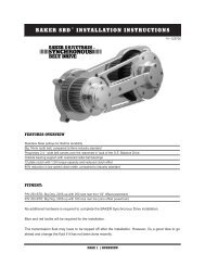
overviewtmThe BAKER 300 Wide Tire Kit, for Evo TM , is designed for use with all stock 1991-1999 Harley-Davidson ® Softail TM models. The BAKER 300 kit when installedwith the additional parts as listed effectively converts a Softail from a 5-speed,left side drive, stock rear tire motorcycle into a 6-speed, right side drive, fat tire custom.FEATURES6-speed transmission with DD6 RSD technologyThe BAKER RSD DD6 transmission provides smoother shifting, positive neutralfinding,and reduced cruising RPM on the highway as compared to the stock5-speed. With proven technology and helical 4th, 5th, and 6th gears, town andhighway cruising is noise-free. No disassembly of the stock 5-speed is required.Right Side DriveRight side drive is the critical variable in the equation of balancing a fat tire custommotorcycle. Left side drive fat tire motorcycles rely on offsetting (moving over) theengine, transmission, and/or the primary drive which moves the powertrain centerof-massto the left and creates an inherent balance bias to the left. Left turn andright turn body English is noticeably different with left side drive; not so with rightside drive.300 Series TireThe street look of a fat rear tire is the essential element of a custom Americanmotorcycle. The 300mm tire with it’s 12-inch wide stance has porn star caliber curbsideappeal with an aspect ratio that screams speed.PAGE | OVERVIEWV.5-<strong>060208</strong>
included partsParts Provided with the BAKER 300 KitSwingarm Assembly: Durable black and clearpowdercoated finish on swingarm and splash guard,heat treated 4140 steel 1” axle, and spherical pivotbearings.Rear Fender: Media blasted finished, heavy-duty13 gauge steel with 3/8” thick hidden internal struts.DD6 RSD Transmission Assembly:Polished, wrinkle black or silver finish complete withpulley, or 24 tooth chain sprocket optional, chromepulley cover/shroud, chrome cable ball ramp clutchactuator, or Hydraulic Actuator. Newly-designedBAKER billet top cover with hidden vent. No assemblyrequired. Speedometer recal box included.All necessary hardware: Note: Only oneof each part shown here. See Page 4 and 5 for quantitiesof each part.V.5-<strong>060208</strong>PAGE | PARTS
aker 300 included parts Detail3/4” - 16 x 5”Swingarm Pivot BoltPart # 15373(Qty. 1)Dog Leg SpacerPart # WT865(Qty. 1)1” Axle CollarPart # 99936(Qty. 2)Right Side Wheel Spacer(w/ belt applications only)Part # WT893P(Qty. 1)3/8” - 16 x 3”Dog Leg BoltPart # 37C300KSSPR(Qty. 2)WTK FenderPart # WT880(Qty. 1)3/8” - 24 x 1/4”Axle Adjustment Set ScrewPart # 37C25KKCS(Qty. 2)3/8” - 24 x 1-1/4”Axle Adjustment ScrewPart # 37125KKCS(Qty. 2)1/2” - 20 x 1-1/2”Fender-To-Frame BoltPart # 50150KBCPR(Qty. 2)Speedometer Recalibration BoxPart # 95E-56(Qty. 1)5/16-18-NylockPart # 37021(Qty. 4)3/8” - 16 x 1-1/2”Fender-To-Frame BoltPart # 37C150KBCPR(Qty. 4)1/2” AN-WasherFender-To-FramePart # 9900272(Qty. 2)Pivot Bolt Cover(Left and Right Side)Part # WT869C (Qty. 2)Comp SprocketPart # 158-56(Qty. 1)5/8-18 x 1”Grade 8 Axle Retaining BoltPart # 99618(Qty. 2)10-32 x 1/2”Right Pivot Cap Set ScrewPart # 73248R(Qty. 2)5/16-18 x 3/4”Part # 31C75KBCS(Qty. 4)3/8” - AN WasherFender WasherPart # AN960C616(Qty. 6)Chain Tensioner Assembly(Qty. 1)5/16” AN WasherPart # 6100(Qty. 4)Right Side Wheel Spacer(w/ chain applications only)Part # WT893P(Qty. 1)Right-Side Brake Bracketto Axle SpacerPart # WT905 (.320” - PM Wheels)Part # WT907 (.218” - Xtreme Wheels)(Qty. 1 ea.)Swingarm and Splashguard AssemblyPart #’s:WT881B/WT882B(Qty. 1)1/4” - 20 x 1”Ignition ModuleSocket Head Cap ScrewPart # 25C100KCSS/P(Qty. 2)PAGE | BAKER 300 V.5-<strong>060208</strong>
aker 300 included parts detailBrake Braket SpacerPart # WT906P (.590” for PM Wheels)Part # WT908P (.430” for XM Wheels)(Qty. 2)Seat Nut w/ ClipPart # 59768-97 (H-D)(Qty. 1)TransmissionRSD BAKER Direct Drive 6-SpeedPart # R701-DD6(Qty. 1)Axle CoverPart # WT854C(Qty. 2)Dog LegPart # WT857B(Qty. 1)1/4” - 20 x 1-1/4”Zinc-PlatedECM Socket Head Cap ScrewPart # 93207(Qty. 4)10 - 32 x 3/8”Axle Cover BoltPart # 10F37KBCPR(Qty. 4)1” AxlePart # WT859(Qty. 1)84-Pitch Primary ChainPart # 4282-84-56(Qty. 1)WTK Pulley CoverPart # WT858(Qty. 1)5/16” - 18 X 1½”Brake Bracket BoltPart # 31C150KCSPR(Qty. 2)Left Side Wheel Spacer(1.950”) Xtreme Machine: Part # WT894AP( 1.389”) Performance Machine: Part # WT904AP(Qty. 1 each)Pivot Tube SpacerPart # 99413(Qty. 2)V.5-<strong>060208</strong>PAGE | BAKER 300
parts Not includedADDITIONAL PARTS REQUIRED (NOT Provided with the BAKER 300 Kit)Rear Wheel with 300mm tire, pulley, and rotor: Any 10.5” wheel from Performance MachineForge-Tec or Extreme Machine is fully compatible with the BAKER 300 Wide Tire Kit. See the Contacts Directoryin the back of the installation manual for contact listings. Other wheel companies’ products may be compatible, but atthe time of this writing BAKER <strong>Drivetrain</strong> Engineering has only validated fitment of the aforementioned companies.Driveside Rear Brake System: The stock rear caliper and brake rotor is not compatible with the BAKER300. A Performance Machine driveside rear brake system (p/n 1284-00074A-1-CH) can be purchased directly fromPerformance Machine.Two Braided Steel Brake Lines and BanJo Fittings: Russell TM 28” and Russell TM 16” brake lines.Good Ridge TM rear brake switch “T” and 10mm #3 male 35º Banjo fitting (See page 8 for Rear Caliper Brake Checklistand page 24 for BAKER TM 300 Compatible Product Directory).Exhaust System: Right side drive compatible to date, BAKER Engineering has tested and validated fitment ofexhaust systems from several manufacturers. See the Directory of BAKER 300 TM Compatible Products on page 22.Rear Taillight/License Plate Assembly: We recommend taillights that will mount to the swingarm,footpeg, or derby cover like the ones shown below available from Drag Specialties.Example footpeg-mounted style Example swingarm mounted style Example derby cover styleHeritage Softail TM and Fat Boy SeatS (or any seats w/ side-mounted tabs): Because thesemodels utilize additional seat mounts on the side of the frame, the factory seats on the Heritage Softail TM and Fat Boyare not compatible with the BAKER 300 kit. See optional parts for factory seats that will work.OPTIONAL PARTS (RECOMMENDATIONS NOT Provided with the BAKER 300 Kit)Seat: Harley-Davidson ® offers a number of custom-styled contemporary seats like the ones shown in the H-D ® Partsand Accessories Catalog. The Stripper, Badlander TM and Sidekick are nicely styled and technically compatible withthe BAKER 300.Legend Air Ride System: An adjustable air suspension system for Softails , minor fabrication may be required.Front Wheel, Brake Rotor, and Caliper: To complete and finish off the BAKER 300 transformation,you may want to select a front wheel rotor and Performance Machine TM caliper assembly to compliment and match therear.PAGE | PARTSV.5-<strong>060208</strong>
SKILLs, KNOWLEDGE & TOOlsREQUIRED READINGIt is highly recommended that the following H-D ® publications are available for your reference as they are referred toin the instructions. Factory Service Manual for your year and model Factory Parts Manual for your year and model Genuine Parts and Accessories CatalogSkill LevelAs with most things in life, there is no substitute for skill and experience. We highly recommend that only a seasonedexperienced technician with an extensive background with Harley-Davidson ® motorcycles and the American customaftermarket successfully complete the BAKER 300 installation.SPECIALTY TOOLS PULLEY NUT SOCKET: Many tool boxes don’t have one of these. To make your life a bit easier, we make themother of all pulley nut sockets, which is made from one piece of bar stock and hard chrome plated for a super toughfinish. The throat of our wrench is deeper than other scokets to enable service work on right-side-drive and left-sidedrive5 & 6 transmissions. BAKER Part # TOOLD-56 Sawzall or cutoff wheel 1 3/16 ” socket (for clutch nut) 1 1/2 ” socket (for compensating sprocket nut)V.5-<strong>060208</strong>PAGE | SKILLS, KNOWLEDGE & TOOLS
checklistPrior to disassembly of your stock Softail to begin the BAKER 300transformation, it is recommended that the following checklist be utilized to makesure you have all the necessary parts to complete the job:BAKER 300 Wide Tire Kit Transmission Assembly Rear Fender Kit Swingarm and Hardware KitAdditional Parts (Not included with the kit) 10.5” wide rear wheel Avon TM or Metzeler TM 300 tire Rear wheel pulley, with bolts (for 1-1/8” Twincam belts) Rear wheel brake rotor, with bolts Driveside rear brake system : Performance Machine TM Caliper and Bracket p/n 1284-00074A-1 1-1/8” Twincam Softail TM drive beltRear caliper brake lines and fitting Available through Drag Specialties Russell SS DOT Brake Line 16” P/N 58362S Russell SS DOT Brake Line 26” W/CL P/N 58092S Drag Specialties 10MM BANJO BOLT P/N DS098109 Drage Specialties 10MM BANJO #3 MALE 35º P/N DS098150 Good Ridge Rear Brake Switch “T” P/N MCHD014 Drag Specialties 10MM BANJO #3 MALE 90º P/N DS098151 Exhaust system Exhaust seals Rear taillight/license plate assembly Transmission and primary oil Spectro Heavy Duty Platinum 6-Speed Transmission Lubricant--Spectro p/n R.HDPG6 andSpectro Heavy Duty Primary ChainCase Oil-Spectro p/n R.GAPCL DOT 5 brake fluid Seat (optional) Front wheel, brake rotor, and caliper (optional) Hydraulic Options: -3/8”-24 Banjo Bolt-10mm Banjo fitting- 11/16” Bore Clutch Lever Assembly- #3 Brake Line 530 Chain Final Drive (optional)PAGE | CHECKLISTSpectro DOT 5-Spectro p/n GABFV.5-<strong>060208</strong>
stock motorcycle disassemblyWith a completed BAKER 300 component checklist, disassembly of the stockSoftail can commence.1. Disconnect and removethe battery2. Drain Fluids: The transmission and primarydrive oils need to be completely drained. Refer tothe H-D® Factory Service Manual.3. Elevate the rear wheel off the groundby positioning the motorcycle on a suitable jack ormotorcycle lift. The motorcycle will remain in thisposition until the transformation from Page 9 toPage 20 is complete. So make sure it is safe, stableand there is 5-feet-or-so of peripheral room to moveabout.4. Disassemble: Remove the transmission,primary drive housing, clutch components, rear tire,swing arm, exhaust pipes, and rear fender. Refer tothe Factory Service Manual. Also, remove the rearbrake caliper and brake line all the way up to therear master cylinder. The primary drive componentswill be reinstalled as a part of the BAKER 300transformation.Figure 15. Cutting Fender Supports: The fenderstruts must be removed in order for the new BAKER300 TM fender to fit.Bolt into place the fender support cutting templates(marked L for left and R for right and provided in thekit) to the sides of the frame by using the bolts fromthe support covers. L and R must face out for correcttemplate orientation. Use a reciprocating saw (akasawzall) or abrasive cutoff wheel to remove thesupports as shown in Figure 2. With a large flatfile, break (smooth off) all sharp corners and edges.The resultant bare metal will not be visible once theBAKER 300 fender is installed.CHECK NEWLY CUT FRAME FOR FENDERFITMENT AT THIS POINT BEFOREPROCEEDING. Additional material may need tobe removed for proper fitment. As an anti-corrosionmeasure, paint the exposed bare metal with primerand/or paint.Cut fenderstrut alongtop edge oftemplateFigure 1Figure 2(Disassembly Continued on next page)V.5-<strong>060208</strong>PAGE | DISASSEMBLY
stock motorcycle disassembly(Disassembly Continued)7. Chasing the Threads on Frame: To aidin the assembly process use a tap and tap cuttingfluid to clean out the threads of the fender and dogleg attachment holes in the frame. figure 3. Usetap sizes:Tapped HolesTwo* 1/2”-20Six* 3/8”-16 1/2”-20 3/8”-16NOTE: The quantity of tapped holes in FIGURE 3to reflect the total amount on both sides.8. Final disassembly Checks: With thecompletion of the disassembly process, themotorcycle should look like Figure 4.Figure 3Figure 4PAGE 10 | DISASSEMBLYV.5-<strong>060208</strong>
BAKER 300 AssemblyWe highly recommend that the entire BAKER 300 Wide Tire Kit be installedand “mocked up” to validate fitment and function. After a successful mock up iscomplete, the BAKER 300 fender can be removed and painted to match the tankand front fender.Transmission:1. Pulley Cover: Remove the pulley coverand actuator assembly from the transmission. Setthe pulley cover and pulley aside for now. It willbe reinstalled towards the end of the assemblyprocess.2. Speed Sensor: Reinstall the stock speedsensor with spacer provided in kit for proper sensorto gear clearance and function. Figure 5 & 6.(.150” Thick)(STEPS CONTINUED ON NEXT PAGE)Figure 5Figure 6V.5-<strong>060208</strong>PAGE 11 | BAKER 300 ASSEMBLY
Transmission (CONTINUED):BAKER 300 Assembly3. Transmission Installation: Beforeinstalling transmission in the motorcycle placea piece of masking tape over both ends of themainshaft so that the clutch actuator rod does notfall out and become damaged. Install transmissionthrough the left side of motorcycle. Figure 8a.Gently maneuver transmission into positionFigure 7PAGE 12 | BAKER 300 ASSEMBLYV.5-<strong>060208</strong>
BAKER 300 AssemblySWING ARM:1. Splash Guard: Remove the splash guardfrom the BAKER 300 swing arm and set asidewith the provided hardware for later installation.2. Install Dogleg: Install BAKER 300 Doglegusing parts supplied in the kit:(1) Pivot Bolt Hex Head 3/4” - 16” x 5” QTY: 1(2) Chrome SHCS Bolts 3/8” - 16x3” QTY: 2Also use fender bolts for alignment of dogleg(1) 1/2” - 20 x 1 1/2 ”(2) 3/8” - 16 x 1 1/2 ”3. FIRST INSTALL 1 1/8 ” REAR DRIVE BELTAROUND THE TRANSMISSION: Installdogleg onto right side of frame. Slide pivot boltsupplied in kit with red thread lock and stock lockwasher, through the BAKER 300 dogleg. Installtwo 3/8”-16x3” bolts with blue thread lock. Installfender bolts loosley (just for alignment purposes).Make sure belt is in between dogleg. Figure 8.4. Install swingarm: Using the providedBAKER Pivot Tube and Swingarm Spacers, installthe swingarm. Remember that the swingarmspacers go between the pivot bearings andprovided, threaded pivot center tube. Use stockleft side pivot bolt and washers with red threadlock. Tighten both pivot bolts per Factory ServiceManual. Tighten bottom dogleg bolts to 21-31ft/lbs.Remove fender bolts.Figure 8Figure 9V.5-<strong>060208</strong>PAGE 13 | BAKER 300 ASSEMBLY
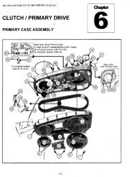
BAKER 300 AssemblyPRIMARY:Counter bore side of coupler facing outward1. Shifter Linkage Arm: Install forward controlfactory shifter linkage to transmission shifter arm.2. Inner Primary: Install inner primary perservice manual. After installing inner primary, shifttransmission by hand through the gears to makesure linkage will not hit the inside of the innerprimary.3. Tranmission: Tighten transmission bolts perService Manual4. Starter: Bolt to inner primary per FactoryService Manual. FIGURE 10.5. DD6 Chain Tensioner AnchorPlate: Install chain tensioner assembly (providedin kit) figure 11 (removal of anchor plate isnecessary to install new tensioner nut. Use redthread lock and torque anchor plate to 12-14 ft-lb.or 16.3-19.0 nm.)6. DD6 Chain Tensioner Shoe: Installtensioner shoe and bolt in place loosely at thistime.7. Primary Chain & Clutch Basket: Installcompensating sprocket, chain, and clutch basket.(compensating sprocket and chain provided inkit.) (Do not use thread lock at this time.) Torquecompensating sprocket and clutch basket nut perFactory Service Manual. Tighten chain as tight asyou can.Figure 10(PRIMARY assembly continued onnext page)Figure 11Figure 12PAGE 14 | BAKER 300 ASSEMBLYV.5-<strong>060208</strong>
BAKER 300 AssemblyPRIMARY assembly (CONTINUED):8. Primary Chain Alignment: Perform asprocket alignment check at this time. Refer toFactory Service Manual. (A different thicknesswasher may be required for proper alignment ofprimary chain. Which can be purchased at yourlocal Harley Davidson ® dealer) Once verificationof correct alignment has been verified loosenprimary chain, remove compensating sprocket nutand clutch basket nut. Apply (red) thread lock tocompensating sprocket nut and clutch basket nutand torque to factory specifications.9. Chain Adjustment: Remove chain tensionerbolt and apply (red) thread lock, adjust chain perservice manual, and torque to 21-29 ft-lbs. figure13.10. Outer Primary: Install outer primary perservice manual.11. Oil Tank: Install oil tank and lines per FactoryService ManualFigure 13Figure 14Figure 15V.5-<strong>060208</strong>PAGE 15 | BAKER 300 ASSEMBLY
BAKER 300 AssemblyFRAME COMPONENTS:1. Rear Brake Line: Install brake lines, fittings,and brake switch from rear master cylinder to theswing arm. (Running the brake line along the frameas the original was located. Use a 16” flexible brakeline from the master cylinder to brake light switch‘T’. Use a 26” flexible line from brake ‘T’ to rearcaliper. Routing the line through the swing arm tolater be placed in the ‘notch’ in the provided BAKER300 splashguard.2. Speedometer Re-Calibration:Install the provided speedometer re-calibrationbox between to the speed sensor harness and thespeed sensor. (See Re-cal box for instructions andadjustment info.) figure 164. SplashGuard: Reinstall splash guard withthe provided hardware making sure to route therear brake line through the notch in the bottom rightof the splash guard. Torque to 220 in-lbs.Figure 16PAGE 16 | BAKER 300 ASSEMBLYV.5-<strong>060208</strong>
BAKER 300 AssemblyPULLEY COVER and fluids:1. Mechanical Clutch ActuatorCover: Remove outer mechanical actuator coverwith gasket from chrome pulley cover. Install stockclutch cable through chrome actuator cover. (Do notover tighten clutch cable to actuator cover) Hookcable end to ball and ramp assembly. Put a liberalamount of grease around the ball and rampa andferal. Make sure you seat ball and ramp properly inactuator cover. Figure 17.2. Hydraulic Clutch Actuator CoverThe Hydrualic Clutch will arrive with the gasketand bolts in place, torqued to 110 in-lbs with bluethread lock. The o-rings around the piston arealready lubed and it is ready to be bolted to thetransmission bearing door along with the pulleycover. The actuator can be bleed in the mannersimilar to the brakes and the hydraulic fluid port isdesigned for use with a 3/8”-24 Banjo Bolt and Dot5 brake Fluid Spectro P/N-GABF.3. Pulley Cover: Apply (blue) thread lock topulley cover bolts and then reinstall pulley cover.Torque the bolts to 200 in-lbs. (3pc 5/16-18x1”Bolts). Apply (blue) thread lock to actuator coverbolts and reinstall actuator cover with gasket tochrome pulley cover. Torque to 110 in-lbs.4. Clutch Adjustment: Adjust clutch andclutch cable per Factory Service Manual.5. Primary Fluid: Fill primary fluid per servicemanual.6. Transmission Fluid: Fill transmission fluidwith 20-24 fluid oz of gear oil.BAKER recommendsSpectro Heavy Duty Platinum 6 speed transmissionfluid Spectro P/N- R.HDPG67. Engine Oil: Add engine oil per service manual.Figure 17Figure 18V.5-<strong>060208</strong>PAGE 17 | BAKER 300 ASSEMBLY
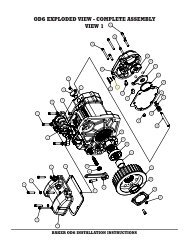
BAKER 300 AssemblyREAR WHEEL:1. Brake Caliper: Install Performance Machine ®drive side brake caliper on rear wheel brake rotor.(HOLD CALIPER CAREFULLY NOT TODAMAGE WHEEL OR BRAKE ASSEMBLYDURING INSTALLATION)2. Right Wheel Spacer: Install provided rightside wheel spacer in preparation for bolting on BAKER300 driveside brake bracket.3. Rear Wheel: Install rear wheel into the swing armwith provided left side wheel spacer and the BAKER300 driveside brake bracket axle spacer provided inthe kit. Make sure to first get the drive belt ‘over’ thepulley before the wheel assembly is fully in place. SEEFIGURE 20 for spacers and Figure 19for exploded view diagram.4. Rear Wheel Axle: Cover the provided BAKER300 axle with bearing grease or anti-seize as a rustinhibitor and assembly aid.5. Brake Bracket Bolts: Apply (blue) threadlock to provided brake bracket bolts and finger tightbrake bracket to swing arm at this time being sure touse the provided bolt spacer between to the bracket andthe swing arm tabs. FIGURE 22A6. Axle Bolts: Apply (red) thread lock to axle boltsand put in place with the provided hardened steel axlecollars. Do not fully tighten at this time in preparation forwheel and belt tracking adjustments.7. Rear Wheel Alignment: Adjust rear belt tensionand wheel alignment with the provided set screwsalready installed in the BAKER 300 swingarm, perFactory Service Manual. Make sure to spend the time tospin the rear tire by hand to fully ensure that the belt istracking straight on the motorcycle.FAILURE TO DO THIS COULD RESULT INBRAKE ASSEMBLY DAMAGE, REAR PULLEYDAMAGE, TRANSMISSION PULLEY DAMAGE,OIL TANK DAMAGE, A BROKEN AND/ORDAMAGED BELT , AND/OR PERSONALINJURY!8. Torque Bolts: Torque axle bolts to 40-45 ftlb.Torquebrake bracket bolts to 220 in-lbs. Installstainless axle set screws with (blue) thread lock (snug).9. BAKER <strong>Drivetrain</strong> TM Axle Covers: Installrear axle covers provided in kit. Apply (blue) thread lockto the provided axle cover bolts before installing.Left side spacerChain right-side spacerFront of motor-Figure 20Brake bracketspacersBelt right-sidespacerPAGE 18 | BAKER 300 ASSEMBLYV.5-<strong>060208</strong>
BAKER 300 Assemblyfigure 20DescriptionP/N1. 8-32 x 3/8” Axle Cover Bolt 10F37KBCPR2. Axle Cover WT8543. 3/8” - 16 x 1” Grade 8 Axle Reatining Bolt 1151054. 1/8 “ Axle Washer 10705-025745. Swing Arm WT8916. Performance Machine Brake Bracket Axle Spacer WT9059Xtreme Machine Bracket Axle SpacerWT9077. 1” Axle WT8598. Right Side Wheel Spacer (Belt) WT893Right Side Wheel Spacer (Chain)WT8989. Drive Side Brake Bracket -----10. Performance Machine Brake Bracket Spacer WT906Xtreme Machine Brake Bracket SpacerWT90811. Caliper Bolts (Wheel Company Provided) -----12. 3/8” -16 x 1/4” Axle Adjustment Set Screw 37C25KKCPR13. 3/8” - 16 x 1-1/4” Axle Adjustment Screw 13515114. 5/16” - 18 x 1-1/4” Brake Bracket Bolt 31C150KCSPR15. Left Side Wheel Spacerfor Xtreme Machine WheelsWT894A16. Left Side Wheel Spacerfor Performance Machine WheelsWT904AV.5-<strong>060208</strong>PAGE 19 | BAKER 300 ASSEMBLY
BAKER 300 AssemblyBAKER 300 Rear Fender:1. Rear Fender: Install fender by sliding the rightside over the dogleg and the left mounting flangeflush with the side of the frame. Figure 21 Usingbolts provided, apply (blue) thread lock (four 3/8-16x11/2, four 3/8 AN washers, two ½-13x11/2,and two ½ an washers) and torque to 21-31 ft-lbs.2. Engine Module: Install ignition module onrear fender with bolts provided, two ¼”-20x1”(Ignition Module only), four ¼” an washers, and four¼” nylock nuts) Torque to 8-10 ft-lbs. Install seat nutwith clip.3. BAKER 300 Pivot Caps: Install pivot capsusing (blue) thread lock on pivot cap set screws.The pivot cap with the ‘sleeve’ inside of it is for useon the 5/8-11 bolt head on the right side.4. Ignition Harness: Hook up ignition moduleto factory wiring harness per Factory ServiceManual. Figure 22Figure 21Figure 22PAGE 20 | BAKER 300 ASSEMBLYV.5-<strong>060208</strong>
BAKER 300 AssemblyFINISH LINE:1. Rear Brake Line: Route brake line to rearcaliper along inside of swing arm. figure 23MAKE SURE THAT REAR BRAKE LINEWILL NOT CONTACT BELT IN ANYWAYTAKING INTO ACCOUNT BELT SLAPWHILE RIDING.2. Bleed Brakes: Bleed rear brakes per FactoryService Manual.3. Exhaust: Install exhaust gaskets that arecompatible with your exhaust. Install exhaustsystem of your choice. Take the time to make surethat the exhaust is in full contact with the gasket atthe cylinder head and that the exhaust has ampleclearance to all parts of the motorcycle. Referto Factory Service Manual on exhaust flange tocylinder head torque specifications.4. Battery: Install the battery.5. Seat: Install the seat of your choice using theprovided seat nut.6. CHECK ALL BOLTS AND FLUIDS BEFORESTARTING MOTORCYCLE FOR YOURPERSONAL SAFETY AND FOR THEMECHANICAL INTEGRITY OF YOURMOTORCYCLE!Figure 23This completes the transformation ofyour SICK new Softail with the BAKER 300 Wide Tire Kit.V.5-<strong>060208</strong>PAGE 21 | BAKER 300 ASSEMBLY
directory of compatible productsBAKER 300 compatible exhaust pipesEddie Trotta TMThunder Cycles TMmartin brothers TMtrendkillrs rsd TMR&D Note: Modified exhaustbracketmartin brothers TMskirtlifters TMR&D Note: Will not work withfloorboardswest coast choppers TMfu pipesODDI TMnASTY pUFFERS TmBAKER <strong>Drivetrain</strong>9804 E. SaginawHaslett, MI 488401-877-640-2004www.bakerdrivetrain.comDrag Specialties1-608-758-1111www.dragspecialties.comEddie Trotta’s Thunder Cycle Design1-954-763-2100www.thundercycle.comHarley Davidson Motor Company ®1-414-343-4056www.harley-davidson.comMartin Bros Motorcycles1-972-709-2552www.martinbrosmotorcycles.comPerformance Machine Inc.1-800-479-4037www.performancemachine.comWest Coast Choppers ®1-562-983-6666www.westcoastchoppers.comXtreme Machine1-217-291-0200www.xtrememachineusa.comLegend Air Suspension Systems1-605-737-4200www.legend-airride.comForge-Tec1-866.509.0557http://www.forge-tec.com/Oddi Cycles1-203-281-9619www.oddicycles.comPAGE 22 | DIRECTORYV.5-<strong>060208</strong>
termsSPECIAL ORDERSA minimum $500 deposit is required with all special orders. Special orders include unique case finishes, unique side door requests(ie; wrinkle black door or no logo).ALL OTHER ORDERSOrders can be pre-paid using VISA, Mastercard or American Express.Prices shown are F.O.B. Haslett, MI. BAKER TM provides free UPS ground shipping on all retail orders for complete transmissions ortransmission kit. UPS air shipment is available upon request. Customer is responsible for air shipment premiums.LIMITED WARRANTYBAKER TM Inc. transmission assemblies, transmission kits, and wide tire kits are guaranteed to the original purchaser to be free ofmanufacturing defects in materials and workmanship for a period of 2years/24,000 miles - whichever is sooner for the kit and 5years/50,000 miles - whichever is sooner for the transmission.If the product is found by BAKER TM to be defective, such products will, at the option of BAKER TM , be replaced or repaired at cost toBAKER TM .In the event warranty service is required, the original purchaser must call or write BAKER TM immediately with the problem.If it is deemed necessary for BAKER TM to make an evaluation to determine whether the transmission assembly or transmission kitis defective, the entire transmission assembly, whether originally purchased as an assembly or kit, must be properly packaged andreturned prepaid to BAKER TM with a copy of the original invoice of purchase.If after an evaluation has been made by BAKER TM and a defect in materials and/or workmanship is found, BAKER TM will, at BAKER’soption, repair or replace the defective part of the assembly.Warranty card must be returned within 45 days of purchase to be valid.ADDITIONAL WARRANTY PROVISIONSThis limited warranty does not cover labor or other costs or expenses incidental to the repair and or replacement ofBAKER TM products. This warranty does not apply if one or more of the following situations is judged by BAKER TMto be relevant: improper installation, accident, modification (including but not limited to use of unauthorized parts),racing, high performance application, mishandling, misapplication, neglect (including but not limited to impropermaintenance), or improper repair.BAKER TM shall not be liable for any consequential or incidental damages arising out of or in connection with aBAKER TM transmission assembly, transmission kit, swingarm, fender, component or part. Consequential damagesshall include without limitation, loss of use, income or profit, or losses sustained as the result of injury (includingdeath) to any person or loss of or damage to property.BAKER TM transmissions, transmission kits, and Wide Tire Kits are designed exclusively for use in Harley-Davidson ®motorcycles. BAKER TM shall have no warranty or liability obligation if a BAKER TM part is used in any otherapplication.If it is determined that a BAKER TM transmission assembly has been disassembled during the warranty period for anyreason, this limited warranty will no longer apply.V.5-<strong>060208</strong>PAGE 23 | TERMS
disclaimerThe words Harley, and H-D are registered trademarks and are for reference only. Use of H-D model designations andpart numbers are for reference only. BAKER <strong>Drivetrain</strong> has no association with, and makes no claim against, thesewords, trademarks, or companies.It is the sole responsibility of the user to determine the suitability of this product for his or her use, and the usershall assume all legal, personal injury risk and liability and all other as well as all other obligations, duties and risksassciated therewith.customer supportFor any installation or service questions, please contact our BAKER TM 300 technical department toll free: 1-877-640-2004.PAGE 24 | DISCLAIMERV.5-<strong>060208</strong>