Shaping Axis-Symmetric Dual-Reflector Antennas by Consecutively ...
Shaping Axis-Symmetric Dual-Reflector Antennas by Consecutively ...
Shaping Axis-Symmetric Dual-Reflector Antennas by Consecutively ...
- No tags were found...

Create successful ePaper yourself
Turn your PDF publications into a flip-book with our unique Google optimized e-Paper software.
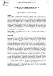
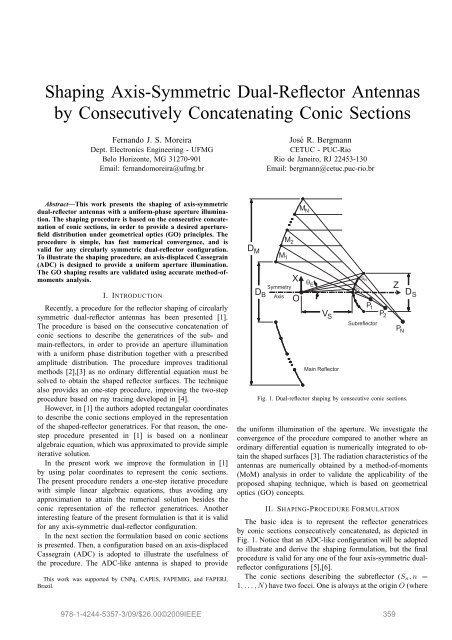
Gain (dBi)504540353025ClassicalShapedRMS Error (λ)0.040.0350.030.0250.020.0150.01RMS error of subreflector shaped with differential equationRMS error of subreflector shaped with conic sectionsRMS error of main−reflector shaped with differential equationRMS error of main−reflector shaped with conic sections200.0051510−3 −2 −1 0 1 2 3θ (degrees)Fig. 4. E-plane radiation patterns of the classical (dashed lines) and shaped(solid lines) ADC’s. <strong>Reflector</strong>s shaped with ∆θ F ≈ 10 −4 × θ E .0−0.005−4 −3.5 −3 −2.5 −2 −1.5log( ∆θ F/θ E)Fig. 5. RMS error of the shaped reflector surfaces as function of ∆θ F .is the same adopted in [1]:G F (θ F ) = cos 2p (θ F /2)/r 2 F , (26)with p = 83 to provide −25 dB taper at θ F = θ E [1]. Theshaped reflector generatrices are plotted with solid lines inFig. 3 together with the shaped subreflector caustic.Both classical and shaped antennas, fed <strong>by</strong> the feed modelof (26), were analyzed <strong>by</strong> a MoM technique. The radiationpatterns in the E-plane are depicted in Fig. 4. As expected,the gain of the shaped antenna (49.28 dBi) is higher that thatof the classical configuration (47.65 dBi). The side-lobe levelsof the shaped antenna are also higher (about 7 dB) than thoseof the classical configuration, as expected.The shaping procedure of Sect. II is simpler and, consequently,faster than traditional procedures based on thenumerical integration of ordinary differential equations [2],[3].Another important feature is the numerical convergence ofthe present procedure, which provides the same accuracyof traditional procedures with ∆θ F steps about 1000 timesbigger. To illustrate this, Fig. 5 presents the RMS error of theshaped reflector surfaces as function of ∆θ F . The referencesurfaces are obtained from a traditional shaping procedure [3]with a very small ∆θ F value (∆θ F ≈ 10 −4 × θ E ). TheRMS errors of the shaped subreflectors were obtained <strong>by</strong>comparing the values of r F (i.e., the distance from O to thesubreflector) with those of the reference subreflector. For themain reflectors, the comparisons were made with the Cartesianz coordinates. From Fig. 5 one observes that the shapingprocedure of Sect. II sustains very small RMS errors evenfor ∆θ F ≈ θ E /50 (i.e., with approximately N = 50 conicsections representing each reflector surface).As both shaping procedures (based on differential equationsor conic sections) are iterative processes, the surface errortends to increase as θ F → θ E (i.e., at the reflector rims).Figure 6 shows the maximum error (at the reflector rims) asfunction of ∆θ F . By comparing Figs. 5 and 6 one observesthat both errors have approximately the same convergenceMaximum Error (λ)4 x 10⁻³ Maximum error at subreflector rim with differential equationMaximum error at subreflector rim with conic sections3.5Maximum error at main−reflector rim with differential equationMaximum error at main−reflector rim with conic sections32.521.510.50−4 −3.5 −3 −2.5 −2 −1.5log( ∆θ /θ ) F EFig. 6. Maximum error (at the reflector rims) of the shaped reflector surfacesas function of ∆θ F .behavior (i.e., the RMS error is actually dominated <strong>by</strong> themaximum error at the reflector rims).REFERENCES[1] Y. Kim and T.-H. Lee, “Shaped Circularly <strong>Symmetric</strong> <strong>Dual</strong> <strong>Reflector</strong><strong>Antennas</strong> <strong>by</strong> Combining Local Conventional <strong>Dual</strong> <strong>Reflector</strong> Systems,”IEEE Trans. <strong>Antennas</strong> Propagat., vol. 57, no. 1, pp. 47–56, Jan. 2009.[2] V. Galindo, “Design of dual-reflector antennas with arbitrary phase andamplitude distributions,” IEEE Trans. <strong>Antennas</strong> Propagat., vol. AP-12,no. 4, pp. 403–408, July 1964.[3] J. J. Lee, L. I. Parad, and R. S. Chu, “A shaped offset-fed dual-reflectorantenna,” IEEE Trans. <strong>Antennas</strong> Propagat., vol. AP-27, no. 2, pp. 165–171, Mar. 1979.[4] J. Hakli, J. Ala-Laurinaho, and A. V. Raisanen, “Numerical synthesismethod for designing a shaped dual reflector feed system,” Proc. Inst.Elect. Eng. Microw. <strong>Antennas</strong> Propag., vol. 152, no. 5, pp. 311-318, Oct.2005.[5] S. P. Morgan, “Some examples of generalized Cassegrainian and Gregorianantennas,” IEEE Trans. <strong>Antennas</strong> Propagat., vol. AP-12, no. 6,pp. 685-691, Nov. 1964.[6] F. J. S. Moreira and Aluizio Prata, Jr., “Generalized classical axiallysymmetric dual-reflector antennas,” IEEE Trans. <strong>Antennas</strong> Propagat.,vol. 49, no. 4, pp. 547–554, April 2001.[7] B. S. Westcott, F. A. Stevens, and F. Brickell, “GO synthesis of offsetdual reflectors,” IEE Proc., Pt. H, vol. 128, no. 1, pp. 11–18, Feb. 1981.2009 SBMO/IEEE MTT-S International Microwave & Optoelectronics Conference (IMOC 2009) 362