SG-E60 & SG-E70 Tool Manual (PDF) - StoneAge Inc
SG-E60 & SG-E70 Tool Manual (PDF) - StoneAge Inc
SG-E60 & SG-E70 Tool Manual (PDF) - StoneAge Inc
- No tags were found...

You also want an ePaper? Increase the reach of your titles
YUMPU automatically turns print PDFs into web optimized ePapers that Google loves.
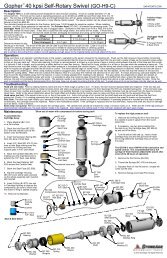
GEARBOX DRIVEN POWERED ROTATION<strong>SG</strong>-60 and <strong>SG</strong>-70OPERATION AND MAINTENANCEMANUAL54 Girard St. Durango, Colorado 81303 (970) 259-2869 Phone (970) 259-2868 Faxwww.stoneagetools.com sales@stoneagetools.com04/06
TABLE OF CONTENTS1.0 INTRODUCTION2.0 SAFETY WARNING3.0 DESCRIPTION4.0 PARTS LIST5.0 ASSEMBLY DRAWINGS6.0 WARRANTYAPPENDIXAir MotorHydraulic Motor<strong>SG</strong> Swivel <strong>Manual</strong>1.0 INTRODUCTIONThis manual was prepared to provide the operator with the basic information needed to operate and service thisequipment. The operating recommendations in the manual will insure that you receive satisfactory performance.All operating personnel responsible for the care of this equipment should be familiar with the information in thismanual.If you have any questions or problems with this equipment, please contact the distributor you obtained the productfrom, or the manufacturer:<strong>StoneAge</strong>, <strong>Inc</strong>.54 Girard St.Durango, CO 81303(970) 259-2869Fax (970) 259-2868www.stoneagetools.com2.0 SAFETY WARNINGOperations with this tool can be potentially dangerous if caution is not exercised prior to and during tool use.Please read and follow all of these instructions.2.1 Only competent and trained persons should operate this equipment.2.2 Do not exceed the maximum operating pressure specified for any component in a system.2.3 This equipment should always be used with an operator controlled dump mechanism to releasethe high pressure water.2.4 The immediate work area should be marked off to keep out untrained persons.2.5 All personnel in the area should wear eye protection, and other protective clothing in accordancewith specific conditions.2.6 The tool should be securely supported. Strong thrust is created by waterjets and these forcescan become unbalanced if a nozzle should become plugged.2.7 Inspect the equipment for visible signs of deterioration, damage, or improper assembly. Do notoperate until repaired. Make sure all threaded connections are tight and leak free.2.8 Check to see that all control functions work properly before going to high pressure.2.9 If it is necessary to have a person work near the cleaning jets, then it is this person who shouldhave control of the pressure dump mechanism.
3.0 DESCRIPTIONThe <strong>SG</strong>-60/70 is designed for waterblast cleaning applications. It is capable of flow rates to 80 gpm at pressuresup to 20,000 psi. It can be used with a variety of nozzle head designs for many different applications. Rotation ofthe nozzles provides uniform coverage over a large area.The <strong>SG</strong> water swivel has a single high pressure seal that is long lasting and easy to service. The <strong>SG</strong>-P12KMGmodel has 3/4 NPT inlet, and is rated up to 15 ksi. The <strong>SG</strong>-M12KMG model has a 3/4 Medium Pressure inlet, andis rated up to 20 ksi. Both types of swivel are capable of up to 80 gpm.Two reduction gearbox options are available. The 18:1 ratio provides a speed range of 30 to 180 rpm; the 60:1ratio provides a speed range of 10 to 50 rpm.The <strong>SG</strong>-60 is powered by an air motor and reduction gearbox. The rotation speed is variable and can becontrolled with a valve in the inlet or exhaust air line.The <strong>SG</strong>-70 is powered by a hydraulic motor and reduction gearbox. The rotation speed is variable and can becontrolled with a valve in the inlet hydraulic line.4.0 PARTS LIST<strong>SG</strong>-60 Air PoweredBR 155 Muffler 1CB 114 Inlet Fitting 1CST 130 Hose 1GP 057 Lubricator 1HF 033-A Torque Clamp 1LM 016-4 Air Motor 1<strong>SG</strong> 031 Retaining Ring 2<strong>SG</strong> 150-60 Gearbox, 60:1 1*<strong>SG</strong> 150-18 Gearbox, 18:1 1*<strong>SG</strong>-xxKMG-x Swivel 1SM 132-3 Torque Arm 1<strong>SG</strong>-70 Hydraulic PoweredHF 033-A Torque Clamp 1LM 120 Adapter Plate, Hyd. 1LM 122 Hydraulic Motor 1LM 123 Fitting, Hydraulic 2<strong>SG</strong> 031 Retaining Ring 2<strong>SG</strong> 150-60 Gearbox, 60:1 1*<strong>SG</strong> 150-18 Gearbox, 18:1 1*<strong>SG</strong>-xxKMG-x Swivel 1SM 132-3 Torque Arm 1
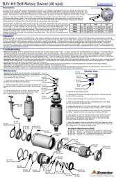
<strong>SG</strong>-60 EXPLODED ASSEMBLY DRAWINGCB 114Inlet FittingGP 057Lubricator<strong>SG</strong> P12 KML or <strong>SG</strong> A12 KMLSwivelCST 130HoseBR 155MufflerSM 132-3Torque ArmHF 033-ATorque ClampLM 016-4Air Motor<strong>SG</strong> 150-60 or <strong>SG</strong> 150-18Gearbox<strong>SG</strong> 031Retaining Ring (2)06/06
<strong>SG</strong>-70 EXPLODED ASSEMBLY DRAWINGLM 122Hydraulic MotorLM 123Hydraulic Fitting (2)<strong>SG</strong> P12 KML or <strong>SG</strong> A12 KMLSwivelSM 132-3Torque ArmLM 120Adapter PlateHF 033-ATorque Clamp<strong>SG</strong> 150-60 or <strong>SG</strong> 150-18Gearbox<strong>SG</strong> 031Retaining Ring (2)06/06
6.0 LIMITED WARRANTY<strong>StoneAge</strong>, <strong>Inc</strong>. Warrants to the extent herein provided the products of its own manufacture against defects inmaterial and workmanship under normal use and service for which the products were designed for a period of six(6) months after shipment from the factory. If such products should fail through defect in workmanship or materialand specific written notice of failure is made within six (6) months after date of shipment from the factory,<strong>StoneAge</strong>, <strong>Inc</strong>. will either repair or replace any such items, F.O.B. its factory without charge. <strong>StoneAge</strong>, <strong>Inc</strong>.shall not be liable for expense incurred in repairs or alterations made outside the factory without the proper andprior authorization. <strong>StoneAge</strong>, <strong>Inc</strong>. shall have the option of requiring the return of the defective products to itsfactory, with transportation charges prepaid, to establish the claim. <strong>StoneAge</strong>, <strong>Inc</strong>. shall in no event be heldliable for damages or delay resulting from or arising out of defective products nor for consequential damages orotherwise except for repair or replacement of items of defective material or workmanship as foresaid.THIS WARRANTY IS EXPRESSLY IN LIEU OF ALL OTHER WARRANTIES EXPRESSED OR IMPLIEDINCLUDING THE WARRANTIES OF MERCHANTIBILITY AND FITNESS FOR USE AND NEITHER ASSUMES,NOR AUTHORIZES ANY PERSON TO ASSUME FOR STONEAGE, INC. ANY OTHER LIABILITY INCONNECTION WITH THE SALE OF ITS PRODUCTS. THIS WARRANTY SHALL NOT APPLY TO PRODUCTSOR ANY PARTS THEREOF WHICH HAVE BEEN SUBJECT TO ACCIDENT, NEGLIGENCE, ALTERATION,ABUSE, OR MISUSE. STONEAGE, INC. MAKES NO WARRANTY WHATSOEVER IN RESPECT TOACCESSORIES, PARTS OR PRODUCTS NOT MANUFACTURED BY STONEAGE, INC.
PART NO. 45-200 D170PL (Rev. D)AM SERIES LUBRICATED AIR MOTORSOPERATION & MAINTENANCE MANUALModel 2AM ShownModel 4AM ShownModel 6AM ShownModel 16AM ShownThank you for purchasing this Gast product. It is manufactured to the highest standardsusing quality materials. Please follow all recommended maintenance, operationaland safety instructions and you will receive years of trouble free service.IMPORTANT: PLEASE READ THIS MANUAL AND SAVE FOR FUTURE REFERENCE.General information• Clearances: Model Total End Clearance (in/mm) Top Clearance (in/mm)1AM/1 UP 0.00020/0.0508 0.0015/0.03812AM 0.00025/0.0635 0.0015/0.03812AM * 0.00025/0.0635 0.0025/0.06354AM 0.00035/0.0889 0.0015/0.03814AM * 0.00035/0.0889 0.0025/0.06356AM 0.00035/0.0889 0.0015/0.03818AM 0.00048/0.1219 0.0015/0.038116AM 0.00060/0.1524 0.0015/0.0381* Models with the last three digits greater than 500 (ie 2AM XXX-501)• Vane Life:• Operating Pressure:Depends upon speed, operating pressure and motor maintenance.100 psi or below (7 bar)Product Use Criteria:• Operate at temperature up to 250ºF (121ºC).• Protect unit from dirt and moisture.• Use ONLY compressed air to drive motor.• Air lines connected to motor should be the same size orthe next size larger than the intake port for efficientoutput and speed control.• Protect all surrounding items from exhaust air.• Bearings are grease packed.• Use Gast #AD220 or a detergent SAE#10 automotiveengine oil for lubricating.ISO 9001 & 14001 CERTIFIEDwww.gastmfg.com®Registered Trademark/Trademark of Gast Manufacturing <strong>Inc</strong>., Copyright ©2001 Gast Manufacturing <strong>Inc</strong>. All Rights Reserved.
LubricationUse Gast #AD220 or a detergent SAE #10 automotiveengine oil for lubricating. Lubricating is necessary toprevent rust on all moving parts. Excessive moisture inthe air line may cause rust or ice to form in the mufflerwhen air expands as it passes through the motor.Install a moisture separator in the air line and an aftercooler between compressor and air receiver to helpprevent moisture problems.<strong>Manual</strong> LubricationShut the air motor down and oil after every 8 hours ofoperation. Add 10-20 drops of oil to the air motor intakeport.Automatic LubricationAdjust inline oiler to feed 1 drop of oil per minute forhigh speed or continuous duty usage. Do Not overfeedoil or exhaust air may become contaminated.Check intake and exhaust filters after first 500 hours ofoperation. Clean filters and determine how frequentlyfilters should be checked during future operation. Thisone procedure will help assure the product’sperformance and service life.FlushingFlushing this product to remove excessive dirt, foreignparticles, moisture or oil that occurs in the operatingenvironment will help to maintain proper vaneperformance. Flush the motor if it is operating slowly orinefficiently.Use only Gast #AH255B Flushing Solvent. DO NOTuse kerosene or ANY other combustible solvents toflush this product.1. Disconnect air line and muffler.2. Add flushing solvent directly into motor. If usingliquid solvent, pour several tablespoons directlyinto the intake port. If using Gast #AH255B, spraysolvent for 5-10 seconds into intake port.3. Rotate the shaft by hand in both directions for afew minutes.4. You must wear eye protection for this step.Cover exhaust with a cloth and reconnect the airline. Slowly apply pressure until there is no traceof solvent in the exhaust air.5. Listen for changes in the sound of the motor. Ifmotor sounds smooth, you are finished. If motordoes not sound like it is running smoothly,installing a service kit will be required.(See “Service Kit Installation”).Check that all external accessories such as reliefvalves or gauges are attached and are not damagedbefore operating product.ShutdownIt is your responsibility to follow proper shutdownprocedures to prevent product damage.1. Turn off air intake supply.2. Disconnect plumbing.3. Remove air motor from connected machinery.4. Wear eye protection. Keep away from airstream.Use clean, dry air to remove condensation.5. Lubricate motor with a small amount of oil inchamber. Rotate shaft by hand several times.6. Plug or cap each port.7. Coat output shaft with oil or grease.8. Store motor in a dry environment.SERVICE KIT INSTALLATIONGast will NOT guarantee field-rebuilt productperformance. For performance guarantee, theproduct must be returned to a Gast authorizedservice facility.Service kit contents vary. Most contain vanes, end capgasket, body gasket, bearings and a muffler element orfelt.Major and Minor Rebuilds<strong>Tool</strong> kits which include a more in-depth rebuildmanual are available through your Gast distributor.These kits include the tools required to remove andreassemble end plates, bearings and shaft seals, and toset the proper end clearance. The rebuild manual alsoincludes step by step instructions, including illustrations,to help achieve a successful rebuild. GastManufacturing, <strong>Inc</strong>. highly recommends using the airmotor rebuild manual and tool kit when attempting aminor or major rebuild to your Gast air motor.Minor Rebuild:1. Remove the end cap.2. Remove dead end plate bolts.3. Remove dead end plate. (Use factory issued tool,do not use screwdriver to remove the end plate.4. Remove the dowel pins from the body and pushback into end plate until flush or just below themachined surface of the end plate.5. Remove vanes.6. Clean parts. Check for scoring on the end plateand rotor assembly. If scoring exists, send unit toa Gast authorized service facility.7. Lubricated models only: Lightly oil and reinstallvanes.8. Place the proper end plate gasket on the endplate. If the original is damaged, replace with anew one supplied in the Service Kit.9. Place the dead end plate on the body.10. Press the bearing onto the shaft using a factorysupplied bearing pusher.11. Tap dowel pins into body and install end platebolts. Tighten bolts to 75-100 in-lbs.12. Set end clearance as required by model:1AM-4AM and NL22-NL52 models - use thebearing taper from kit to lightly tap on inner race ofthe dead end bearing to free up and center therotor in the body.6AM-8AM models - lightly strike the drive endshaft with a soft hammer to push the rotor awayfrom the drive end plate. The rotor must NOT rubon either end plate.13. Reattach end cap.14. If the air motor is lubricated, apply a few dropsof Gast #AD220 lubricant into ports. Rotate shaftby hand for a few rotations.Major Rebuild:1. Remove the end cap.2. Remove dead end plate bolts.
3. Remove dead end plate. (Use factory issued tool,do not use screwdriver to remove the end plate.)4. Remove the dowel pins from the body and pushback into end plate until flush or just below themachined surface of the dead end plate.5. Remove rotor using an arbor press.6. Remove vanes and ejection mechanism ifreversible. (Ejection mechanisms may consist ofvane springs, pins, caps or cam rings.)7. Remove shaft seal and bearings from drive endplate and bearing from dead end plate. (Usefactory issued tool.)8. Do Not remove drive end plate bolts or drive endplate.9. Clean parts. Check for scoring on the end platesand rotor assembly. If scoring exists, send unit toa Gast authorized service facility.10. For reversible models only:1AM and 1UP models - place a new cam ringbetween the rotor and the drive end plate.2AM and 4AM models - place springs and capsin rotor.6AM, 8AM and 16AM models - install push pins.11. Place the drive shaft of the rotor assembly throughthe drive end plate. Press the drive bearing ontothe drive shaft using a factory supplied bearingpusher.12. Using the bearing taper from the <strong>Tool</strong> Kit, lightlytap on inner race of the drive end bearing to snugup rotor to drive end plate.13. Install new vanes as required by model:All single rotation units - the angle cuts on thevane face to center of the rotor.Reversible units 2AM and 4AM - the notch onvane faces to center of the rotor.6AM, 8AM and 16AM models - install the vanespring lip into the notch at one end of the vaneand place in rotor vane slot with spring facingpushpin.14. Place the proper end plate gasket on the body ofdead end. If the original is damaged, replacewith a new one supplied in the service kit.If your air motor uses O-rings, place the newO-rings in the body groove. Some models do notuse end plate gaskets or O-rings.15. Place the dead end plate on the body.16. Install the dead end bearing and press into placewith bearing pusher tool from tool kit.17. Install the dowel pins.18. Fully tighten the remaining bolts to 75-100 in-lbs.19. Set end clearance as required by model:1AM-4AM and NL22-NL52 models - use thebearing taper from the <strong>Tool</strong> Kit and lightly tap onthe inner race of the dead end bearing to free upand center the rotor in the body.6AM-8AM models - lightly strike the drive endshaft with a soft hammer to push the rotor awayfrom the drive end plate. The rotor must NOT rubon either end plate.20. Apply a small amount of grease to bearing sealand install the drive end bearing seal by pressingflush with bearing pushing tool from <strong>Tool</strong> Kit.21. Reattach end cap.22. If the air motor is lubricated, apply a few dropsof Gast #AD220 lubricant into ports and rotateshaft by hand for a few rotations.
EXPLODED PRODUCT VIEWS, PARTS & ORDERING INFORMATIONExploded views are shown forreference only. Units may varydepending upon specific model.4AM SERIESREF# DESCRIPTION QTY 4AM-FRV-13C 4AM-NRV-22B 4AM-FRV-24 4AM-NRV-50C 4AM-NRV-54A 4AM-NRV-70C 4AM-ARV-119 4AM-ARV-120METRIC METRIC1 ∆ SHAFT SEAL 1 AC466B AC466B NAS2 B2328 AA466B B2328 B2328 B23282 ∆ DRIVE END BEARING 1 AA299J AA299J AA299J AB519 AA299J AB519 AB519 AB5192A ∆ DEAD END BEARING 1 AA299J AA299J AA299J AA299J AA299J AA299J AA299J AA299J3 DRIVE END PLATE 1 AC727 AC665 AC727 AG707 AC665` AG707 AK425A AK425A4 ROTOR ASSEMBLY 1 AB617 AB617 AM426 AM455A AM411 AM319A AM455C AM455B5 ∆ VANE 4 AB876 AB876 AB876 AB876 AB8768 AB876 AB876 AB8766 ∆ PUSH PINS 4 AM467 AM467 AM467 AM467 AM4678 AM467 AM467 AM4677 ∆ VANE SPRING 2 AM466 AM466 AM466 AM466 AM4664 AM466 AM466 AM4668 BODY 1 AM425 AM410 AM425 AM410 AM410 AM410 AM410M AM410M9 ∆ ** SHIMS 2 B330 B330 B330 B330 B330 B330 B330 B33010 DEAD END PLATE 1 AC728 AC728 AC727 AC728 AC728 AC728 AB622M AB622M11 ∆ END CAP GASKET 1 AA46 AA46 AA46 AA46 AA46 AA46 AA4612 DEAD END CAP 1 AM307D AM307D AM307D AM307D AM307D AM307D AM307D13 MUFFLER ASSEMBLY 1 AL445 AL445 AL445 AL445 AL445 AL445 AL445 AL44514 ∆ MUFFLER CARTRIDGE 1 AL458 AL458 AL458 AL458 AL458 AL458 AL458 AL45815 ∆ MUFFLER FELT 1 AC983 AC983 AC983 AC983 AC983 AC983 AC983 AC983*** SERVICE KIT 1 K205 K205 K205G K206A K279 K280A K206C K206B4AM SERIESREF# DESCRIPTION QTY 4AM-RV-75*** Item not shown.** #AL484 (9A) O-ring replaces shims on some models.∆ Denotes parts included in the Service Kit.Parts listed are for stock models. For specific OEM models, please consultthe factory. When corresponding or ordering parts, please give completemodel and serial numbers.1 GEAR STD. 1 AA2942 ∆ BEARING 2 AA299J3 PIN 1 AA2974 ROTOR 1 AA2935 ∆ VANE 4 AB8766 ∆ SPRING PIN 4 AM4677 ∆ SPRINGS 2 AM4668 BODY 1 AM4109 ∆ SHIMS 2 B33010 DEAD END PLATE 1 AC72811 ∆ END CAP GASKET 1 AA4612 END CAP 1 AM307D13 DRIVE END PLATE 1 AA42414 SEAL 1 AA466B15 DOWEL PINS 4 AB16216 1/4-28 x .50 PFHMS 6 BB63117 1/4-28 x .625 SHCS 6 BB634*** SERVICE KIT 1 K205
WARRANTYGast finished products, when properly installed and operated under normal conditions of use, are warranted by Gast tobe free from defects in material and workmanship for a period of twelve (12) months from the date of purchase fromGast or an authorized Gast Representative or Distributor. In order to obtain performance under this warranty, the buyermust promptly (in no event later than thirty (30) days after discovery of the defect) give written notice of the defect toGast Manufacturing <strong>Inc</strong>orporated, PO Box 97, Benton Harbor Michigan USA 49023-0097 or an authorized ServiceCenter (unless specifically agreed upon in writing signed by both parties or specified in writing as part of a Gast OEMQuotation). Buyer is responsible for freight charges both to and from Gast in all cases.This warranty does not apply to electric motors, electrical controls, and gasoline engines not supplied by Gast. Gast’swarranties also do not extend to any goods or parts which have been subjected to misuse, lack of maintenance,neglect, damage by accident or transit damage.THIS EXPRESS WARRANTY EXCLUDES ALL OTHER WARRANTIES OR REPRESENTATIONS EXPRESSED ORIMPLIED BY ANY LITERATURE, DATA, OR PERSON. GAST’S MAXIMUM LIABILITY UNDER THIS EXCLUSIVEREMEDY SHALL NEVER EXCEED THE COST OF THE SUBJECT PRODUCT AND GAST RESERVES THE RIGHT,AT ITS SOLE DISCRETION, TO REFUND THE PURCHASE PRICE IN LIEU OF REPAIR OR REPLACEMENT.GAST WILL NOT BE RESPONSIBLE OR LIABLE FOR INDIRECT OR CONSEQUENTIAL DAMAGES OF ANY KIND,however arising, including but not limited to those for use of any products, loss of time, inconvenience, lost profit, laborcharges, or other incidental or consequential damages with respect to persons, business, or property, whether as aresult of breach of warranty, negligence or otherwise. Notwithstanding any other provision of this warranty, BUYER’SREMEDY AGAINST GAST FOR GOODS SUPPLIED OR FOR NON-DELIVERED GOODS OR FAILURE TO FURNISHGOODS, WHETHER OR NOT BASED ON NEGLIGENCE, STRICT LIABILITY OR BREACH OF EXPRESS ORIMPLIED WARRANTY IS LIMITED SOLELY, AT GAST’S OPTION, TO REPLACEMENT OF OR CURE OF SUCHNONCONFORMING OR NON-DELIVERED GOODS OR RETURN OF THE PURCHASE PRICE FOR SUCH GOODSAND IN NO EVENT SHALL EXCEED THE PRICE OR CHARGE FOR SUCH GOODS. GAST EXPRESSLYDISCLAIMS ANY WARRANTY OF MERCHANTABILITY OR FITNESS FOR A PARTICULAR USE OR PURPOSE WITHRESPECT TO THE GOODS SOLD. THERE ARE NO WARRANTIES WHICH EXTEND BEYOND THE DESCRIPTIONSSET FORTH IN THIS WARRANTY, notwithstanding any knowledge of Gast regarding the use or uses intended to bemade of goods, proposed changes or additions to goods, or any assistance or suggestions that may have been madeby Gast personnel.Unauthorized extensions of warranties by the customer shall remain the customer’s responsibility.CUSTOMER IS RESPONSIBLE FOR DETERMINING THE SUITABILITY OF GAST PRODUCTS FOR CUSTOMER’SUSE OR RESALE, OR FOR INCORPORATING THEM INTO OBJECTS OR APPLICATIONS WHICH CUSTOMERDESIGNS, ASSEMBLES, CONSTRUCTS OR MANUFACTURES.This warranty can be modified only by authorized Gast personnel by signing a specific, written description of anymodifications.MAINTENANCE RECORDDATEPROCEDURE PERFORMED
PART NO. 45-200 D170PL (Rev. D)TROUBLESHOOTING CHARTProblemLow Low Won’t Run Runs Hot Runs Well Reason & RemedyTorque Speed Then Slows For Problem.Down● ● ● Dirt or foreign material present.Inspect and clean.● ● ● Internal rust. Inspect and clean.● ● ● ● ● Vanes misaligned. Realign vanes.● ● Low air pressure. <strong>Inc</strong>rease pressure.●Air line too small. Install larger line(s).● ● Restricted exhaust. Inspect and repair.● ● ● ● Motor is jammed. Disassemble and repair.● ● Air source inadequate. Inspect and repair.● ● Air source too far from motor.Reconfigure setup.AUTHORIZED SERVICE FACILITIE<strong>SG</strong>ast Manufacturing <strong>Inc</strong>. Gast Manufacturing <strong>Inc</strong>. Brenner Fiedler & Assoc. Gast Manufacturing Co., Ltd2550 Meadowbrook Road 505 Washington Ave 13824 Bentley Place Beech House, Knaves BeechBenton Harbor, MI 49022 Carlstadt, NJ 07072 Cerritos, CA 90701 Business Centre, LoudwaterTEL: 616-926-6171 TEL: 201-933-8484 TEL: 800-843-5558 High Wycombe, Bucks HP 10 9SDFAX: 616-927-0808 FAX: 201-933-5545 TEL: 310-404-2721 Englandwww.gastmfg.com FAX: 310-404-7975 TEL: 44 628 532600FAX: 44 628 532470Wainbee Limited Wainbee Limited Japan Machinery Co., Ltd. General Correspondence215 Brunswick Blvd. 5789 Coopers Avenue Central PO Box 1451 should be sent to:Pointe Claire, Quebec Mississauga, Ontario Tokyo, 100-91 Japan Gast Mfg. <strong>Inc</strong>./A Unit of IDEX CorporationCanada H9R 4R7 Canada L4Z 3S6 TEL: 81-3-3573-5421 P O Box 97TEL: 514-697-8810 TEL: 905-568-1700 FAX: 81-3-3571-7865 Benton Harbor, MI 49023-0097FAX: 514-697-3070 FAX: 905-568-0083 or: 81-3-3571-7896ISO 9001 & 14001 CERTIFIEDwww.gastmfg.com
OMMTechnical InformationTechnical dataTECHNICAL DATA FOR OMM WITH 16 MM AND 5/8 IN CYLINDRICAL SHAFTType OMM OMM OMM OMM OMM OMMMotor size 8 12.5 20 32 40 50Geometric displacement cm3 8.2 12.9 19.9 31.6 39.8 50.3[in 3 ] [0.50] [0.79] [1.22] [1.93] [2.43] [3.08]Max. speedMax. torqueMax. outputMax. pressure dropMax. oil flowmin -1 cont. 1950 1550 1000 630 500 400[rpm] int. 1) 2450 1940 1250 800 630 500cont.11 16 25 40 45 46[95] [140] [220] [350] [400] [410]Nm15 23 35 57 70 88[lbf-in]int. 1) [135] [200] [310] [500] [620] [780]peak 2) 21 33 51 64 82 100[185] [290] [450] [570] [725] [890]1.8 2.4 2.4 2.4 2.2 1.8cont.kW [2.4] [3.2] [3.2] [3.2] [3.0] [2.4][hp]int. 1) 2.6 3.2 3.2 3.2 3.2 3.2[3.5] [4.3] [4.3] [4.3] [4.3] [4.3]cont.100 100 100 100 90 70[1450] [1450] [1450] [1450] [1310] [1020]bar140 140 140 140 140 140[psi]int. 1) [2030] [2030] [2030] [2030] [2030] [2030]peak 2) 200 200 200 160 160 160[2900] [2900] [2900] [2320] [2320] [2320]16 20 20 20 20 20cont.l/min [4.2] [5.3] [5.3] [5.3] [5.3] [5.3][gpm]int. 1) 20[5.3]25[6.6]25[6.6]25[6.6]25[6.6]25[6.6]Max. starting pressure bar 4 4 4 4 4 4with unloaded shaft [psi] [60] [60] [60] [60] [60] [60]at max. press. drop cont. 7 12 21 34 38 41Min. starting Nm [lbf·in] [60] [105] [185] [300] [335] [365]torque at max. press. drop int. 1) 10 17 29 48 62 79Nm [lbf·in] [90] [150] [255] [425] [550] [700]min -1Min. speed 3] [rpm]50 40 30 30 30 30TypeMax. inlet pressureOMM 8 - 501)Intermittent operation: the permissible values may occur for max. 10% of every minute.2)Peak load: the permissible values may occur for max. 1% of every minute.3)Operation by lower speeds may be slightly less smooth.bar140cont.[psi] [20309bar175[psi]int. 1) [25409bar225[psi]peak 2) [3260]20 DKMH.PK.170.C4.02 520L0346
OMMTechnical InformationDimensions – US versionDIMENSIONSOMM.End port version.Type L max.L 1mm[in]OMM 8OMM 12.5OMM 20OMM 32OMM 50104.0 3.5[4.09] [0.14]106.0 5.5[4.17] [0.22]109.0 8.5[4.29] [0.33]114.0 13.5[4.49] [0.53]122.0 21.5[4.80] [0.85]C: 1 / 4 - 28 UNF - 2B;min. 10 mm [0.39 in] deepD: 9 ⁄16 - 18 UNF ;12 mm [0.47 in] deepO-ring boss portE: 3 ⁄8 - 24 UNF ;8 mm [0.39 in] deepO-ring port30 DKMH.PK.170.C4.02 520L0346
OMMTechnical InformationDimensions – US versionDIMENSIONSOMM.Side port version.Type L max.L 1mm[in]OMM 8OMM 12.5OMM 20OMM 32OMM 50105.8 3.5[4.17] [0.14]107.8 5.5[4.24] [0.22]110.8 8.5[4.36] [0.33]115.8 13.5[4.56] [0.53]121.8 21.5[4.80] [0.85]C: 1 / 4 - 28 UNF - 2B;min. 10 mm [0.39 in] deepD: 9 ⁄16 - 18 UNF ;12 mm [0.47 in] deepE: 3 ⁄8 - 24 UNF ;8 mm [0.39 in] deepDKMH.PK.170.C4.02 520L034633
OML and OMMTechnical InformationHydraulic SystemsINSTALLATION OF THESAUER-DANFOSSORBITAL MOTORSAbout the design• To ensure efficient operation all hydraulic components must be installed according totheir individual instructions.• The pump line must include a manometer connection.• To ensure designed contact and minimise the tension all mounting flanges must beflate.Hydraulic lines must be fitted correctly to prevent air entrappment.About the assembly• Follow the mounting instructions printed on the inside of the cardboard box.• To prevent contamination, do not dismantle the plastic plugs from the connectionports untill the fittings are ready to be assempled.• Check that there is full face contact between the motor mounting flange and themating part.• Do not force the motor into place when tightening the mounting screws.• Avoid unsuitable sealing material on fittings such as pack twine, teflon and others.Use only bonded seals, O-rings, steel washers and the like.• When tightening the fittings never use a torque higher than the max. tighteningtorque stated in the instructions.• Make sure that the cleanliness of the oil used is better than 20/16 (ISO 4406). Alwaysuse a filter for oil refilling.STARTING UP ANDRUNNING IN THEHYDRAULIC SYSTEM• Through a small-meshed filter fill up the tank with oil to the upper oil level mark .• Start the drive engine, and if possible, let it work at its lowest speed. If the motor isprovided with bleed screws, keep these open until the emerging oil is non-foaming.• Check that all components are correctly connected (pump following the rightdirection of rotation etc.).• In load-sensing systems, also make sure that the signal lines are bled.• Indications of air in the hydraulic system:- oam in the tank- jerky movements of motor and cylinder- noise• If so required, refill with oil.• Connect the system to a separate tank that includes a filter (fineness max. 10 µm) withtwice the capacity of the max. oil flow. Let the entire system run without load (nopressure) for about 30 minutes.• Do not load the system until it is all bled and clean.• Check the tightness of the system and make sure that its performance is satisfactory.• Change the oil filter, and if so required, refill with oil.OPERATION• Do not expose the motor to pressures, pressure drops and speeds above the max.values stated in the catalogue.• Filter the oil to ensure that the contamination level 20/16 (ISO 4406) or better.MAINTENANCE• When working with hydraulic systems, the main criteria of operating safety andendurance is careful maintenance• Always renew and replace oil, oil filters and air filters according to the instructionsgiven by the respective manufacturers• Regularly check the condition of the oil• Frequently check system tightness and oil levelDKMH.PK.170.C4.02 520L034635