TERCERA ⢠Owner's Manual - Del Mar Fans and Lighting
TERCERA ⢠Owner's Manual - Del Mar Fans and Lighting
TERCERA ⢠Owner's Manual - Del Mar Fans and Lighting
- No tags were found...

Create successful ePaper yourself
Turn your PDF publications into a flip-book with our unique Google optimized e-Paper software.
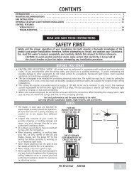
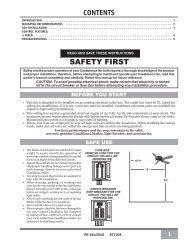
DUAL W-74 INSTALLATIONTo control the fan <strong>and</strong> lights from two locations (a three-waycircuit), use two W-74 wall controls as shown in the wiring diagramin Figure #4. Before installing the two switches into the wall, placeboth switches side by side, then locate the 6 dip switches on theside of the two switches as shown in Figure #3. Then make sure thatthe dip switches are set to the same address on both switches asshown in Figure #3. When setting these dip switches you are settingthe channel number that is required to control both your fan <strong>and</strong>lights from both sides of the room. If you are installing other Direct-Touch TM 3 fans within your home you may need to reset the dipswitches on these other fans to a different channel before installingyour W-74 wall control into the wall. Please review the section onchannel changing within this part of the operation manual as shownon page #20.DIP SWITCHES120V ACBLACKCAUTION!Figure 3Ensure power is turned OFF at the breaker or fuse panel before starting installation.NEBLACK WITHWHITE STRIPEWHITEGREENW-74TRALGREENBLACKBLACKREDREDREDBLACKGREENREDBLACKBLACK WITHWHITE STRIPEW-74Figure 46. Remove the two remaining wires from the three-wayswitch. Connect the black wire of these wires to a blackwire on the W-74 control. Secure the splice with a wire nut.The remaining red wire is to be connected to the other redwire on theW-74. Secure the splice with a wire nut. Figure 57. Connect the green ground wire coming from the back of theW-74 control to the ground wire in the switch box. Securethe splice with a wire nut.8. Check your work by using the wiring diagrams as shown inFigures # 4 <strong>and</strong> #5 on this page.9. Install the W-74 in the wall box with the two long screwsprovided.10. Install the wall plate with the two short color-matchedscrews provided.11. Installation of the second W-74 control is identical. Repeatsteps 1 through 7.BLACKBLACKBLACK1. To control the fan <strong>and</strong> lights from twolocations (a three-way circuit), use two W-74wall controls.2. Remove the screws <strong>and</strong> switch plate from theexisting switch box <strong>and</strong> the screws holdingthe switch in the switch box. Figure #53. Pull the existing switch from the switch box toexpose the wire connections.4. Determine which wire is connected to thecommon terminal from the power source(120V AC) of the three-way switch. (Theterminal will be marked on switch).5. Remove the wire from the common terminalof the three-way switch. Connect this wire tothe remaining black/white striped wire on theW-74 control. Secure this splice with a wirenut. Figure 42 BLACKWIRESFigure 5W-74Wall Control2 RED WIRESBLACK AND WHITESTRIPED WIRE18