TERCERA ⢠Owner's Manual - Del Mar Fans and Lighting
TERCERA ⢠Owner's Manual - Del Mar Fans and Lighting
TERCERA ⢠Owner's Manual - Del Mar Fans and Lighting
- No tags were found...

Create successful ePaper yourself
Turn your PDF publications into a flip-book with our unique Google optimized e-Paper software.
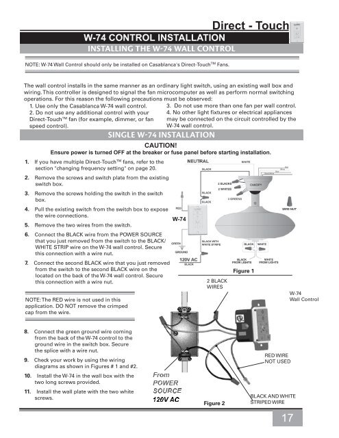
W-74 CONTROL INSTALLATIONINSTALLING THE W-74 WALL CONTROLNOTE: W-74 Wall Control should only be installed on Casablanca's Direct-Touch TM <strong>Fans</strong>.Direct - TouchThe wall control installs in the same manner as an ordinary light switch, using an existing wall box <strong>and</strong>wiring. This controller is designed to signal the fan microcomputer as well as perform normal switchingoperations. For this reason the following precautions must be observed:1. Use only the Casablanca W-74 wall control.2. Do not use any additional control with yourDirect-Touch TM fan (for example, dimmer, or fanspeed control).SINGLE W-74 INSTALLATION3. Do not use more than one fan per wall control.4. No other light fixtures or electrical appliancesmay be connected on the circuit controlled by theW-74 wall control.CAUTION!Ensure power is turned OFF at the breaker or fuse panel before starting installation.1. If you have multiple Direct-Touch TM fans, refer to thesection "changing frequency setting" on page 20.2. Remove the screws <strong>and</strong> switch plate from the existingswitch box.3. Remove the screws holding the switch in the switchbox.4. Pull the existing switch from the switch box to exposethe wire connections.5. Remove the two wires from the switch.6. Connect the BLACK wire from the POWER SOURCEthat you just removed from the switch to the BLACK/WHITE STRIP wire on the W-74 wall control. Securethis connection with a wire nut.7. Connect the second BLACK wire that you just removedfrom the switch to the second BLACK wire on thelocated on the back of the W-74 wall control. Securethis connection with a wire nut.NOTE: The RED wire is not used in thisapplication. DO NOT remove the crimpedcap from the wire.W-742 BLACKWIRESFigure 1Black/WhiteBlueRedWhiteW-74Wall Control8. Connect the green ground wire comingfrom the back of the W-74 control to theground wire in the switch box. Securethe splice with a wire nut.9. Check your work by using the wiringdiagrams as shown in Figures # 1 <strong>and</strong> #2.10. Install the W-74 in the wall box with thetwo long screws provided.11. Install the wall plate with the two whitescrews.Figure 2RED WIRENOT USEDBLACK AND WHITESTRIPED WIRE17