TERCERA ⢠Owner's Manual - Del Mar Fans and Lighting
TERCERA ⢠Owner's Manual - Del Mar Fans and Lighting
TERCERA ⢠Owner's Manual - Del Mar Fans and Lighting
- No tags were found...

You also want an ePaper? Increase the reach of your titles
YUMPU automatically turns print PDFs into web optimized ePapers that Google loves.
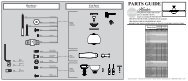
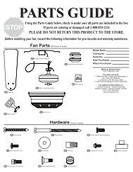
Parts ListParts List24252625512204221192123Item # # Item Name Name1 Hanging System25 Canopy23 Screw, 10-3224 Ceiling Plate26 Trim Ring20 Screw, Wood # 1021 Screw, Wood # 822 Washer4 Hanger Pipe5 Adapter Cover6 Blade Set8 Hardware Pack B7 Grommets24 Set Screw (pre-installed)9 Glass Assembly11 Screw Driver Phillips12 50W Halogen Bulb25 Balancing Kit10 Receiver17 Wire Nut (Small)17 Wire Nut (Large)11 Wall Control Assembly12 W74 Single Control13 Décor Wall Plate (White)14 Wire Nut15 Screw 6-32 X .7516 Screw 6-32If you are in need of service parts, do not return this fan to the store.
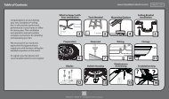
MOUNTING BRACKET INSTALLATION (CONT.)Step 1. Align the slotted holes in the ceiling platewith the pilot holes you drilled in the wood supportstructure. For proper alignment use slotted holesdirectly across from each other.JoistNote: The isolators should be flush against theceiling.Step 2. Place a flat washer on each of the two3” wood screws <strong>and</strong> pass the screws through theslotted holes in the ceiling plate into the pilot holesyou drilled.Step 3. Tighten the screws into the 9/64” pilotholes; do not use lubricants on the screws. Do notover tighten.Ceiling FanApprovedWiring BoxNote: On sloped ceilings, alignthe canopy opening towardthe top or peak of the room.WasherWoodScrewPREPARATION HARDWAREHanging AdapterCoverSET SCREW(pre-installed)Perma•Lock Downrod<strong>and</strong> Ball AssemblyCanopyFAN PREPARATIONTrim RingPrepare for fan installation as follows:Step 1. Remove the paper shield from the motoras shown in Figure #1.Step 2. Loosen the set screw making sure thatend of the Set Screw can not be seen within themotor coupling as shown in (Figure #2). If so, youwill need to unscrew the Set Screw so that the tipof the Set Screw does not remain in the path of thedownrod.PAPER MOTORSHIELDSet ScrewFIGURE 1.8CAUTION: Failure to fully lock in thedownrod before securely tightening theset screw may cause the fan to separatefrom the downrod <strong>and</strong> fall during normaloperation.FIGURE 2.
WIRING HARDWARETercera Receiver Blue Wire Caps (3) Orange Wire Caps (3)Step 1. Locate the White Line Neutral (IN) <strong>and</strong>connect it to the White Neutral Wire from yourceiling using one of the supplied orange wire caps.Step 2. Connect the Black Line Power (IN) <strong>and</strong> theBlack Power Wire from your ceiling with an orangewire cap.WIRINGPower FromCeilingLine Power(IN)Line Neutral(IN)WhiteNeutral FromCeilingStep 3. Tuck the White <strong>and</strong> Black connected wiresback into the ceiling box through the hole in thecenter of the Hanger Bracket while you slide theReceiver into the open end of the Hanger Bracket asshown.NOTE: Ensure you do not tuck the bare groundwire from the ceiling back into the box. This will beconnected later.Bare GroundWireTuck Wiresin BoxStep 4. Connect the Blue Downlight Power Wirefrom the Receiver to the Blue Wire coming from thefan with a blue wire cap.Step 5. Take the White Neutral to Fan Wire <strong>and</strong>connect it to the White Wire coming from the fanwith a blue wire cap.Blue -DownlightPower11
CANOPY HARDWARETercera Canopy Screw (4)SECURING THE CANOPYScrew DriverCanopy ScrewsStep 1. Carefully tuck the wires around theReceiver <strong>and</strong> Hanging Bracket as not to loosen thewire caps.Step 2. Insert 2 Canopy Screws into the HangingPlate diagonally across from each other so theymatch the keyholes on the canopy.WARNING: Do not let wiresbecome lodged betweenHanger Bracket <strong>and</strong> Canopy.Keyhole SlotsStep 3. Raise the Canopy over the Hanger Bracket.Align the partially installed screws with the key slotsin the canopy.Step 4. Twist the Canopy clockwise to secure.Step 5. Install the third & fourth canopy screws inthe round holes on Canopy. Securely tighten all fourscrews.Step 6. Using both h<strong>and</strong>s, push the Canopy Trimring up to the top of the Canopy.Step 7. Twist the Canopy Trim ring clockwise tosecure it to the Canopy.RoundHoleKeyhole Slot13
BLADE HARDWAREScrew DriverBlades (3) Grommets (9) Blade Screws (9)Blade Washers (9)Step 1. Locate the blade slot on the side of the fanas shown in Figure 1., <strong>and</strong> insert the blade into theslot.BLADE INSTALLATIONBlade SlotBladeStep 2. Align the holes in the blade with the holeson the fan as shown in Figure 2.FIGURE 1.Step 3. Insert the Blade Screws into the Washersthen Grommets.Step 4. Insert the Blade Screw, Washer, <strong>and</strong>Grommet through the blade <strong>and</strong> screw into thefan using either the provided Screw Driver or ast<strong>and</strong>ard Phillips head. Once all 3 Screws <strong>and</strong>Grommets have been installed, tighten securely.CAUTION:Blade screws must be tightened securelybefore operating the fan.Step 5. Repeat steps 3 <strong>and</strong> 4 for the remaining twoblades.14FIGURE 2.FIGURE 3.
LIGHT HARDWARETercera E11 50W Halogen BulbLIGHT INSTALLATIONGlass AssemblyStep 1. Install both Halogen Bulbs into the LightKit. Figure 1.Note: When replacing bulbs, only replace with max50 watt bulbs.IMPORTANT ! When installing the halogen bulb,carefully cut off the end of the plastic sleeve thebulb comes in <strong>and</strong> hold the bulb by the plasticsleeve to screw it into the socket.FIGURE 1.Step 2. Position the indentations in the outer rim ofthe glass shade so that they line up with the tabs onthe inside surface of the fan light fixture rim.Step 3. Carefully lift the glass shade up inside thelight fixture as far as it will go. Figure 2.FIGURE 2.Step 4. Rotate the shade in a clockwise directionuntil it is held tightly in place by the four tabs. Figure3.FIGURE 3.15
W-74 WALL CONTROL PREPARATIONWARNING!To avoid possible electrical shock, makecertain that electricity is turned off at thecircuit breaker or fuse box before attemptingany installation or repair procedureFuse Box(Remove fuse for thecircuit you will beworking on)Circuit Breaker(Trip breaker for thecircuit you will beworking on)CAUTION! NOT turning the power OFF at thecircuit breaker or fuse box may cause damageto the electronics within the wall control <strong>and</strong> orthe PC board on the fan.16
W-74 CONTROL INSTALLATIONINSTALLING THE W-74 WALL CONTROLNOTE: W-74 Wall Control should only be installed on Casablanca's Direct-Touch TM <strong>Fans</strong>.Direct - TouchThe wall control installs in the same manner as an ordinary light switch, using an existing wall box <strong>and</strong>wiring. This controller is designed to signal the fan microcomputer as well as perform normal switchingoperations. For this reason the following precautions must be observed:1. Use only the Casablanca W-74 wall control.2. Do not use any additional control with yourDirect-Touch TM fan (for example, dimmer, or fanspeed control).SINGLE W-74 INSTALLATION3. Do not use more than one fan per wall control.4. No other light fixtures or electrical appliancesmay be connected on the circuit controlled by theW-74 wall control.CAUTION!Ensure power is turned OFF at the breaker or fuse panel before starting installation.1. If you have multiple Direct-Touch TM fans, refer to thesection "changing frequency setting" on page 20.2. Remove the screws <strong>and</strong> switch plate from the existingswitch box.3. Remove the screws holding the switch in the switchbox.4. Pull the existing switch from the switch box to exposethe wire connections.5. Remove the two wires from the switch.6. Connect the BLACK wire from the POWER SOURCEthat you just removed from the switch to the BLACK/WHITE STRIP wire on the W-74 wall control. Securethis connection with a wire nut.7. Connect the second BLACK wire that you just removedfrom the switch to the second BLACK wire on thelocated on the back of the W-74 wall control. Securethis connection with a wire nut.NOTE: The RED wire is not used in thisapplication. DO NOT remove the crimpedcap from the wire.W-742 BLACKWIRESFigure 1Black/WhiteBlueRedWhiteW-74Wall Control8. Connect the green ground wire comingfrom the back of the W-74 control to theground wire in the switch box. Securethe splice with a wire nut.9. Check your work by using the wiringdiagrams as shown in Figures # 1 <strong>and</strong> #2.10. Install the W-74 in the wall box with thetwo long screws provided.11. Install the wall plate with the two whitescrews.Figure 2RED WIRENOT USEDBLACK AND WHITESTRIPED WIRE17
DUAL W-74 INSTALLATIONTo control the fan <strong>and</strong> lights from two locations (a three-waycircuit), use two W-74 wall controls as shown in the wiring diagramin Figure #4. Before installing the two switches into the wall, placeboth switches side by side, then locate the 6 dip switches on theside of the two switches as shown in Figure #3. Then make sure thatthe dip switches are set to the same address on both switches asshown in Figure #3. When setting these dip switches you are settingthe channel number that is required to control both your fan <strong>and</strong>lights from both sides of the room. If you are installing other Direct-Touch TM 3 fans within your home you may need to reset the dipswitches on these other fans to a different channel before installingyour W-74 wall control into the wall. Please review the section onchannel changing within this part of the operation manual as shownon page #20.DIP SWITCHES120V ACBLACKCAUTION!Figure 3Ensure power is turned OFF at the breaker or fuse panel before starting installation.NEBLACK WITHWHITE STRIPEWHITEGREENW-74TRALGREENBLACKBLACKREDREDREDBLACKGREENREDBLACKBLACK WITHWHITE STRIPEW-74Figure 46. Remove the two remaining wires from the three-wayswitch. Connect the black wire of these wires to a blackwire on the W-74 control. Secure the splice with a wire nut.The remaining red wire is to be connected to the other redwire on theW-74. Secure the splice with a wire nut. Figure 57. Connect the green ground wire coming from the back of theW-74 control to the ground wire in the switch box. Securethe splice with a wire nut.8. Check your work by using the wiring diagrams as shown inFigures # 4 <strong>and</strong> #5 on this page.9. Install the W-74 in the wall box with the two long screwsprovided.10. Install the wall plate with the two short color-matchedscrews provided.11. Installation of the second W-74 control is identical. Repeatsteps 1 through 7.BLACKBLACKBLACK1. To control the fan <strong>and</strong> lights from twolocations (a three-way circuit), use two W-74wall controls.2. Remove the screws <strong>and</strong> switch plate from theexisting switch box <strong>and</strong> the screws holdingthe switch in the switch box. Figure #53. Pull the existing switch from the switch box toexpose the wire connections.4. Determine which wire is connected to thecommon terminal from the power source(120V AC) of the three-way switch. (Theterminal will be marked on switch).5. Remove the wire from the common terminalof the three-way switch. Connect this wire tothe remaining black/white striped wire on theW-74 control. Secure this splice with a wirenut. Figure 42 BLACKWIRESFigure 5W-74Wall Control2 RED WIRESBLACK AND WHITESTRIPED WIRE18
1 204 31 2W-74 OPERATIONOPERATION POWERThe 0 power button is normally left in the on position. Always turn the4 power 3off during cleaning or servicing the fan <strong>and</strong> during thunderstorms. Itis also used to exit or enter additional programs.The power button must be left on to retain a previously set fan speedor light level.OPERATION SPEED CONTROLThere are five individual speed settings for the fan. Each speed isindicated by the number on the controller <strong>and</strong> an audible tone foreach speed.To select the desired fan speed:Press the number on the controller corresponding to the speeddesired. 4 is high, 3 medium, 2 low, 1 ultra-low, <strong>and</strong> 0 is off.Direct - Touch1 204 31 204 3Note: It is normal for the fanto start in the "High" positionfrom "Off" before changing tothe selected speed.OPERATION REVERSING AIRFLOWThe direction of airflow can be changed from downward to upwardor from upward 1 to downward. 20To reverse the airflow:4 31. Make sure the fan is on <strong>and</strong> blades are turning.2. Press the reverse button. You will hear a series of clicksfrom the fan as it speeds up before coming to a stop <strong>and</strong>changing direction.OPERATION LIGHTS1 204 3To turn the lights off <strong>and</strong> on, press <strong>and</strong> release the button forless than one second.1 20To dim the light, Press <strong>and</strong> hold the button for more than 1second. The light will come on at the last brightness 4 setting 3 <strong>and</strong>increase in brightness until full power 1 is reached, 2 then start dimminguntil the lowest setting is reached. This 0 cycle will repeat until yourelease the light button.4 3Down LightNote: The dimming featurewill only work as long as thedimming feature remainsactive. See "Operation CFLmode".19
OPERATION CFL MODEYour fan has the ability to disable 1 the 2dimming feature to allow the use ofCFL bulbs.0To activate CFL mode:4 31. Turn the fan off by pressing thepower button.2. Allow the fan to remain off for at least 5 seconds.3. Press the power button again to restore power to the fan.4. Immediately press <strong>and</strong> hold 1 the "1" 2 <strong>and</strong> "3" buttons for at least 5 seconds. The fans lights will go to100% brightness <strong>and</strong> the dimming 0 function will be disabled.To cancel CFL mode:4 35. Turn the fan off by pressing thepower button.6. Allow the fan to remain off for at least 5 seconds.7. Press the power button again to restore power to the fan.CHANGING FREQUENCY SETTINGCaution: CFL bulbs will notfunction properly whendimmed, which may resultin flickering or reduced bulblife.8. Immediately press <strong>and</strong> hold the "2" <strong>and</strong> "4" buttons for at least 5 seconds. The fans lights will dim to50% brightness <strong>and</strong> the dimming function will be enabled. Press <strong>and</strong> hold the light buttons until thedesired dimmer setting is reached.NOTE: All fans leave the factory set to“111111”DIPSWITCHESYou will only have to change the dip switch settings in the remote if youare using more than one fan in the same area <strong>and</strong> want to control themseparately.NOTE: DO NOT set dip switch setting in theremote to ‘0000’, this may cause frequencyinterference from other Casablanca Products.DIP SWITCHESSET TO ‘111111’(Factory Setting)(Figure 1)1. Turn power OFF at the circuit breaker or fuse box <strong>and</strong> at the toggleswitch, for the fan you want to change.2. Remove the screws <strong>and</strong> switch plate from the existing switch box.3. Remove the screws holding the switch in the switch box.4. Pull the existing W-74 switch from the switch box to expose the dipswitches located on the side of the control as shown in Figure #1.5. Change the dip switch settings, assuring that they are different fromthe previously installed Direct-Touch fan.6. Mount the W-74 Wall Control unit back into the wall 1 electrical 2 box.7. At the circuit breaker or fuse box <strong>and</strong> at the toggle switch, 0 turn thepower off for the fan whose frequency you are 4changing.38. Within 20 seconds of restoring power to the ceiling fan <strong>and</strong> the W-74Wall Control press <strong>and</strong> hold both the “1” <strong>and</strong> reverse buttonsas shown in Figure #2. For 3 seconds, you will hear one tone fromthe Piezo Buzzer indicating the comm<strong>and</strong> has been accepted. The Fan<strong>and</strong> Lights will be off.20DIP SWITCHESSET TO ‘000000’(Figure 2)
Direct - TouchAUTOMATIC DEMONSTRATION PROGRAMProgrammed into every Direct-Touch fan is an Automatic DemonstrationProgram. 1 It can 2 be used to fully demonstrate <strong>and</strong> test the operation of thefan. 041 32To enter the demonstration program:01. Turn the power button off for at least 5 seconds. This will clear4 3the fan memory ready for programming.2. Turn thepower button on.3. Immediately hold the "0" button for at least 5 seconds.A multi-tone signal will verify the start of the test program. The fan <strong>and</strong>1 2lights will go through a series of changing fan speeds, reversing the fanoperation mode, 0 turning off/on, <strong>and</strong> dimming the lights.4 3The complete cycle lasts slightly over one minute. It will continue torepeat until the is turned off for more than five seconds, cancellingthe program.1 2OPERATION SAFE-EXIT®The Safe-Exit 0 Program gives you about thirty seconds of light when you turn thelights off, 4 enabling 3 you to exit your home before the lights go out. To enter the Safe-Exit Program:1. Press the power button off for at least five seconds.Safe-Exit2. Turn the Power on. Immediately press <strong>and</strong> hold the "4" button for 5 seconds.When a light button is pressed, an audio tone <strong>and</strong> series of lights blinking will indicate the program1 2is active. When CFL mode is disabled, the Lights will stay on at 50% brightness for 20 seconds thendecrease in intensity for 30 seconds then 0turn off.4 33. With CFL mode active, the lights will turn off after 30 seconds.4. To cancel the Safe-Exit Program, press the1 2The Light-Minder Program automatically turns OFF the fan mounted 0 lights after twohours. To 1 enter 2the Light-Minder Program:4 301. To operate the lights for Light Minder Program – Turn the4 3for at least 5 seconds.power button off2. Turn the on. Immediately press <strong>and</strong> hold the "1" button for 5 seconds. Aseries of tones will be heard through the piezo-buzzer indicating the comm<strong>and</strong>has been accepted. Once the lights turn on, they will automatically turn off after2 hours.Light-Minder3. Light operation still remains normal, if you 1 leave 2the room <strong>and</strong> turn OFF thelights, the lights will blink to indicate the Light 0 Minder comm<strong>and</strong> has beenaccepted. The lights will stay on for 2 hours <strong>and</strong> then begin to dim. After thirty seconds have elapsed,4 3the lights will turn completely off. In CFL Mode, the lights will not dim, but shut off after 2 hours.4. To cancel the Light Minder Program, press thepower button <strong>and</strong> leave off for five seconds.LIGHT-MINDER® PROGRAMNote: With CFL mode active,the lights will not dim.power button <strong>and</strong> leave off for five seconds.21
1 21 201. To operate the Home-Safe Program – Turn the4 3least 5 seconds.0OPERATION 4 HOME-SAFE® 3PROGRAMpower button off for at2. Turn the on. Immediately press <strong>and</strong> hold the "3" button for 5 seconds.A series of tones will be heard through the piezo-buzzer indicating thecomm<strong>and</strong> has been accepted.Note: This program overrides all manual control of lights <strong>and</strong> fan.3. The lights will automatically cycled on <strong>and</strong> 1 off in 2a controlled sequence asfollows: ON 1 hour, OFF ½ hour, ON 2 hours, 0OFF 1 hour, ON ½ hour thenOFF 2 hours. This seven hour pattern will repeat continuously so that a4 3different pattern of lighting is seen each day of the week.4. 4) To cancel the Home-Safe Program, press theseconds.Button OFF for fiveOPERATION FAN-MINDER PROGRAM1 2The Fan-Minder feature will add to your comfort when used in 0the bedroom. The programreduces 1the speed 2 of the fan each two-hour interval to compensate 4 3 for cooling night air.01. To operate the lights for Light Minder Program – Turn the4 3at least 5 seconds.power button off for2. Turn the on. Immediately press <strong>and</strong> hold the "2" button for 5 seconds. Aseries of tones will be heard through the piezo-buzzer indicating the comm<strong>and</strong>has been accepted. Once the lights turn on, they will automatically turn off after 2hours.3. The fan will respond with three descending tones. A timer is now initiated <strong>and</strong> the fanwill reduce one speed for each two-hour1interval.2The fan will not, however, descendbelow the first or the lowest speed.04. You may increase the fan speed by pressing <strong>and</strong> holding any of the fan speed buttons until the desired4 3speed is reached, then release it. The fan will again reduce one speed for each 2 hour interval.5. To cancel the Fan-Minder Program, turn theOFF for 5 seconds.22
Tercera TROUBLESHOOTING TIPSPlease refer to this troubleshooting guide before requesting service or contacting your dealer for assistance.PROBLEMPOSSIBLE REMEDIESFan will not start• Check the main circuit fuses, circuit breakers, <strong>and</strong> wall switch position. Check all wire connections.Make sure the power 1 is turned 2 off during this inspection.• Pin connectors are not making good contact. Check all connections.0• The fan receiver is defective. Replace the fan receiver.• Reset the frequency 4 setting: 3 Turn the power off at the circuit breaker for the fan that is not functioningonly. Within 20 seconds from restoring power to the ceiling fan <strong>and</strong> the W-74 Wall Control press <strong>and</strong> holdboth the “1” <strong>and</strong> reverse buttons as shown in Figure #2 for 3 seconds, you will hear one tone fromthe Piezo Buzzer indicating the comm<strong>and</strong> has been accepted. The Fan will come on at “low” speed in thereverse direction.Fan wobbles or shakes excessively• Be sure the canopy pin is set properly into the slot on the ball.• Check that the blade holders have not been bent during installation <strong>and</strong> the blades are balanced.• The hanger bracket <strong>and</strong>/or the ceiling outlet are attached too loosely. Make sure the hanger bracket isattached tightly to the ceiling outlet box <strong>and</strong> the downrod assembly is secured firmly.• The downrod is attached to the downrod base too loosely. Make sure all the screws are securelytightened.• A balancing kit is supplied with the fan to remedy slight wobble problems. Check all previous stepsbefore using this kit.Fan is noisy during operation• When changing fan speeds or reversing the fan, you may hear several audible clicks. This is normaloperation.• Check <strong>and</strong> tighten the light fixture retaining screws, glass shade screws, <strong>and</strong>/or lightbulb(s).• Tighten the canopy screws <strong>and</strong> mounting plate assembly. Make sure the wire nuts inside the canopy<strong>and</strong> switch housing are not touching the metal parts <strong>and</strong> that they have not fallen off the wire splices.Tighten as necessary.• Tighten the blade holders to the flywheel (or Direct Drive motor) <strong>and</strong> the blades to the bladeholderscrews.• Make sure all the screws in the motor housing are snug but not overly tight.Fan does not run on low speed• If fan is new, it may need to be “broken in.” Run at high speed for several days.Light is too dim• Make sure the dimmer setting is at the desired level.Hold the light button to activate the dimmer ofthe light. Release the button when the desired luminosity is reached.This device complies with RSS-210 of Industry Canada. Operation is subject to the following two conditions: (1) this1 2device may not cause interference, <strong>and</strong> (2) this device must accept any interference, including interference that maycause undesired operation of the device.01. This device complies with part 15 of the FCC Rules. Operation is subject 4 3to the following two conditions: (1) thisdevice may not cause harmful interference, <strong>and</strong> (2) this device must accept any interference received, includinginterference that may cause undesired operation.2. This equipment has been tested <strong>and</strong> found to comply with the limits for a Class B digital device, pursuant to Part15 of the FCC Rules. These limits are designed to provide reasonable protection against harmful interference in aresidential installation. This equipment generates, uses <strong>and</strong> can radiate radio frequency energy <strong>and</strong>, if not installed<strong>and</strong> used in accordance with the instructions, may cause harmful interference to radio communications. Howeverthere is no guarantee that interference will not occur in a particular installation. If this equipment does causeharmful interference to radio or television reception, which can be determined by turning the equipment off <strong>and</strong>on, the user is encouraged to try to correct the interference by one or more of the following measures: Reorientor relocate the receiving antenna, Increase the separation between the equipment <strong>and</strong> receiver, Connect theequipment into an outlet on a circuit different from that to which the receiver is connected. Consult the dealer oran experienced radio/TV technician for help. Note: Any changes or modifications to the transmitter or receiver notexpressly approved by Casablanca Fan Company may void one’s authority to operate this remote control.23
Fan Finishes• For cleaning, a soft brush or lint-free cloth should be used to prevent scratching the finish.• A vacuum cleaner brush nozzle can remove heavier dust.• Surface smudges or an accumulation of dirt <strong>and</strong> dust can be removed easily using a mild detergent<strong>and</strong> slightly dampened soft cloth. An antistatic agent may be used, but never use abrasive cleaningagents as these will damage the finish.Blades• Wood-finish blades should be cleaned with a furniture polishing cloth. Occasionally, a light coat offurniture polish may be applied for added protection <strong>and</strong> beauty.• For painted <strong>and</strong> high-gloss blades, surface smudges or an accumulation of dirt <strong>and</strong> dust can beremoved easily using a mild detergent <strong>and</strong> slightly dampened soft cloth. An antistatic agent may beused, but never use abrasive cleaning agents as these will damage the finish.No Need for Lubrication• Never lubricate this fan! The precision motor at the heart of your Casablanca fan features sealedbearings that are lubricated for life.• Do not attempt to oil the motor.Changing LightbulbsCARE RECOMMENDATIONS• Be sure to turn the power to OFF at the wall switch or circuit breaker before changing lightbulbs.• Replace bulbs with the same type as you removed from the light fixture.• The maximum wattage rating for this fan’s light kit is 100 watts.FOR QUESTIONS OR TO LOCATE THE NEAREST CASABLANCAAUTHORIZED SERVICE CENTERCALL TOLL FREE: 1-888-227-2178OR VISIT US ON THE WEB AT: WWW.CASABLANCAFANCO.COMPRODUCT SPECIFICATIONSModel Name: TerceraModel Number: C22GxxLDimensions: A = 11.9B = 14.4C = 3.4D = 12.9E = 7.6Weight:27 lbs.Motor: 172mm x 20mm Direct DriveBlade Span With: 52"Blade Pitch: 15°No. of Blades: 3Technology: W-74SL- Direct-TouchLightbulbs: 50-watt Halogen (2)Airflow: 5,577 cfmElectricity Use: 64 wattsAirflow Efficiency: 87.7 cfm/watt24