DC motors - Valtek
DC motors - Valtek
DC motors - Valtek
- No tags were found...

You also want an ePaper? Increase the reach of your titles
YUMPU automatically turns print PDFs into web optimized ePapers that Google loves.
G-motion<strong>DC</strong> <strong>motors</strong>
No matter which drive solution youimagine, we make your dreams come true.True to our slogan (one stop shopping)we offer you a complete programme ofelectronic and mechanical drive systemswhich is distinguished by reliability andefficiency.The scope of our programme includesfrequency inverters, servo controllers,variable-speed drives, speed reductiongearboxes, <strong>motors</strong>, brakes, clutches,decentralised I/O and operator and displayunits.Many well-known companies use Lenze productsin various applications.
Product keyfor electrical machinesProduct groupM MotorCurrentD = Three-phase currentE = AC single phase currentG = <strong>DC</strong> currentU = Universal motorCooling/ventilationF = External ventilationE = Self-ventilation (speed-dependent)S = Natural ventilation (no ventilation)Design/enclosureG = Smooth, round enclosureQ = Smooth, square enclosureR = Ribbed, round enclosureV = Ribbed, square (oval) enclosureE = Explosion-proofMachine typeU = UncompensatedK = CompensatedE = Increased safety (Ex) eP = Permanent magnet motorA = AsynchronousS = SynchronousD = Explosion-proof (Ex) dF = Explosion-proof (Ex) pMountingsTA = Tacho, analog signal sourceBR = BrakeRS = ResolverIG = Incremental encoder (pulse encoder)AG = Absolute value encoderBS = Brake + resolverBT = Brake + tachoBA = Brake + absolute value encoderBI = Brake + incremental encoderBU = Brake, tacho and pulse encoderTI = Tacho and pulse encoderXX = no mountingsSizeShaft height in mountingsB 3 032 – 400 according to LHM 7.00 01 03Length according to LHM 7.00 00 150 = VS very short1 = S short2 = M middle3 = L long4 = VL very longX X X X X X X X X X X XPole pairs1 = p = 1 (2p = 2- 2-pole)2 = p = 2 (2p = 4- 4-pole)3 = p = 3 (2p = 6- 6-pole)9 = p = 9 (2p = 18- 18-pole)
<strong>DC</strong> <strong>motors</strong> compact with high power reservesLenze <strong>DC</strong> <strong>motors</strong> characteristically offer highperformance together with exceptionally smoothrunning characteristics across a wide speed andtorque setting range. They can be controlled withexceptional accuracy using our cost-effective <strong>DC</strong>speed controllers, and achieve speed control ranges> 1:1000 even in reversing duty – as well as withhigh starting currents – when used for example as awinder.Reliable low-noise cooling systems andcorrespondingly designed commutation systemsoffer the ideal basis for the high power reserveswhich are required, for example, in dynamicpositioning applications. The <strong>DC</strong> <strong>motors</strong> in the powerband up to 90 kW and above are available as amodular system with various enclosures. Dependingon the application, these <strong>motors</strong> can be combinedwith the optimumgearboxes, brakes or feedback systems. The designof the <strong>motors</strong> ensures long service life with minimalmaintenance requirements and therefore representsan efficient and cost-effective choice of drive.
LenzeAn introductionLenze is the competent partner for yourapplication. Lenze is not only a supplier forsingle components but also offers solutionsfor complete drive systems includingplanning, execution and commissioning.Furthermore, a worldwide service anddistribution network lets you engage aqualified customer advisory service and anafter sales service that is fast and extensive.Our quality assurance system for design,production, sales and service is certifiedaccording to DIN ISO 9001 : 2000. Ourenvironmental management system isalso certified to DIN EN ISO 14001.Our customers set the standards formeasuring the quality of our products.Our task is to meet your requirements, sincecustomer orientation is a Lenze principledemanding the best quality.See for yourself.A worldwide service –Our team of experts provides reliable andprofessional assistance.
Contents<strong>DC</strong> <strong>motors</strong>Motor featuresMGFRK/MGFQU/MGFQK series 8<strong>DC</strong> <strong>motors</strong> IP54, IP55Technical Information MGFRK series 11Technical data MGFRK series 12Dimensions MGFRK series 17<strong>DC</strong> <strong>motors</strong> IP23s, IP43s, IPR44Technical Information MGFQU/MGFQK series 21Technical data MGFQU series 22Technical data MGFQK series 28Dimensions MGFQU/MGFQK series 32Lenze worldwide36<strong>DC</strong> <strong>motors</strong> en 12/20047
<strong>DC</strong> <strong>motors</strong>Motor featuresMGFRK/MGFQU/MGFQK seriesInsulation and impregnationAll <strong>motors</strong> are of temperature class F (permissiblepermanent temperature 155 °C) and are provided with aspecial impregnation of the windings.Temperature monitoringA normally closed bimetal switch that reacts at 155 °C isfitted as standard to all <strong>motors</strong> of the MGFRK, MGFQU andMGFQK series. Thermistors may also be fitted. This does,however, not ensure thermistor-type motor protection. Airflow monitors may be fitted to external radial blowers ofthe MGFQU and MGFQK series.Fitting brakes and actual value encodersOn request, we can fit Lenze spring-operated brakes. As astandard we can also fit the following tachogenerators:˘ Three-phase AC hollow shaft tachogenerator TD3-30 V/1000 min-1;˘ <strong>DC</strong> hollow shaft tachogeneratorGT (GTF) 7.08 L/420 - 20 V/1000 min-1;˘ Resolver˘ Hollow shaft pulse encoder ITD 21Ambient temperature TK and the influence on the ratedpowerWithout special measures, temperatures between -20 °Cand +40 °C are permissible.T K (°C) 30 40 45 50 55 60P/P N (%) 117 100 95 90 83 77for MGFQK 160 / MGFQU 160T K (°C) 25 40 45 50 55 60P/P N (%) 100 83 78 74 68 64Influence of the altitude h on the rated powerh (amsl) 1000 2000 3000 4000 5000P/P N (%) 100 92 83 77 67Rated powersThe rated powers shown in the table are based on a formfactor FF = 1.05.For higher form factors, the output must be reduced.If a standard separately driven fan is fitted, a constanttorque may be obtained to almost standstill. The maximumpermissible load period under rated current duringstandstill is 30 s for the MGFRK series and 10 s for theMGFQU/MGFQK series.8 <strong>DC</strong> <strong>motors</strong> en 12/2004
<strong>DC</strong> <strong>motors</strong>Motor featuresMGFRK/MGFQU/MGFQK seriesField weakeningA field weakening range of 1:3 for MGFRK and MGFQK<strong>motors</strong>, and of 1:1.2–1:1.5 for MGFQU <strong>motors</strong> is generallypossible with constant power. For mechanical reasons,however, the overspeed test speed must not be exceeded.Special designs for higher speeds and field weakening rangescan be provided.Radio interference suppressionRadio interference suppression of the machine is almostensured due to the symmetrically arranged auxiliarycommutator windings and the spark-free commutation.Special measures can be taken to meet higher requirements.BalancingBalancing is done by half keys to DIN/ISO 8821 to vibrationlevel “N“ according to VDE 0530 T14. Level “S“ is possible onrequest. The shaft end and the key correspond to DIN 748and IEC recommendation 72.Noise levelThe noise level L A , as per DIN 45635 rating curve A, is belowthe admissible noise level as per DIN 57530/VDE 0530.Overload capacityOver a range of up to 3 times the nominal current, the<strong>motors</strong> of the MGFRK and MGFQK series provided with acompensating winding keep to exact proportionalitybetween current and torque. In this range, overload isalways possible if the effective value of the overall currentis not exceeded. Motors of the MGFQU series can provide1.6 times the nominal torque for approx. 20 s. The currentthen increases to approximately 2x I N .Terminal box positionThe standard terminal box position is “right” for the MGFRKseries; “top” for the MGFQU and MGFQK series for the sizes063-32 to 132-32, and “right” for the sizes 160-22 whenviewed from the output shaft end.MountingsStandard for the MGFRK series are mountings IMB 3, IMB 5and IMB 14, for the MGFQU and MGFQK series mountingsIMB 35 or IMB 34 to DIN IEC 34 T7. Other mountings arepossible. The ball bearings are rated for at least 20,000operating hours under nominal load conditions. In the basicdesign, the <strong>motors</strong> are equipped with permanently greasedball bearings. For high radial shaft loads, cylindrical rollerbearings are provided on the output side.Pg screwingsMotor type Motor terminal box Fan terminal boxQuantity and dimension max. cable Ø [mm] Quantity and dimension max. cable Ø [mm]MGFRK 090-22MGFRK 100-22 2xM25 16MGFRK 112-22 1xM16 9MGFRK 132-22MGFRK 160-222xM40 / 2xM16 27 / 9MGFQK 063-32MGFRU 080-222xM25 16MGFQU 100-22MGFQK 100-32 1xM40 / 1xM20 / 1xM16 27 / 13 / 9 1xP g 9 8MGFQU 112-22MGFQU 132-22 1xM50 / 1xM20 / 1xM16 35 / 13 / 9MGFQU/MGFQK 160-22MGFQU/MGFQK 160-324xM40 / 2xM25 27 / 16 1xP g 16 15<strong>DC</strong> <strong>motors</strong> en 12/20049
10 <strong>DC</strong> <strong>motors</strong> en 12/2004
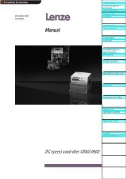
<strong>DC</strong> <strong>motors</strong>IP54, IP55MGFRK seriesTechnical informationThe <strong>DC</strong> <strong>motors</strong> of the MGFRK series represent the mostmodern motor construction, including: fully laminatedstators and rotors allowing high speeds of currentalternation with low losses and heat generation. Four-poledesign with skewed armatures and many commutatorsegments ensures high torque and smooth running, downto near standstill. Compensating windings ensure low fielddistortion and excellent spark-free commutation togetherwith the commutating poles. This is also true for highoverload current (3 x I N ) and bad form factors when usedwith <strong>DC</strong> controllers, which ensure long life of the brushes.Mechanically, the <strong>motors</strong> consist of components forstandard three-phase AC <strong>motors</strong>, enclosure IP 54.The mounting dimensions to IEC 72 as well as DIN 42673and DIN 42677 standards allow a direct connection withhelical, worm and helical worm gearboxes of the Lenzeproduct range and of other suppliers. The standard motortypes MGFRK 090-160 are of enclosure IP 54, they areaxially cooled temperature class F <strong>motors</strong> (enamelled wirequality corresponds to temperature class “H” whichincreases life) and have a normally closed thermal bimetalcontact. Due to our modular design, many options can beprovided. These comprise AC and <strong>DC</strong> tachogenerators,incremental encoders and brakes as well as combinationsof these.MGFRKBT 090-22 with brake and tachogenerator<strong>DC</strong> <strong>motors</strong> en 12/200411
<strong>DC</strong> <strong>motors</strong>IP44, IP54, IP55MGFRK 090-22Technical dataData refers to:– Form factor F F = 1.05– Enclosure IP 54– Cooling (forced ventilation) IC 0541– Continuous operation S1– Insulation class FTotal weightm = 21 kgInertia J = 0.004 kgm 2Field excitationU F = 210 V I F = 0.60 AU F = 360 V I F = 0.32 AA-side bearing6205-2RSR-C3B-side bearing6205-2RSR-C3Carbon brushes a) 6.3 x 12.5 x 20Permissible shaft load F r = 780 Nfor L/2 and n NF a = 440 N– reinforced bearing F rr = 2100 NFan variant220-240 V, 50-60 Hz, 0.22 A380-460 V, 50-60 Hz, 0.12 ACooling variant IC 0641/0741Cooling air volume 75 m 3 /hPressure drop36 PaP Speed n at voltage n F n Mech M I AN I Amax L A R a 125° Carbon brusheskW min -1 min -1 Nm A A mH Ω Quantity Variant170 V 280 V 420 V 460 V0.33 – 550 – – 1650 4500 5.5 2.3 7 156.2 54.38 4 a0.65 – – 1100 – 3300 4500 5.5 2.3 7 156.2 54.38 4 a0.7 – – – 1250 3750 4500 5.5 2.3 7 156.2 54.38 4 a0.2 350 – – – 1050 4500 5.6 3.0 9 99.5 34.95 4 a0.5 – 800 – – 2400 4500 5.6 3.0 9 99.5 34.95 4 a0.9 – – 1500 – 4500 4500 5.6 3.0 9 99.5 34.95 4 a1.0 – – – 1650 4500 4500 5.6 3.0 9 99.5 34.95 4 a0.27 480 – – – 1450 4500 5.7 3.5 10 70.5 23.35 4 a0.6 – 1100 – – 3300 4500 5.6 3.5 10 70.5 23.35 4 a1.1 – – 1900 – 4500 4500 5.5 3.5 10 70.5 23.35 4 a1.2 – – – 2100 4500 4500 5.5 3.5 10 70.5 23.35 4 a0.4 650 – – – 1950 4500 5.7 4.4 13 46.6 16.05 4 a0.85 – 1450 – – 4350 4500 5.7 4.4 13 46.6 16.05 4 a1.4 – – 2400 – 4500 4500 5.6 4.4 13 46.6 16.05 4 a1.6 – – – 2700 4500 4500 5.6 4.4 13 46.6 16.05 4 a0.5 870 – – – 2600 4500 5.9 5.3 16 33.2 11.52 4 a1.1 – 1800 – – 4500 4500 5.8 5.3 16 33.2 11.52 4 a1.8 – – 2950 – 4500 4500 5.7 5.3 16 33.2 11.52 4 a2.0 – – – 3300 4500 4500 5.7 5.3 16 33.2 11.52 4 a1.0 1650 – – – 4500 4500 5.8 8.3 25 14.1 4.53 4 a1.8 – 3050 – – 4500 4500 5.7 8.3 25 14.1 4.53 4 a1.9 3250 – – – 4500 4500 5.7 14.5 44 4.6 1.48 4 a12 <strong>DC</strong> <strong>motors</strong> en 12/2004
<strong>DC</strong> <strong>motors</strong>IP44, IP54, IP55MGFRK 100-22Technical dataData refers to:– Form factor F F = 1.05– Enclosure IP 54– Cooling (forced ventilation) IC 0541– Continuous operation S1– Insulation class FTotal weightm = 28 kgInertia J = 0.0061 kgm 2Field excitationU F = 210 V I F = 0.70 AU F = 360 V I F = 0.37 AA-side bearing6306-2RSR-C3B-side bearing6206-2RSR-C3Carbon brushes a) 8 x 12.5 x 20Permissible shaft load F r = 1000 Nfor L/2 and n NF a = 500 N– reinforced bearing F rr = 2700 NFan variant220-240 V, 50-60 Hz, 0.16 A380-460 V, 50-60 Hz, 0.06 ACooling variant IC 0641/0741Cooling air volume 105 m 3 /hPressure drop41.4 PaP Speed n at voltage n F n Mech M I AN I Amax L A R a 125° Carbon brusheskW min -1 min -1 Nm A A mH Ω Quantity Variant170 V 280 V 420 V 460 V0.5 – 530 – – 1600 4500 8.6 2.8 9 143.7 35.09 4 a0.85 – – 940 – 2800 4500 8.6 2.8 9 143.7 35.09 4 a0.95 – – – 1050 3150 4500 8.6 2.8 9 143.7 35.09 4 a0.35 350 – – – 1050 4500 8.7 3.7 12 80.8 19.6 4 a0.7 – 800 – – 2400 4500 8.5 3.7 12 80.8 19.6 4 a1.2 – – 1400 – 4050 4500 8.4 3.7 12 80.8 19.6 4 a1.35 – – – 1550 4500 4500 8.4 3.7 12 80.8 19.6 4 a0.55 600 – – – 1800 4500 8.5 5.0 15 43.8 10.7 4 a1.1 – 1200 – – 3600 4500 8.4 5.0 15 43.8 10.7 4 a1.7 – – 1900 – 4500 4500 8.2 5.0 15 43.8 10.7 4 a1.9 – – – 2150 4500 4500 8.2 5.0 15 43.8 10.7 4 a0.7 800 – – – 2400 4500 8.3 6.0 18 29.3 6.91 4 a1.3 – 1500 – – 4500 4500 8.2 6.0 18 29.3 6.91 4 a2.1 – – 2400 – 4500 4500 8.1 6.0 18 29.3 6.91 4 a2.3 – – – 2700 4500 4500 8.1 6.0 18 29.3 6.91 4 a0.85 900 – – – 2700 4500 8.6 7.0 21 22.6 5.7 4 a1.5 – 1700 – – 4500 4500 8.4 7.0 21 22.6 5.7 4 a2.4 – – 2750 – 4500 4500 8.3 7.0 21 22.6 5.7 4 a2.7 – – – 3100 4500 4500 8.3 7.0 21 22.6 5.7 4 a1.0 1100 – – – 3300 4500 8.4 7.9 24 17.7 4.25 4 a1.85 – 2100 – – 4500 4500 8.4 7.9 24 17.7 4.25 4 a2.9 – – 3300 – 4500 4500 8.3 7.9 24 17.7 4.25 4 a3.1 – – – 3600 4500 4500 8.3 7.9 24 17.7 4.25 4 a1.6 1800 – – – 4500 4500 8.9 12.3 36 7.7 1.84 4 a2.85 – 3200 – – 4500 4500 8.6 12.3 36 7.7 1.84 4 a2.7 3000 – – – 4500 4500 8.6 18.6 56 3.2 0.755 4 a<strong>DC</strong> <strong>motors</strong> en 12/200413
<strong>DC</strong> <strong>motors</strong>IP44, IP54, IP55MGFRK 112-22Technical dataData refers to:– Form factor F F = 1.05– Enclosure IP 54– Cooling (forced ventilation) IC 0541– Continuous operation S1– Insulation class FTotal weightm = 40 kgInertia J = 0.0142 kgm 2Field excitationU F = 210 V I F = 1.1 AU F = 360 V I F = 0.6 AA-side bearing6306-2RSR-C3B-side bearing6206-2RSR-C3Carbon brushes a) 8 x 12.5 x 20b) 8 x 10.0 x 20Permissible shaft load F r = 1500 Nfor L/2 and n NF a = 500 N– reinforced bearing F rr = 2800 NFan variant220-240 V, 50-60 Hz, 0.30 A380-460 V, 50-60 Hz, 0.15 ACooling variant IC 0641/0741Cooling air volume 150 m 3 /hPressure drop48 PaP Speed n at voltage n F n Mech M I AN I Amax L A R a 125° Carbon brusheskW min -1 min -1 Nm A A mH Ω Quantity Variant170 V 280 V 420 V 460 V1.1 – – 750 – 2250 4500 15.0 3.7 11 179.8 26.55 4 a1.3 – – – 850 2550 4500 15.0 3.7 11 179.8 26.55 4 a0.6 390 – – – 1200 4500 14.9 5.9 17 71.1 10.4 4 a1.2 – 800 – – 2400 4500 14.6 5.9 17 71.1 10.4 4 a2.0 – – 1300 – 3900 4500 14.5 5.9 17 71.1 10.4 4 a2.2 – – – 1450 4350 4500 14.5 5.9 17 71.1 10.4 4 a0.8 500 – – – 1500 4500 15.0 7.2 22 49.4 7.16 4 a1.6 – 1000 – – 3000 4500 14.9 7.2 22 49.4 7.16 4 a2.5 – – 1600 – 4500 4500 14.7 7.2 22 49.4 7.16 4 a2.8 – – – 1800 4500 4500 14.6 7.2 22 49.4 7.16 4 a1.1 700 – – – 2100 4500 15.1 9.0 27 31.6 4.72 4 a2.0 – 1300 – – 3900 4500 14.8 9.0 27 31.6 4.72 4 a3.2 – – 2050 – 4500 4500 14.7 9.0 27 31.6 4.72 4 a3.5 – – – 2300 4500 4500 14.6 9.0 27 31.6 4.72 4 a1.6 1000 – – – 3000 4500 15.5 12.4 38 17.8 2.55 4 a2.9 – 1850 – – 4500 4500 15.2 12.4 38 17.8 2.55 4 a4.5 – – 2850 – 4500 4500 15.0 12.4 38 17.8 2.55 4 a4.9 – – – 3200 4500 4500 14.9 12.4 38 17.8 2.55 4 a1.8 1150 – – – 3500 4500 15.0 13.6 41 14.2 2.0 4 a3.2 – 2050 – – 4500 4500 14.9 13.6 41 14.2 2.0 4 a5.0 – – 3200 – 4500 4500 14.7 13.6 41 14.2 2.0 4 a5.5 – – – 3550 4500 4500 14.6 13.6 41 14.2 2.0 4 a3.1 2000 – – – 4500 4500 14.8 22.0 66 5.5 0.55 8 b5.3 – 3450 – – 4500 4500 14.8 22.0 66 5.5 0.55 8 b14 <strong>DC</strong> <strong>motors</strong> en 12/2004
<strong>DC</strong> <strong>motors</strong>IP44, IP54, IP55MGFRK 132-22Technical dataData refers to:– Form factor F F = 1.05– Enclosure IP 54– Cooling (forced ventilation) IC 0541– Continuous operation S1– Insulation class FTotal weightm = 84 kgInertia J = 0.0411 kgm 2Field excitationU F = 210 V I F = 1.1 AU F = 360 V I F = 0.6 AA-side bearing6308-2RSR-C3B-side bearing6208-2RSR-C3Carbon brushes a) 10 x 16 x 20b) 10 x 12.5 x 20Permissible shaft load F r = 2200 Nfor L/2 and n NF a = 1100 N– reinforced bearing F rr = 4500 NFan variant220-240 V, 50-60 Hz, 0.55 A380-460 V, 50-60 Hz, 0.22 ACooling variant IC 0641/0741Cooling air volume 220 m 3 /hPressure drop63 PaP Speed n at voltage n F n Mech M I AN I Amax L A R a 125° Carbon brusheskW min -1 min -1 Nm A A mH Ω Quantity Variant280 V 420 V 460 V1.6 540 – – – 1600 4000 29.2 7.7 24 70.0 7.28 4 a2.7 – 880 – – 2650 4000 29.0 7.7 24 70.0 7.28 4 a3.0 – – 1000 – 3000 4000 29.0 7.7 24 70.0 7.28 4 a3.1 930 – – – 2800 4000 31.5 13.5 40 27.3 2.82 4 a4.9 – 1450 – – 4000 4000 31.3 13.5 40 27.3 2.82 4 a5.4 – – 1600 – 4000 4000 31.2 13.5 40 27.3 2.82 4 a4.0 1200 – – – 3600 4000 32.3 17.1 52 17.5 1.79 4 a6.3 – 1900 – – 4000 4000 32.0 17.1 52 17.5 1.79 4 a6.9 – – 2050 – 4000 4000 31.9 17.1 52 17.5 1.79 4 a5.0 1450 – – – 4000 4000 32.5 20.7 62 13.9 1.23 4 a7.7 – 2300 – – 4000 4000 32.4 20.7 62 13.9 1.23 4 a8.4 – – 2500 – 4000 4000 31.9 20.7 62 13.9 1.23 4 a6.2 1850 – – – 4000 4000 32.0 25.5 78 7.6 0.789 4 a9.6 – 2900 – – 4000 4000 31.6 25.5 78 7.6 0.789 4 a10.6 – – 3200 – 4000 4000 31.6 25.5 78 7.6 0.789 4 a7.0 2150 – – – 4000 4000 31.5 28.6 86 6.1 0.60 8 b10.7 – 3350 – – 4000 4000 31.0 28.6 86 6.1 0.60 8 b11.7 – – 3650 – 4000 4000 30.8 28.6 86 6.1 0.60 8 b10.2 3100 – – – 4000 4000 31.6 41.0 120 2.9 0.311 8 b<strong>DC</strong> <strong>motors</strong> en 12/200415
<strong>DC</strong> <strong>motors</strong>IP44, IP54, IP55MGFRK 160-32Technical dataData refers to:– Form factor F F = 1.05– Enclosure IP 54– Cooling (forced ventilation) IC 0541– Continuous operation S1– Insulation class FTotal weightm = 172 kgInertia J = 0,112 kgm 2Field excitationU F = 210 V I F = 2.2 AU F = 360 V I F = 1.2 AA-side bearing6310-2RSR-C3B-side bearing6309-2RSR-C3Carbon brushes a) 10 x 16 x 32Permissible shaft load F r = 3000 Nfor L/2 and n NF a = 1250 N– reinforced bearing F rr = 5100 NFan variant220-240 V, 50-60 Hz, 0.71 A380-460 V, 50-60 Hz, 0.31 ACooling variant IC 0641/0741Cooling air volume 365 m 3 /hPressure drop85 PaP Speed n at voltage n F n Mech M I AN I Amax L A R a 125° Carbon brusheskW min -1 min -1 Nm A A mH Ω Quantity Variant280 V 420 V 460 V –4.7 600 – – – 1800 4000 73.1 20.4 60 27.5 1.86 4 a7.5 – 970 – – 2900 4000 72.9 20.4 60 27.5 1.86 4 a8.2 – – 1100 – 3300 4000 72.8 20.4 60 27.5 1.86 4 a7.1 900 – – – 2700 4000 73.0 29.4 88 13.1 0.88 4 a11.1 – 1450 – – 4000 4000 72.9 29.4 88 13.1 0.88 4 a12.2 – – 1600 – 4000 4000 72.5 29.4 88 13.1 0.88 4 a9.5 1200 – – – 3600 4000 73.6 38.3 110 8.2 0.535 8 a14.6 – 1900 – – 4000 4000 73.3 38.3 110 8.2 0.535 8 a16.0 – – 2100 – 4000 4000 73.1 38.3 110 8.2 0.535 8 a11.0 1450 – – – 4000 4000 73.7 44 130 5.9 0.40 8 a16.8 – 2200 – – 4000 4000 73.0 44 130 5.9 0.40 8 a18.5 – – 2450 – 4000 4000 73.0 44 130 5.9 0.40 8 a13.4 1750 – – – 4000 4000 73.0 53.3 150 4.1 0.274 8 a20.5 – 2700 – – 4000 4000 72.5 53.3 150 4.1 0.274 8 a22.2 – – 2950 – 4000 4000 72.4 53.3 150 4.1 0.274 8 a16.3 2200 – – – 4000 4000 70.2 64.4 190 2.6 0.188 8 a24.8 – 3400 – – 4000 4000 69.6 64.4 190 2.6 0.188 8 a27.0 – – 3700 – 4000 4000 69.4 64.4 190 2.6 0.188 8 a16 <strong>DC</strong> <strong>motors</strong> en 12/2004
<strong>DC</strong> <strong>motors</strong>IP44, IP54MGFRK, IMB3 seriesDimensionsR.H.S. terminal box position (standard)L.H.S. terminal box position possible (from MGFRK 132)Shaft end to DIN 748T3Key to DIN 6885, sheet 1Dimensions to DIN (a, b, c...), IEC (B, A, HA...)Is = service clearanceMotor type a b c e f h i m n p p 1 q x 1 y 1 s s 1B A HA BB AB H – BA AA – – – – – K –MGFRK 090-22 125 140 13 155 180 90 106 35 43 – 241 146 120 110 10 18MGFRK 100-22 140 160 14 175 200 100 123 37.5 48 – 256 162 120 110 11 21MGFRK 112-22 140 190 14 175 235 112 130 37.5 56 267 282 160 120 110 11 21MGFRK 132-22 178 216 16 218 260 132 169 40 55 306 332 258 170 170 12 22MGFRK 160-32 254 254 22 304 318 160 218 58 70 360 385 345 170 170 14 23Motor type d l t u d 4 ls g q 1 x 2 y 2 External fan External fanD E GA F – – AC – – –MGFRK 090-22 24 50 27 8 M8 100 176 48 85 85 A2E 170 A2D 170MGFRK 100-22 28 60 31 8 M10 110 194 48 85 85 A2E 185 A2D 185MGFRK 112-22 28 60 31 8 M10 110 218 48 85 85 A2E 210 A2D 210MGFRK 132-22 38 80 41 10 M12 170 257 48 85 85 A2E 250 A2D 250MGFRK 160-32 42 110 45 12 M16 200 309 48 85 85 A2E 300 A2D 300Motor type Encoder Brake BFK458-XXXwithout TD 3 GT7.08L/420 Resolver ITD 21 FOG9D+GT7 08 10 12MGFRK 090-22* 492 492 492 651 651 651 554 554 –MGFRK 100-22* 536 536 536 697 697 697 597 597 –MGFRK 112-22* 541 541 557 722 722 722 – 622 622MGFRK 132-22* 713 713 713 810 810 910 – – 810MGFRK 160-32* 911 911 911 1021 1021 1073 – – –Motor type Brake BFK458-XXX Brake BFK458-XXX + Encoder14 16 18 20 TD 3 GTF7.08L/420 Resolver ITD 21 FOG9D+GT7MGFRK 090-22* – – – – 554 651 651 651 726MGFRK 100-22* – – – – 597 697 697 697 772MGFRK 112-22* – – – – 622 722 722 722 797MGFRK 132-22* 810 810 – – 810 910 910 910 987MGFRK 160-32* – 1021 1021 – 1021 1073 1073 1073 1148*= Dimension k<strong>DC</strong> <strong>motors</strong> en 12/200417
<strong>DC</strong> <strong>motors</strong>IP44, IP54, IP55MGFRK, IMB5 seriesDimensionsR.H.S. terminal box position (standard)L.H.S. terminal box position possible (from MGFRK 132)Shaft end to DIN 748T3Key to DIN 6885, sheet 1Dimensions to DIN (a, b, c...), IEC (B, A, HA...)Is = service clearanceMotor type a 1 b 1 c 1 e 1 f 1 p p 1 q s 2 x 1 y 1 d l t u d 4 ls g q 1 x 2 y 2 External fan External fanP N LA M T – – – S – – D E GA F – – AC – – –MGFRK 090-22 200 130 11 165 3.5 – 241 146 11.5 120 110 24 50 27 8 M8 100 176 48 85 85 A2E 170 A2D 170MGFRK 100-22 250 180 16 215 4 – 256 162 13 120 110 28 60 31 8 M10 110 194 48 85 85 A2E 185 A2D 185MGFRK 112-22 250 180 16 215 4 264 282 160 13 120 110 28 60 31 8 M10 110 218 48 85 85 A2E 210 A2D 210MGFRK 132-22 300 230 12 265 4 303 332 258 13 170 170 38 80 41 10 M12 170 257 48 85 85 A2E 250 A2D 250MGFRK 160-32 350 250 13 300 5 355 385 345 18 170 170 42 110 45 12 M16 200 309 48 85 85 A2E 300 A2D 300Motor type Encoder Brake BFK458-XXXwithout TD 3 GT7.08L/420 Resolver ITD 21 FOG9D+GT7 08 10 12MGFRK 090-22* 492 492 492 651 651 651 554 554 –MGFRK 100-22* 536 536 536 697 697 697 597 597 –MGFRK 112-22* 541 541 557 722 722 722 – 622 622MGFRK 132-22* 713 713 713 810 810 910 – – 810MGFRK 160-32* 911 911 911 1021 1021 1073 – – –Motor type Brake BFK458-XXX Brake BFK458-XXX + Encoder14 16 18 20 TD3 GTF7.08L/420 Resolver ITD 21 FOG9D+GT7MGFRK 090-22* – – – – 554 651 651 651 726MGFRK 100-22* – – – – 597 697 697 697 772MGFRK 112-22* – – – – 622 722 722 722 797MGFRK 132-22* 810 810 – – 810 910 910 910 987MGFRK 160-32* – 1021 1021 – 1021 1073 1073 1073 1148*= Dimension k18 <strong>DC</strong> <strong>motors</strong> en 12/2004
<strong>DC</strong> <strong>motors</strong>IP44, IP54, IP55MGFRK, IMB14 seriesDimensionsR.H.S. terminal box position (standard)L.H.S. terminal box position possible (from MGFRK 132)Shaft end to DIN 748T3Key to DIN 6885, sheet 1Dimensions to DIN (a, b, c...), IEC (B, A, HA...)Is = service clearanceMotor type a 1 b 1 e 1 f 1 p p 1 q s 2 x 1 y 1 d l t u d 4 ls g q 1 x 2 y 2 External fan External fanP N M T – – – S – – D E GA F – – AC – – –MGFRK 090-22MGFRK 100-22140 95 115 3– 241 146M8120 110 24 50 27 8 M8 100 176 48 85 85 A2E 170 A2D 170160 110 130 3.5 M8160 110 1303.5 – 256 162M8120 110 28 60 31 8 M10 110 194 48 85 85 A2E 185 A2D 185200 130 165 M10MGFRK 112-22160 110 1303.5 264 282 160M8120 110 28 60 31 8 M10 110 218 48 85 85 A2E 210 A2D 210200 130 165 M10MGFRK 132-22 200 130 165 4 303 332 258 M10 170 170 38 80 41 10 M12 170 257 48 85 85 A2E 250 A2D 250Motor type Encoder Brake BFK458-XXXwithout TD 3 GT7.08L/420 Resolver ITD 21 FOG9D+GT7 08 10 12MGFRK 090-22* 492 492 492 651 651 651 554 554 –MGFRK 100-22* 536 536 536 697 697 697 597 597 –MGFRK 112-22* 541 541 557 722 722 722 – 622 622MGFRK 132-22* 713 713 713 810 810 910 – – 810Motor type Brake BFK458-XXX Brake BFK458-XXX + Encoder14 16 18 20 TD 3 GTF7.08L/420 Resolver ITD 21 FOG9D+GT7MGFRK 090-22* – – – – 554 651 651 651 726MGFRK 100-22* – – – – 597 697 697 697 772MGFRK 112-22* – – – – 622 722 722 722 797MGFRK 132-22* 810 810 – – 810 910 910 910 987*= Dimension k<strong>DC</strong> <strong>motors</strong> en 12/200419
20 <strong>DC</strong> <strong>motors</strong> en 12/2004
<strong>DC</strong> <strong>motors</strong>IP23s, IP43s, IPR44MGFQU/MGFQK seriesTechnical information<strong>DC</strong> <strong>motors</strong> with square cross section ensure a maximumoutput power with minimum dimensions and representthe state-of-the-art in the design of <strong>DC</strong> <strong>motors</strong>.The fully laminated stator compacted by axial weldingis held with additional rods and screwed to the end shields,thus forming a very compact and rigid unit. The four-poledesign with commutator poles and special arrangements ofthe main poles for suppressing the armature reactionensures a spark-free commutation and long operating lifeof the carbon brushes even for increased starting andbraking torques. The MGFQK series has additionalcompensation and can also be operated spark-free at veryhigh rated current (3 x I N ) and in the field weakening range.Smooth running even at low speeds is ensured by skewedarmatures and low commutating voltage.The <strong>motors</strong> have IEC or DIN mounting dimensions andcan easily be connected to gearboxes of Lenze or any otherbrand.Enclosure IP 23s is standard for all <strong>motors</strong> withtop-mounted radial external fan, thermal bimetal contactsand temperature class F. The enamelled wire qualitycorresponds to temperature class "H” in order to increaselife. Higher enclosures up to IPR 44, filter, air inlet and airflow monitoring can be fitted as an option.From size 160 the <strong>motors</strong> can be supplied in enclosureIP 54 with air/air heat exchanger.The radial external fans can also be mounted at the sides aswell as axially via a special air inlet. The position of theterminal box is normally "on top” up to size 132 and “right”from size 160 when viewed from front.The non-drive end shields are prepared to fit numerousactual value sources.The modular design allows easy fitting of variousoptions such as <strong>DC</strong> and AC tachogenerators, incrementalencoders and spring-operated brakes.MGFQU 080-22 IP 43sMGFQK 160-22 with air-to-air cooling<strong>DC</strong> <strong>motors</strong> en 12/200421
<strong>DC</strong> <strong>motors</strong>IP23s, IP43s, IPR44MGFQU 080-22Technical dataData refers to:– Form factor F F = 1.05– Enclosure IP 23s– Cooling (forced ventilation) IC 06– Continuous operation S1– Insulation class FTotal weightm = 36 kgInertia J = 0.0087 kgm 2Field excitationU F = 210 V I F = 1.2 AU F = 360 V I F = 0.8 AA-side bearing6305-2RSR-C3B-side bearing6205-2RSR-C3Carbon brushes a) 8 x 16 x 25Permissible shaft load F r = 1200 Nfor L/2 and n NF a =400 N– reinforced bearing F rr = 1950 NFan variant220–240 V, 50–60 Hz, 0.38 A380–460 V, 50–60 Hz, 0.11 ACooling variant IC 26 IC 17/37Cooling air volume 80 m 3 /hPressure drop150 PaP Speed n at voltage n F n Mech M I AN I Amax L A R a 125° Carbon brusheskW min -1 min -1 Nm A A mH Ω Quantity Variant170 V 280 V 420 V 460 V0.7 – 380 – – 450 4500 17.9 5.2 10.4 123.8 27.3 4 a1.4 – – 750 – 900 4500 17.9 5.2 10.4 123.8 27.3 4 a1.6 – – – 870 1050 4500 17.9 5.2 10.4 123.8 27.3 4 a0.6 350 – – – 500 4500 17.8 8.4 16.8 48.4 10.74 4 a1.5 – 830 – – 1000 4500 17.7 8.4 16.8 48.4 10.74 4 a2.7 – – 1450 – 1750 4500 17.7 8.4 16.8 48.4 10.74 4 a3.0 – – – 1600 1900 4500 17.7 8.4 16.8 48.4 10.74 4 a1.0 530 – – – 800 4500 18.0 10.5 21.0 31.0 6.73 4 a2.1 – 1150 – – 1400 4500 18.0 10.5 21.0 31.0 6.73 4 a3.5 – – 1900 – 2300 4500 18.0 10.5 21.0 31.0 6.73 4 a3.9 – – – 2100 2500 4500 17.9 10.5 21.0 31.0 6.73 4 a1.4 770 – – – 1150 4500 17.6 13.3 26.0 19.4 4.24 4 a2.8 – 1550 – – 1850 4500 17.6 13.3 26.0 19.4 4.24 4 a4.6 – – 2500 – 3000 4500 17.4 13.3 26.0 19.4 4.24 4 a5.1 – – – 2800 3350 4500 17.4 13.3 26.0 19.4 4.24 4 a1.8 1000 – – – 1500 4500 18.3 16.1 32.2 13.8 2.88 4 a3.5 – 1900 – – 2300 4500 18.3 16.1 32.2 13.8 2.88 4 a5.7 – – 3000 – 3600 4500 18.1 16.1 32.2 13.8 2.88 4 a6.2 – – – 3350 4000 4500 18.1 16.1 32.2 13.8 2.88 4 a3.4 1800 – – – 2700 4500 18.3 25.7 50.0 5.4 1.13 4 a6.0 – 3250 – – 3900 4500 18.0 25.7 50.0 5.4 1.13 4 a4.3 2850 – – – 4300 4500 14.4 30.7 60.0 2.7 0.55 4 a22 <strong>DC</strong> <strong>motors</strong> en 12/2004
<strong>DC</strong> <strong>motors</strong>IP23s, IP43s, IPR44MGFQU 100-22Technical dataData refers to:– Form factor F F = 1.05– Enclosure IP 23s– Cooling (forced ventilation) IC 06– Continuous operation S1– Insulation class FTotal weightm = 65 kgInertia J = 0.0237 kgm 2Field excitationU F = 210 V I F = 2.4 AU F = 360 V I F = 1.3 AA-side bearing6306-2RSR-C3B-side bearing6206-2RSR-C3Carbon brushes a) 10 x 16 x 25Permissible shaft load F r = 1600 Nfor L/2 and n NF a =580 N– reinforced bearing F rr = 3100 NFan variant220–240 V, 50–60 Hz, 0.39 A380–460 V, 50–60 Hz, 0.11 ACooling variant IC 26 IC 17/37Cooling air volume 350 m 3 /hPressure drop250 PaP Speed n at voltage n F n Mech M I AN I Amax L A R a 125° Carbon brusheskW min -1 min -1 Nm A A mH Ω Quantity Variant280 V 420 V 460 V –1.3 350 – – – 530 4500 35.7 8.0 16 83.7 14.11 4 a2.4 – 650 – – 800 4500 35.6 8.0 16 83.7 14.11 4 a2.7 – – 720 – 850 4500 35.0 8.0 16 83.7 14.11 4 a2.2 600 – – – 900 4500 35.8 11.5 23 41.0 6.61 4 a3.8 – 1000 – – 1200 4500 35.7 11.5 23 41.0 6.61 4 a4.3 – – 1150 – 1400 4500 36.4 11.5 23 41.0 6.61 4 a2.9 800 – – – 1200 4500 35.5 14.1 28 26.9 4.522 4 a4.8 – 1300 – – 1550 4500 35.3 14.1 28 26.9 4.522 4 a5.4 – – 1450 – 1750 4500 34.8 14.1 28 26.9 4.522 4 a4.7 1200 – – – 1800 4500 37.4 21.2 42.5 13.4 2.15 4 a7.6 – 1950 – – 2350 4500 37.1 21.2 42.5 13.4 2.15 4 a8.4 – – 2150 – 2600 4500 37.1 21.2 42.5 13.4 2.15 4 a5.8 1500 – – – 2250 4500 36.3 25.0 50 9.3 1.521 4 a9.1 – 2400 – – 2900 4500 36.1 25.0 50 9.3 1.521 4 a10.0 – – 2650 – 3200 4500 36.0 25.0 50 9.3 1.521 4 a6.4 1700 – – – 2550 4500 36.3 27.5 55 7.3 1.226 4 a10.2 – 2700 – – 3250 4500 36.1 27.5 55 7.3 1.226 4 a11.2 – – 2950 – 3550 4500 35.9 27.5 55 7.3 1.226 4 a7.3 1950 – – – 2900 4500 36.1 30.9 62 5.9 0.954 4 a11.4 – 3050 – – 3650 4500 35.7 30.9 62 5.9 0.954 4 a12.5 – – 3350 – 4000 4500 35.6 30.9 62 5.9 0.954 4 a12.1 3250 – – – 4500 4500 35.7 49.0 98 2.3 0.808 8 a<strong>DC</strong> <strong>motors</strong> en 12/200423
<strong>DC</strong> <strong>motors</strong>IP23s, IP43s, IPR44MGFQU 112-22Technical dataData refers to:– Form factor F F = 1.05– Enclosure IP 23s– Cooling (forced ventilation) IC 06– Continuous operation S1– Insulation class FTotal weightm = 115 kgInertia J = 0.0475 kgm 2Field excitationU F = 210 V I F = 3.4 AU F = 360 V I F = 2.2 AA-side bearing6308-2RSR-C3B-side bearing6308-2RSR-C3Carbon brushes a) 10 x 16 x 25Permissible shaft load F r = 2300 Nfor L/2 and n NF a = 1000 N– reinforced bearing F rr = 4900 NFan variant220–240 V, 50–60 Hz, 1.15 A380–460 V, 50–60 Hz, 0.5 ACooling variant IC 26 IC 17/37Cooling air volume 670 m 3 /hPressure drop380 PaP Speed n at voltage n F n Mech M I AN I Amax L A R a 125° Carbon brusheskW min -1 min -1 Nm A A mH Ω Quantity Variant280 V 420 V 460 V –2.8 360 – – – 550 4000 75.4 17.4 35 43 6.37 4 a5.2 – 660 – – 800 4000 75.4 17.4 35 43 6.37 4 a5.9 – – 750 – 900 4000 75.3 17.4 35 43 6.37 4 a4.5 570 – – – 850 4000 76.0 23.8 48 23 3.51 4 a7.8 – 950 – – 1150 4000 75.9 23.8 48 23 3.51 4 a8.7 – – 1100 – 1300 4000 75.8 23.8 48 23 3.51 4 a5.9 790 – – – 1200 4000 71.4 28.5 57 14.4 2.34 8 a9.8 – 1300 – – 1550 4000 71.2 28.5 57 14.4 2.34 8 a10.9 – – 1450 – 1750 4000 71.2 28.5 57 14.4 2.34 8 a9.0 1150 – – – 1750 4000 72.7 40.0 80 7.6 1.20 8 a14.5 – 1900 – – 2300 4000 72.5 40.0 80 7.6 1.20 8 a16.0 – – 2100 – 2500 4000 72.4 40.0 80 7.6 1.20 8 a13.0 1650 – – – 2000 4000 74.9 55.0 110 4.3 0.646 8 a20.5 – 2600 – – 3100 4000 74.6 55.0 110 4.3 0.646 8 a22.5 – – 2900 – 3500 4000 74.5 55.0 110 4.3 0.646 8 a15.9 2050 – – – 3050 4000 73.8 67.0 134 3.0 0.443 8 a24.8 – 3200 – – 3850 4000 73.5 67.0 134 3.0 0.443 8 a27.1 – – 3500 – 4000 4000 72.7 67.0 134 3.0 0.443 8 a24 <strong>DC</strong> <strong>motors</strong> en 12/2004
<strong>DC</strong> <strong>motors</strong>IP23s, IP43s, IPR44MGFQU 132-32Technical dataData refers to:– Form factor F F = 1.05– Enclosure IP 23s– Cooling (forced ventilation) IC 06– Continuous operation S1– Insulation class FTotal weightm = 170 kgInertia J = 0.1120 kgm 2Field excitationU F = 210 V I F = 4.0 AU F = 360 V I F = 2.2 AA-side bearing6308-2RSR-C3B-side bearing6308-2RSR-C3Carbon brushes a) 10 x 20 x 32b) 12.5 x 20 x 32 ZWc) 12.5 x 20 x 32Permissible shaft load F r = 2300 Nfor L/2 and n NF a = 1350 N– reinforced bearing F rr = 4900 NFan variant380–440 V, 50–60 Hz, 0.66 A345–540 V, 50–60 Hz, 1.4 ACooling variant IC 26 IC 17/37Cooling air volume 1000 m 3 /hPressure drop450 PaP Speed n at voltage n F n Mech M I AN I Amax L A R a 125° Carbon brusheskW min -1 min -1 Nm A A mH Ω Quantity Variant280 V 420 V 460 V –5.4 330 – – – 500 4000 156.4 30.4 61 31.8 3.17 8 a9.5 – 590 – – 700 4000 155.8 30.4 61 31.8 3.17 8 a10.7 – – 660 – 800 4000 155.7 30.4 61 31.8 3.17 8 a10.6 650 – – – 980 4000 156.4 49.6 100 12.0 1.19 8 a17.3 – 1050 – – 1250 4000 156.0 49.6 100 12.0 1.19 8 a19.2 – – 1150 – 1400 4000 155.9 49.6 100 12.0 1.19 8 a14.9 930 – – – 1400 4000 153.9 65.2 130 6.8 0.667 8 a23.7 – 1500 – – 1800 4000 153.4 65.2 130 6.8 0.667 8 a26.2 – – 1650 – 2000 4000 153.3 65.2 130 6.8 0.667 8 a18.4 1150 – – – 1725 4000 154.8 78.8 160 4.7 0.470 8 a29.1 – 1800 – – 2150 4000 154.3 78.8 160 4.7 0.470 8 a32.1 – – 2000 – 2400 4000 154.1 78.8 160 4.7 0.470 8 a24.4 1450 – – – 2150 4000 158.6 101 200 3.0 0.289 8 b38.0 – 2300 – – 2750 4000 157.9 101 200 3.0 0.289 8 b41.8 – – 2550 – 3050 4000 157.7 101 200 3.0 0.289 8 b29.9 2050 – – – 3050 4000 139.3 120 240 1.7 0.171 8 c46.0 – 3150 – – 3800 4000 139.5 120 240 1.7 0.171 8 c50.4 – – 3450 – 4000 4000 139.5 120 240 1.7 0.171 8 c<strong>DC</strong> <strong>motors</strong> en 12/200425
<strong>DC</strong> <strong>motors</strong>IP23s, IP43s, IPR44MGFQU 160-22Technical dataData refers to:– Form factor FF = 1.05– Enclosure IP 23s– Cooling (forced ventilation) IC 06– Continuous operation S1– Insulation class FTotal weightm = 250 kgInertia J = 0.2452 kgm 2Field excitationU F = 210 V I F = 6.7 AU F = 360 V I F = 4.0 AA-side bearing6312-2RSR-C3B-side bearing6312-2RSR-C3Carbon brushes a) 12.5 x 25 x 32b) 12.5 x 25 x 32 ZWPermissible shaft load F r = 4950 Nfor L/2 and n NF a = 3580 N– reinforced bearing F rr = 9700 NFan variant345–540 V, 50–60 Hz, 1.4 ACooling variant IC 26 IC 17/37Cooling air volume 1300 m 3 /hPressure drop500 PaP Speed n at voltage n F n Mech M I AN I Amax L A R a 125° Carbon brusheskW min -1 min -1 Nm A A mH Ω Quantity Variant420 V 460 V – –24.9 840 – – – 1000 3600 283 72,0 145 10.8 0.87 4 a27.7 – 940 – – 1100 3600 283 72,0 145 10.8 0.87 4 a33.4 1100 – – – 1300 3600 290 93,3 187 6.5 0.525 8 a37.0 – 1250 – – 1500 3600 290 93,3 187 6.5 0.525 8 a40.5 1300 – – – 1550 3600 290 111 220 4.8 0.384 8 a44.8 – 1450 – – 1750 3600 290 111 220 4.8 0.384 8 a48.7 1600 – – – 1900 3600 288 131 262 3.3 0.268 8 a53.8 – 1800 – – 2150 3600 288 131 262 3.3 0.268 8 a61.6 2050 – – – 2450 3600 283 163 325 2.1 0.171 12 b68.0 – 2300 – – 2750 3600 283 163 325 2.1 0.171 12 b82.0 2800 – – – 3350 3600 279 215 430 1.2 0.099 12 a90.6 – 3100 – – 3600 3600 279 215 430 1.2 0.099 12 a26 <strong>DC</strong> <strong>motors</strong> en 12/2004
<strong>DC</strong> <strong>motors</strong>IP23s, IP43s, IPR44MGFQU 160-32Technical dataData refers to:– Form factor F F = 1.05– Enclosure IP 23s– Cooling (forced ventilation) IC 06– Continuous operation S1– Insulation class FAmbient temperature 25 °Cat 40 °C power/torque derating 83%Total weightm = 285 kgInertia J = 0.32 kgm 2Field excitationU F = 210 V I F = 7 AU F = 360 V I F = 4 AA-side bearing6312-2RSR-C3B-side bearing6312-2RSR-C3Carbon brushes a) 12.5 x 25 x 32b) 12.5 x 25 x 32 ZWPermissible shaft load F r = 5050 Nfor L/2 and n NF a = 3580 N– reinforced bearing F rr = 9900 NFan variant345–540 V, 50–60 Hz, 1.4 ACooling variant IC 26 IC 17/37Cooling air volume 1300 m 3 /hPressure drop500 PaP Speed n at voltage n F n Mech M I AN I Amax L A R a 125° Carbon brusheskW min -1 min -1 Nm A A mH Ω Quantity Variant420 V 460 V – –22.5 650 – – – 800 3600 330 66 130 14.6 1.05 4 a25.0 – 720 – – 870 3600 330 66 130 14.6 1.05 4 a30.4 870 – – – 1050 3600 334 85 170 8.9 0.63 8 a33.8 – 950 – – 1150 3600 334 85 170 8.9 0.63 8 a36.2 1050 – – – 1250 3600 333 100 200 6.5 0.374 8 a40.0 – 1150 – – 1400 3600 333 100 200 6.5 0.374 8 a43.8 1250 – – – 1500 3600 329 119 240 4.5 0.324 8 a48.4 – 1400 – – 1700 3600 329 119 240 4.5 0.324 8 a56.0 1600 – – – 1900 3600 330 149 300 2.9 0.206 12 b62.0 – 1800 – – 2150 3600 330 149 300 2.9 0.206 12 b79 2200 – – – 2650 3600 343 207 410 1.6 0.115 12 a86.2 – 2400 – – 2900 3600 343 207 410 1.6 0.115 12 a<strong>DC</strong> <strong>motors</strong> en 12/200427
<strong>DC</strong> <strong>motors</strong>IP23s, IP43s, IPR44MGFQK 063-32Technical dataData refers to:– Form factor F F = 1.05– Enclosure IP 23s– Cooling (forced ventilation) IC 06– Continuous operation S1– Insulation class FTotal weightm = 19 kgInertia J = 0.0032 kgm 2Field excitationU F = 210 V I F = 1.0 AU F = 360 V I F = 0.52 AA-side bearing6204-2RSR-C3B-side bearing6204-2RSR-C3Carbon brushes a) 6.3 x 16 x 20Permissible shaft load F r = 750 Nfor L/2 and n NF a = 400 N– reinforced bearing F rr = 1100 NFan variant220–240 V, 50–60 Hz, 0.39 A380–460 V, 50–60 Hz, 0.11 ACooling variant IC 26 IC 17/37Cooling air volume 65 m 3 /hPressure drop70 PaP Speed n at voltage n F n Mech M I AN I Amax L A R a 125° Carbon brusheskW min -1 min -1 Nm A A mH Ω Quantity Variant170 V 280 V – –0.33 400 – – – 1300 4500 7.0 5.3 15 57.5 19.4 4 a0.85 – 1150 – – 3450 4500 6.9 5.3 15 57.5 19.4 4 a0.5 750 – – – 2250 4500 7.0 5.7 17 39.7 13.26 4 a1.1 – 1650 – – 4500 4500 6.9 5.7 17 39.7 13.26 4 a0.75 1000 – – – 3000 4500 7.0 8.0 24 26.5 8.5 4 a1.5 – 2100 – – 4500 4500 6.9 8.0 24 26.5 8.5 4 a1.0 1300 – – – 3900 4500 7.0 10.2 30 15.5 5.59 4 a2.0 – 2700 – – 4500 4500 7.0 10.2 30 15.5 5.59 4 a1.3 1700 – – – 4500 4500 7.0 11.3 34 12.5 4.09 4 a2.4 – 3200 – – 4500 4500 7.0 11.3 34 12.5 4.09 4 a28 <strong>DC</strong> <strong>motors</strong> en 12/2004
<strong>DC</strong> <strong>motors</strong>IP23s, IP43s, IPR44MGFQK 100-32Technical dataData refers to:– Form factor F F = 1.05– Enclosure IP 23s– Cooling (forced ventilation) IC 06– Continuous operation S1– Insulation class FTotal weightm = 63 kgInertia J = 0.0170 kgm 2Field excitationU F = 210 V I F = 1.6 AU F = 360 V I F = 0.86 AA-side bearing6306-2RSR-C3B-side bearing6206-2RSR-C3Carbon brushes a) 10 x 12.5 x 25Permissible shaft load F r = 1600 Nfor L/2 and n NF a = 580 N– reinforced bearing F rr = 3100 NFan variant220–240 V, 50–60 Hz, 0.76 A380–460 V, 50–60 Hz, 0.25 ACooling variant IC 26 IC 17/37Cooling air volume 330 m 3 /hPressure drop290 PaP Speed n at voltage n F n Mech M I AN I Amax L A R a 125° Carbon brusheskW min -1 min -1 Nm A A mH Ω Quantity Variant280 V 420 V 460 V –1.7 470 – – – 1400 4500 34.7 10.8 32 70.2 10.9 4 a3.2 – 880 – – 2650 4500 34.7 10.8 32 70.2 10.9 4 a3.6 – – 1000 – 3000 4500 34.6 10.8 32 70.2 10.9 4 a3.2 850 – – – 2550 4500 34.7 17.6 53 31.2 4.79 4 a5.5 – 1500 – – 4500 4500 34.7 17.6 53 31.2 4.79 4 a6.1 – – 1650 – 4500 4500 34.6 17.6 53 31.2 4.79 4 a4.0 1100 – – – 3300 4500 34.6 19.4 58 21.9 3.42 4 a6.6 – 1850 – – 4500 4500 34.4 19.4 58 21.9 3.42 4 a7.4 – – 2050 – 4500 4500 34.4 19.4 58 21.9 3.42 4 a5.3 1450 – – – 4350 4500 34.5 26.0 78 13.7 2.19 4 a8.5 – 2400 – – 4500 4500 34.3 26.0 78 13.7 2.19 4 a9.5 – – 2650 – 4500 4500 34.2 26.0 78 13.7 2.19 4 a6.6 1850 – – – 4500 4500 34.3 29.0 87 9.5 1.6 8 a10.6 – 3000 – – 4500 4500 34.1 29.0 87 9.5 1.6 8 a11.6 – – 3250 – 4500 4500 34.0 29.0 87 9.5 1.6 8 a11.6 3300 – – – 4500 4500 33.8 48.0 144 3.5 0.554 8 a<strong>DC</strong> <strong>motors</strong> en 12/200429
<strong>DC</strong> <strong>motors</strong>IP23s, IP43s, IPR44MGFQK 160-22Technical dataData refers to:– Form factor F F = 1.05– Enclosure IP 23s– Cooling (forced ventilation) IC 06– Continuous operation S1– Insulation class FTotal weightm = 250 kgInertia J = 0.2452 kgm 2Field excitationU F = 210 V I F = 6.2 AU F = 360 V I F = 3.5 AA-side bearing6312-2RSR-C3B-side bearing6312-2RSR-C3Carbon brushes a) 12.5 x 25 x 32b) 12.5 x 25 x 32 ZWPermissible shaft load F r = 4950 Nfor L/2 and n NF a = 3580 N– reinforced bearing F rr = 9700 NFan variant345–540 V, 50–60 Hz, 1.4 ACooling variant IC 26 IC 17/37 IC 0666Cooling air volume 1300 m 3 /hPressure drop500 PaP Speed n at voltage n F n Mech M I AN I Amax L A R a 125º Carbon brusheskW min -1 min -1 Nm A A mH Ω Quantity Variant420 V 460 V – –25.1 820 – – – 2450 3600 292 72 180 9.2 0.884 4 a27.9 – 900 – – 2700 3600 292 72 180 9.2 0.884 4 a33.7 1100 – – – 3300 3600 295 93 232 5.6 0.50 8 a37.3 – 1200 – – 3600 3600 295 93 232 5.6 0.50 8 a40.8 1300 – – – 3600 3600 300 111 275 4.1 0.368 8 a45.0 – 1450 – – 3600 3600 300 111 275 4.1 0.368 8 a49.2 1550 – – – 3600 3600 298 132 330 2.8 0.260 8 a54.4 – 1750 – – 3600 3600 298 132 330 2.8 0.260 8 a62.0 2000 – – – 3600 3600 293 163 410 1.8 0.16 12 b68.2 – 2200 – – 3600 3600 293 163 410 1.8 0.16 12 b83.0 2750 – – – 3600 3600 289 215 540 1.0 0.09 12 a90.8 – 3000 – – 3600 3600 289 215 540 1.0 0.09 12 a30 <strong>DC</strong> <strong>motors</strong> en 12/2004
<strong>DC</strong> <strong>motors</strong>IP23s, IP43s, IPR44MGFQK 160-32Technical dataData refers to:– Form factor F F = 1.05– Enclosure IP 23s– Cooling (forced ventilation) IC 06– Continuous operation S1– Insulation class FAmbient temperature 25 °Cat 40 °C power/torque derating 83%Total weightm = 285 kgInertia J = 0.32 kgm 2Field excitationU F = 210 V I F = 6.2 AU F = 360 V I F = 3.6 AA-side bearing6312-2RSR-C3B-side bearing6312-2RSR-C3Carbon brushes a) 12.5 x 25 x 32b) 12.5 x 25 x 32 ZWPermissible shaft load F r = 5050 Nfor L/2 and n NF a = 3580 N– reinforced bearing F rr = 9900 NFan variant345–540 V, 50–60 Hz, 1.4 ACooling variant IC 26 IC 17/37 IC 0666Cooling air volume 1300 m 3 /hPressure drop500 PaP Speed n at voltage n F n Mech M I AN I Amax L A R a 125° Carbon brusheskW min -1 min -1 Nm A A mH Ω Quantity Variant420 V 460 V – –22.6 630 – – – 1900 3600 343 66 165 12.4 1.0 4 a25.2 – 700 – – 2100 3600 343 66 165 12.4 1.0 4 a30.8 850 – – – 2550 3600 347 86 215 7.5 0.597 8 a34.1 – 940 – – 2800 3600 347 86 215 7.5 0.597 8 a36.5 1000 – – – 3000 3600 346 100 250 5.5 0.448 8 a40.4 – 1100 – – 3300 3600 346 100 250 5.5 0.448 8 a44.1 1250 – – – 3600 3600 344 120 300 3.6 0.307 12 a48.7 – 1350 – – 3600 3600 344 120 300 3.6 0.307 12 a56.2 1550 – – – 3600 3600 343 149 370 2.4 0.200 12 b61.9 – 1700 – – 3600 3600 343 149 370 2.4 0.200 12 b79.3 2100 – – – 3600 3600 360 207 515 1.4 0.107 12 a87.6 – 2350 – – 3600 3600 356 207 515 1.4 0.107 12 a<strong>DC</strong> <strong>motors</strong> en 12/200431
<strong>DC</strong> <strong>motors</strong>IP23sMGFQU/MGFQK, IMB35 seriesDimensionsTerminal box position "on top” (standard)Shaft end to DIN 748T3Key to DIN 6885, sheet 1Dimensions to DIN (a, b, c...), IEC (B, A, HA...)** only in IMB5 designMotor type a a 1 b b 1 c c 1 e e 1 f f 1 g g 2 h i k 2 m 1 p p 1 p 2 q sB P A N HA LA BB M AB T AC – H – – – – – – – KMGFQK 063-32** – 200 – 130 – 10 – 165 150 3.5 141 – 75 – 361 20 – 202 150 125 –MGFQU 080-22 255 200 125 130 11 11 350 165 159 3.5 174 140 80 100 385 21 194 220 158 138 9.5MGFQU 100-22 295 250 160 180 14 11 382 215 196 4 212 163 100 123 432 25 243 290 198 155 11.5MGFQK 100-32 295 250 160 180 14 11 382 215 196 4 212 163 100 123 420 25 248 290 198 155 11.5MGFQU 112-22 385 300 190 230 16 12 504 265 220 4 235 198 112 150 555 25 267 314 222 157 11.5MGFQU 132-32 460 300 215 230 18 12 604 265 260 4 275 238 132 169 643 25 315 366 262 202 14Motor type s 2 x 1 y 1 d l t u d 4 h 2 h 3 h 4 k 1 k 3 k 4 p 6 t 1 t 2 t 3 External fanS – – D E GA F – – – – – – – – – – –MGFQK 063-32** 11 110 120 19 40 21.5 6 M6 145 145 94 389 295 213 315 82 111 124 G2E (D) 120MGFQU 080-22 11 110 120 24 50 27 8 M8 160 145 94 413 319 237 339 82 111 124 G2E (D) 120MGFQU 100-22 14 134 131 28 60 31 8 M10 180 145 94 460 366 284 379 82 111 124 G2E (D) 120MGFQK 100-32 14 134 131 28 60 31 8 M10 201 185 94 467 326 219 447 100 97 141 G2E (D) 140MGFQU 112-22 14 134 131 38 80 41 10 M12 213 185 94 602 461 354 451 100 97 141 G2E (D) 160MGFQU 132-32 14 157 155 38 80 41 10 M12 250 185 94 700 542 420 525 92 113 137 G2D 180Motor type Encoder Brake BFK460-XXXwithout TD 3 GT7.08L/420 Resolver ITD 21 FOG9D+GT7 08 10 12MGFQK 063-22* 451 443 459 483 483 572 509 – –MGFQU 080-22* 467 459 475 499 499 588 – 555 555MGFQU 100-22* 520 512 528 552 552 641 – – 608MGFQK 100-32* 520 512 528 552 552 641 – – 608MGFQU 112-22* 660 652 668 692 692 770 – – –MGFQU 132-32* 760 752 768 792 792 870 – – –*= Dimension k32 <strong>DC</strong> <strong>motors</strong> en 12/2004
<strong>DC</strong> <strong>motors</strong>IP23sMotor type Brake BFK460-XXX Brake BFK460-XXX + Encoder14 16 18 20 TD 3 GTF7.08L/420 Resolver ITD 21 FOG9D+GT7MGFQK 063-32* – – – – 501 587 541 541 619MGFQU 080-22* – – – – 547 633 587 587 665MGFQU 100-22* 608 – – – 600 686 640 640 718MGFQK 100-32* 608 – – – 600 686 640 640 718MGFQU 112-22* – 786 786 – 778 864 818 818 896MGFQU 132-32* – – 886 886 878 964 918 918 996*= Dimension k<strong>DC</strong> <strong>motors</strong> en 12/200433
<strong>DC</strong> <strong>motors</strong>IP23sMGFQU/MGFQK, IMB34 seriesDimensionsTerminal box position "on top” (standard)Shaft end to DIN 748T3Key to DIN 6885, sheet 1Dimensions to DIN (a, b, c...), IEC (B, A, HA...)Motor type a a 1 b b 1 c e e 1 f f 1 g g 2 h i k 2 p p 1 p 2 q s s 2B P A N HA BB M AB T AC – H – – – – – – k SMGFQK 063-32 250120 90 804 3251001253141 – 63 96 361 – 190 125 125 7M6160 110 130 3.5 M8MGFQU 080-22 255 160 125 110 11 350 130 159 3.5 174 140 80 100 385 194 220 158 138 9.5 M8MGFQU 100-22 295 160 160 110 14 382 130 196 3.5 212 163 100 123 432 243 290 198 155 11.5 M8MGFQK 100-32 295 160 160 110 14 382 130 196 3.5 212 163 100 123 420 248 290 198 155 11.5 M8Motor type x 1 y 1 d l t u d 4 h 2 h 3 h 4 k 1 k 3 k 4 p 6 t 1 t 2 t 3 External fan– – D E GA F – – – – – – – – – – –MGFQK 063-32 110 115 19 40 21.5 6 M6 145 145 94 389 295 213 315 82 111 124 G2E (D) 120MGFQU 080-22 110 115 24 50 27 8 M8 160 145 94 413 319 237 339 82 111 124 G2E (D) 120MGFQU 100-22 134 131 28 60 31 8 M10 180 145 94 460 366 284 379 82 111 124 G2E (D) 120MGFQK 100-32 134 131 28 60 31 8 M10 201 185 94 467 326 219 447 100 97 141 G2E (D) 140Motor type Encoder Brake BFK460-XXXwithout TD 3 GT7.08L/420 Resolver ITD 21 FOG9D+GT7 08 10 12MGFQK 063-32* 451 443 459 483 483 572 509 – –MGFQU 080-22* 467 459 475 499 499 588 – 555 555MGFQU 100-22* 520 512 528 552 552 641 – – 608MGFQK 100-32* 520 512 528 552 552 641 – – 608Motor type Brake BFK460-XXX Brake BFK460-XXX + Encoder14 16 18 20 TD 3 GTF7.08L/420 Resolver ITD 21 FOG9D+GT7MGFQK 063-32* – – – – 501 587 541 541 619MGFQU 080-22* – – – – 547 633 587 587 665MGFQU 100-22* 608 – – – 600 686 640 640 718MGFQK 100-32* 608 – – – 600 686 640 640 718*= Dimension k34 <strong>DC</strong> <strong>motors</strong> en 12/2004
<strong>DC</strong> <strong>motors</strong>IP23sMGFQU/MGFQK, IMB35 seriesDimensionsR.H.S. terminal box position (standard)L.H.S. terminal box position possibleShaft end to DIN 748T3Key to DIN 6885, sheet 1Dimensions to DIN (a, b, c...), IEC (B, A, HA...)Motor type a a 1 b b 1 c c 1 e e 1 f f 1 g g 2 h i k 2 m 1 p p 1 p 2 qB P A N HA LA BB M AB T AC – H – – – – – – –MGFQU 160-22476 400 254 300 18 20 737 350 325 5 342 250 160 213 712 50 355 268 330 503MGFQK 160-22MGFQU 160-32556 400 254 300 18 20 817 350 325 5 342 250 160 213 792 50 355 268 330 583MGFQK 160-32Motor type s s 2 x 1 y 1 d l t u d 4 h 1 h 2 h 3 h 4 p 6 t 1 t 2 t 3 External fanK S – – D E GA F – – – – – – – – –MGFQU 160-2215 18 261 160 55 110 59 16 M20 115 299 252 240 606 112 268 392 DNG6-35/SMGFQK 160-22MGFQU 160-3215 18 261 160 55 110 59 16 M20 115 299 252 240 606 112 268 392 DNG6-35/SMGFQK 160-32Motor type Encoder Brake BFK460-XXXwithout TD 3 GT7.08/420 Resolver ITD 21 FOG9D+GT7 18MGFQU 160-22*864 889 905 929 929 1018 993MGFQK 160-22*MGFQU 160-32*944 969 985 1009 1009 1098 1073MGFQK 160-32*Motor type Brake BFK460-XXX Brake BFK460-XXX + Encoder20 25 TD 3 GT7.08/420 Resolver ITD 21 FOG9D+GT7MGFQU 160-22*993 993 1018 1104 1058 1058 1136MGFQK 160-22*MGFQU 160-32*1073 1073 1098 1184 1138 1138 1216MGFQK 160-32**= Dimension k<strong>DC</strong> <strong>motors</strong> en 12/200435
Lenze worldwideLenze AGPostfach 101352D-31763 HamelnTelefon +49 (0)51 54/82-0Telefax +49 (0)51 54/82-28 00E-Mail: Lenze@Lenze.deInternet: www.Lenze.comLenze Drive Systems GmbHPostfach 10 13 52, D-31763 HamelnTelefon +49 (0)51 54 / 82-0Telefax +49 (0)51 54 / 82-28 00Lenze GmbH & Co KG AnlagenbauBuchenweg 1D-31855 AerzenTelefon +49 (0)51 54 / 82-0Telefax +49 (0)51 54 / 82-21 00Lenze Bremsen GmbHWülmser Weg 5D-31855 AerzenTelefon +49 (0)51 54 / 82-14 53Telefax +49 (0)51 54 / 82-11 04Lenze GmbH & Co KG KleinantriebeHans-Lenze-Straße 1D-32699 ExtertalTelefon +49 (0)51 54 / 82-0Telefax +49 (0)51 54 / 82-14 85Lenze Service GmbHBreslauer Straße 3D-32699 ExtertalMechanical DrivesTelefon +49 (0)51 54 / 82-16 26Telefax +49 (0)51 54 / 82-13 96Electronic DrivesTelefon +49 (0)51 54 / 82-11 11Telefax +49 (0)51 54 / 82-11 12Service Helpline+49 (0)180 5 20 24 26ILenze Verbindungstechnik GmbHIpf-Landesstraße 1A-4481 ASTENPhone +43 (0)72 24 / 21 1-0Telefax +43 (0)72 24 / 21 19 98Lenze DETO Drive SystemsGmbH & Co KGGewerbepark Süd 11A-6330 KufsteinTelefon +43 (0)53 72 / 6 53 15-200Telefax +43 (0)53 72 / 6 53 15-299LS Automation GmbH & Co KGJakob-Stadler-Platz 11D-78467 KonstanzTelefon +49 (0)75 31 /9 42 19-0Telefax +49 (0)75 31 /9 42 19 20encoway GmbHUniversitätsallee 21-23D-28359 BremenTelefon +49 (0)4 21 /2 46 77-0Telefax +49 (0)4 21 /2 46 77-10DEUTSCHLAND/GERMANYLenze Vertrieb GmbHLudwig-Erhard-Straße 52-56D-72760 ReutlingenTelefon +49 (0)71 21 / 9 39 39-0Telefax +49 (0)71 21 / 9 39 39-29Region NordDornenpark 131840 Hessisch OldendorfTelefon (0 51 52) 90 36-0Telefax (0 51 52) 90 36-33/44/55Region WestPostfach 10 12 2047497 Neukirchen-VluynKelvinstraße 747506 Neukirchen-VluynTelefon (0 28 45) 95 93-0Telefax (0 28 45) 95 93 93Region Mitte/OstPostfach 146335724 HerbornAustraße 8135745 HerbornTelefon (0 27 72) 95 94-0Telefax (0 27 72) 5 30 79Region SüdwestPostfach 14 3371304 WaiblingenSchänzle 871332 WaiblingenTelefon (0 71 51) 9 59 81 - 0Telefax (0 71 51) 9 59 81 50Region SüdFraunhoferstraße 1682152 MartinsriedTelefon (0 89) 89 56 14-0Telefax (0 89) 89 56 14 14WELTWEIT/WORLDWIDEALGERIAsee FRANCEARGENTINA *E.R.H.S.A.Girardot 1368, 1427 BUENOS AIRESPhone +54 (0)11 / 45 54 32 32Telefax +54 (0)11 / 45 52 36 11AUSTRALIA *FCR Motion Technology Pty. Ltd.Unit 6, Automation Place38-40 Little Boundary Rd.LAVERTON NORTH, Vic. 3026Phone +61 (3) 9362 6800Telefax +61 (3) 9314 3744AUSTRIA *Lenze Antriebstechnik GmbHIpf-Landesstraße 14481 ASTENPhone +43 (0)7224 / 21 0-0Telefax +43 (0)7224 / 21 09 99Office Dornbirn:Lustenauer Straße 646850 DORNBIRNPhone +43 (0)5572 / 26 789-0Telefax +43 (0)5572 / 26 789-66Office Wr. Neudorf:Triester Straße 14/1092351 WR. NEUDORFPhone +43 (0)2236 / 2 53 33-0Telefax +43 (0)2236 / 2 53 33-66Office Graz:Seering 88141 UNTERPREMSTÄTTENPhone +43 (0)3135 / 56 900-0Telefax +43 (0)3135 / 56 900 999Lenze Verbindungstechnik GmbHIpf-Landesstraße 14481 ASTENPhone +43 (0)7224 / 21 1-0Telefax +43 (0)7224 / 21 19 98Lenze Anlagentechnik GmbHMühlenstraße 34470 ENNSPhone +43 (0)7223 / 886-0Telefax +43 (0)7223 / 886-997BELGIUM *Lenze b.v.b.aNoorderlaan 133bus 152030 ANTWERPENPhone +32 (0)3 / 54 26 20 0Telefax +32 (0)3 / 54 13 75 4BOSNIA-HERZEGOVINAsee AUSTRIABRAZIL *AC Control LtdaRua Gustavo da Silveira 1199Vila Sta. CatarinaSÃO PAULO – S.P.04376-000Phone +55 (11) 55 64 65 79 ramal: 214Telefax +55 (11) 56 79 75 10BULGARIAsee MACEDONIACANADA *see USACHILESargent S.A.Tecnica Thomas C. SargentS.A.C.é.l.Casilla 166-DSANTIAGO DE CHILEPhone +56 (0)2 / 51 03 000Telefax +56 (0)2 / 69 83 989CHINA *Lenze Mechatronic Drives (Shanghai)Co. Ltd., Section B, 50# building,No.199 North Ri Ying Road,Waigaoqiao Free Trade ZoneSHANGHAI, 200131Phone +86-21-5046 0848Telefax +86-21-5046 0850Beijing OfficeRm. 401, Huaxin MansionNo. 33 An Ding RoadChaoyang DistrictBEIJING 100029Phone +86-10-6441 1470Telefax +86-10-6441 1467CROATIALenze Antriebstechnik GmbHPredstavnista ZagrebUlica Grada Gospica 3HR-1000 ZAGREBPhone +385-1-2 49 80 56Telefax +385-1-2 49 80 57CZECH REPUBLICLenze, s.r.o.Central Trade Park D1396 01 HUMPOLECPhone +420 565 507-111Telefax +420 565 507-399Büro âerven˘ Kostelec:17. listopadu 510549 41 âERVEN¯ KOSTELECPhone +420 491 467-111Telefax +420 491 467-166DENMARK *Lenze A/SVallensbækvej 18A2605 BRØNDBYPhone +45 / 46 96 66 66Telefax +45 / 46 96 66 6024 stunde service +45 / 40 93 04 11Buero Jylland:Lenze A/SEnebærvej 118653 THEMPhone +45 / 46 96 66 66Telefax +45 / 46 96 66 80EGYPTWADI Co. for technologiesand developmentP.O.Box 209, new center Ramses11794 CAIRO, Egypt11 Syria St., MohandessinGIZA, EgyptPhone +20 (2) 347 6842Telefax +20 (2) 347 6843ESTONIAsee FINLANDFINLAND *Lenze DrivesRykmentintie 2 b20810 TURKUPhone +358 2 2748 180Telefax +358 2 2748 189FRANCE *Lenze S.A.SiegeZ.A. de ChanteloupRue Albert Einstein93603 AULNAY-SOUS-BOIS CEDEXServices CommerciauxTel. 0 825 086 036Fax 0 825 086 346Centre de formationE-Mail : semin.sidonie@lenze.frQuestions générales / DocumentationE-Mail : info@lenze.frService Après-vente / assistance en ligneHelpline 24/24 : 0 825 826 117E-Mail : helpline@lenze.frAgences en FranceRégion France Nord :Z.A. de ChanteloupRue Albert Einstein93603 AULNAY-SOUS-BOIS CEDEXLille59420 MOUVAUXStrasbourg67960 ENTZHEIMRouen76500 ELBEUFRégion France Sud :Rond point du sans souci69578 LIMONEST CedexToulouse31400 TOULOUSEAgen47270 SAINT-PIERRE DE CLAIRACGREECEGeorge P. Alexandris S.A.12K. Mavromichali Str.185 45 PIRAEUSPhone +30 (0)210 / 41 11 84 15Telefax +30 (0)210 / 4 11 81 714127058183 Monastiriou Str.546 27 THESSALONIKIPhone +30 (0)310 / 5 56 65 04Telefax +30 (0)310 / 51 18 15HUNGARY *Lenze AntriebstechnikHandelsgesellschaft mbH2040 BUDAÖRSGyár utca 2., P.O.Box 322.Phone +36 (0)23 / 501-320Telefax +36 (0)23 / 501-339ICELANDsee DENMARK36 <strong>DC</strong> <strong>motors</strong> en 12/2004
œLenze worldwideINDIAElectronic Service:National Power Systems,10, Saibaba Shopping CentreKeshav Rao Kadam Marg,Off Lamington Rd,MUMBAI 400 008Phone +91 22 / 2300 5667, 2301 3712Telefax +91 22 / 2300 5668V3 Controls Pvt. Ltd.1, “Devyani”, Next to SBI, Baner ITI Road,Sanewadi, Aundh,PUNE 411 007, MSPhone +91 20 / 25 88 68 62Telefax +91 20 / 25 88 03 50Mechanical Service:Emco Lenze Pvt. Ltd.1st Floor, Sita MauliMadanlal Dhingra RoadPanch Pakhadi, Thane (West)MAHARASHATRA 400 602Phone +91 22 / 25 40 54 88+91 22 / 25 45 2244Telefax +91 22 / 25 45 22 33INDONESIAP.T. Futurindo GlobalsatyaJl.: Prof. Dr. Latumenten No. 18Kompleks PerkantoranKota Grogol Permai Blok A 35JAKARTA 11460Buero 1:Phone +62 (0)21 / 766 42 34765 86 23Telefax +62 (0)21 / 766 44 20Buero 2:Phone +62 (0)21 / 567 96 31567 96 32Telefax +62 (0)21 / 566 87 50IRANTavan Ressan Co. Ltd.P.O.Box. 19395-5177No. 44, Habibi St.,South Dastour St.,Sadr EXP’Way,TEHRAN 19396Phone +98 21 / 260 26 55260 67 66260 92 99Telefax +98 21 / 200 28 83ISRAEL *Greenshpon Engineering Works LTDBar-Lev Industrial ParkMISGAV 20179Phone +972 4 99 13 18 1Telefax +972 4 99 13 47 7ITALY *Gerit Trasmissioni S.p.A.Viale Monza 33820128 MILANOPhone +39 02 / 270 98.1Telefax +39 02 / 270 98 290JAPAN *Miki Pulley Co., Ltd.1-39-7 Komatsubara, Zama-cityKANAGAWA 228-8577Phone +81 (0)462 / 58 16 61Telefax +81 (0)462 / 58 17 04LATVIAsee LITHUANIALITHUANIALenze UABBreslaujos g.344403 KAUNASPhone +370 37 407174Telefax +370 37 407175LUXEMBOURG *see BELGIUMMACEDONIALenze Antriebstechnik GmbHPretstavnistvo Skopjeul. Nikola Rusinski 3/A/2, 1000 SKOPJEPhone +389 2 30 90 090Telefax +389 2 30 90 091MALAYSIAD.S.C. Engineering SDN BHD3A & 3B, Jalan SS21/56BDamansara Utama47400, PETALING JAYA, SELANGORPhone +60 (0)3 / 77 25 62 4377 25 62 4677 28 65 30Telefax +60 (0)3 / 77 29 50 31MAURITIUSAutomation & Controls Engineering Ltd3, Royal Road, Le Hochet, Terre RougeMAURITIUSPhone +230 248 8211Telefax +230 248 8968MEXICOAutomatización y Controlde Energía S.A. de C.V.Av. 2 No. 89 Esq Calle 13Col. San Pedro de los PinosC.P. 03800 MEXICO D.F.Phone +52 (55)5277/5998Telefax +52 (55)5277/5937MOROCCOGUORFET G.T.D.RAutomatisation IndustrielleBd Chefchaouni Route 110 km, 11.500No. 353-Aîn-SabaâCASABLANCAPhone +212/22-35 70 78Telefax +212/22-35 71 04NETHERLANDS *Lenze B.V., Postbus 31 015203 <strong>DC</strong>`S-HERTOGENBOSCHPloegweg 155232 BR`S-HERTOGENBOSCHPhone +31 (0)73 / 64 56 50 0Telefax +31 (0)73 / 64 56 51 0NEW ZEALAND *Tranz Corporation343 Church StreetP.O. Box 12-320, PenroseAUCKLANDPhone +64 (0)9 / 63 45 51 1Telefax +64 (0)9 / 63 45 51 8NORWAY *Dtc- Lenze asStallbakken 5, 2005 RAELINGENPhone +47 / 64 80 25 10Telefax +47 / 64 80 25 11PHILIPPINESJupp & Company Inc.Unit 224 Cityland Pioneer Bldg.,Pioneer Street, MANDALUYONG CITYPhone +63 2 / 687 7423683 0042683 0047Telefax +63 2 / 687 7421POLANDLenze-Rotiw Sp. z o.o.ul. Ro˝dzieƒskiego 188b40-203 KATOWICEPhone +48 (0)32 / 2 03 97 73Telefax +48 (0)32 / 7 81 01 80Lenze Systemy Automatyki Sp. z o.o.Ul. Rydygiera 4787-100 TORU¡Phone +48 (0)56 / 6 58 28 0064534606453570Telefax +48 (0)56 / 6 45 33 56PORTUGAL *Costa Leal el VictorElectronica-Pneumatica, Lda.Rua Prof. Augusto Lessa, 269,Apart. 520534202-801 PORTOPhone +351-22 / 5 50 85 20Telefax +351-22 / 5 02 40 05ROMANIAsee AUSTRIARUSSIAInteldrive1 Buhvostova Street 12/11Korpus 18 Office 322MOSCOW 107258Phone +7 (0)095 / 963 96 86Telefax +7 (0)095 / 962 67 94SERBIA-MONTENEGROsee MACEDONIASINGAPORE *see MALAYSIASLOVAC REPUBLICECS Sluzby spol. s.r.o.Staromlynska 2982106 BRATISLAVAPhone +421 2 45 25 96 06+421 2 45 64 31 47+421 2 45 64 31 48Telefax +421 2 45 25 96 06SLOVENIALenze pogonska tehnika GmbHZbiljska Cesta 41215 MEDVODEPhone +386 (0)1 361 61 41Telefax +386 (0)1 361 22 88SOUTH AFRICA *S.A. Power Services (Pty.) Ltd.Unit 14, Meadowbrook Business EstatesJacaranda Ave, Olivedale, Randburg 2158P.O.Box 1137, RANDBURG 2125Phone +27(11) 462-8810Telefax +27(11) 704-5775SOUTH KOREA *Hankuk Mechatro Ltd.Room# 1409Samhwan officetel 830-295Beomil-dong, Dong-GuPUSANPhone +82 (0)51-635-6663Telefax +82 (0)51-635-6632SPAIN *Lenze Transmisiones, S.A.Mila i Fontanals, 135-13908205 SABADELL (Barcelona)Phone +34 93 / 72 07 68 0Telefax +34 93 / 71 22 54 1SWEDEN *Lenze Transmissioner ABP.O.Box 10 74, Attorpsgatan, Tornby Ind.58110 LINKÖPINGPhone +46 (0)13 / 35 58 00Telefax +46 (0)13 / 10 36 23SWITZERLAND *Lenze Bachofen AGAckerstrasse 458610 USTERPhone +41 (0) 43 399 14 14Telefax +41 (0) 43 399 14 24Vente Suisse Romande:Route de Prilly 251023 CRISSIERPhone +41 (0)21 / 63 72 19 0Telefax +41 (0)21 / 63 72 19 9SYRIAZahabi Co.8/5 Shouhadaa StreetP.O.Box 8262ALEPPO-SYRIAPhone +963 21 21 22 23 5Telefax +963 21 21 22 23 7TAIWAN *ACE Pillar Co. Ltd.No.12, Lane 61, Sec. 1,Kuanfu RoadSan-Chung CityTAIPEI HSIENPhone +886 (0)2 / 299 58 40 0Telefax +886 (0)2 / 299 53 46 6THAILANDPackSys Global (Thailand) Ltd.429 Moo 7, Theparak Road,Tambol TheparakAmphur MuangSAMUTPRAKARN 10270Phone +66 2 383 5633Telefax +66 2 383 5637TUNESIAAMF Industrielle SarlRoute de Gremda - Km 0,2Immeuble El Madina,Centre Bloc B - 5 ème - appt 523002 SFAXPhone +216 74 403 514Telefax +216 74 402 516TURKEYLSE ElektrikElektronik MakinaOtomasyon MühendislikSan. Ve Tic. Ltd. Ωti.Atatürk mah. Cumhuriyet cad.Yurt sok. No:7ÜMRANIYE/∑STANBULPhone +90 (0)216 / 316 5138 pbxTelefax +90 (0)216 / 443 4277Bursa Address:Demirtaspasa Mh.Ata Sk. Petek Bozkaya Is MerkeziD Blok No :5 / AOSMANGAZI / BURSAPhone +90 (0)224-2733232 pbx+90 (0)224-2734151+90 (0)224-2733238Telefax +90 (0)224-2734150UKRAINESV Altera Ltd.Ivana Lepse ave, 4KIEV, 03067Phone +38-044 496 18 88Telefax +38-044 496 18 18UNITED KINGDOM/EIRE *Lenze Ltd.Caxton RoadBEDFORD MK 41 OHTPhone +44 (0)1234 / 32 13 21Telefax +44 (0)1234 / 26 18 15USA *AC Technology Corp.630 Douglas StreetUXBRIDGE, MA 01569Phone +1 508 / 278-9100Telefax +1 508 / 278-7873Lenze Corporation1730 East Logan AvenueEMPORIA, KS 66 801Phone +1 620 / 343-8401+1 888 / 269-2381Telefax +1 620 / 342-2595+1 800 / 469-0931Lenze DETO Drive Systems USA, LLC5912 Sterling DriveHOWELL, MI 48843Phone +1 517 / 586-4057Telefax +1 517 / 586-4058* Countries connected to the free expert helpline 008000 24 hours (008000 24 46877)<strong>DC</strong> <strong>motors</strong> en 12/200437
It’s good to know why we are there for you“Our customers come first. Customer satisfaction is what motivates us.By thinking in terms of how we can add value for our customers we canincrease productivity through reliability.”“The world is our marketplace. We develop and manufactureinternationally. Wherever you are in the world, we are nearby.”“We will provide you with exactly what you need – perfectly co-ordinatedproducts and solutions with the right functions for your machines andinstallations. That is what we mean by ‘quality’.”“Take advantage of our wealth of expertise. For more than 50 yearswe have been gathering experience in various fields and implementingit consistently and rigorously in our products, motion functions andpreprepared solutions for industry.”Lenze Drive Systems GmbH · Postfach 10 13 52 · D-31763 Hameln · Technical alterations reserved · Printed in Germany 2.2005 en · 5 4 3 2 1“We identify with your targets and strive towards a long-term partnershipwhich benefits both sides. Our competent support and consultationprocess means that we can provide you with tailor-made solutions.We are there for you and can offer assistance in all of the key processes.”You can rely on our service. Expert advice is available 24 hours a day,365 days a year, in more than 30 countries via our internationalhelpline: 008000 24 Hours (008000 2446877).www.Lenze.com13036245