

RAC Fault Codes
RAC Fault Codes
RAC Fault Codes
- No tags were found...

Create successful ePaper yourself
Turn your PDF publications into a flip-book with our unique Google optimized e-Paper software.
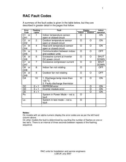
1<strong>RAC</strong> <strong>Fault</strong> <strong>Codes</strong>A summary of the fault codes is given in the table below, but they aredescribed in greater detail in the pages that follow.ErrorCodeFlashingLights<strong>Fault</strong>DisplayIndoor OutdoorIndooroperationC1 or 1 Indoor temperature sensor OONCH1open or closed circuitC2 or 2 Outdoor temperature sensor O O ONCH2open or closed circuitC4 0r 4 Heat sink temperature sensor O O ONCH4open or closed circuitC5 or 5 Communication between indoor O O OFFCH5and outdoor unitsC6 orCH66 Excessive current at inverterDC power circuitO O SHUTDOWNC7 orCH77 Excessive compressor current O O SHUTDOWNC8 or 8 Indoor fan not rotating O OFFCH8C9 or 9 Outdoor fan not rotating O O OFFCH9CA 10 1. Discharge temp more than O O ON130 0 C2. <strong>Fault</strong>y discharge thermistorCC 2 + 1 EEPROM error O ONCD 3 + 1 Inverter module error O ONCE 4 + 1 O ONPoLoSystem in Power Mode – not afaultSystem in test mode – not afaultOONotes:On models with an alpha-numeric display the error codes are as per the left handcolumn above.On other models the fault is determined by counting the number of flashes on one ortwo led’s. There is an interval of three seconds between repeats of the flashingsequence.<strong>RAC</strong> units for Installation and service engineersLGEUK July 2007
70Temperature deg C-10-50510152025303540k OhmsAlternatively the sensor can be tested while still connected to the PCB measure theDC voltage across the resistor and check it against the graph below.Resistance4.5Temperature deg C-10-505101520253035402<strong>Fault</strong> code C1, CH1 or 1 flashIs a fault with the Indoor unit return air ThermistorUnplug the Thermistor from the PCB and Check its resistance check against thisgraph:Resistance of air thermistor10 20 30 40 50 600<strong>RAC</strong> units for Installation and service engineersLGEUK July 2007Voltage across air thermistor2.53 3.54 Volts DC acrosthermistor 2
k OhmAlternatively the sensor can be tested while still connected to the PCB measure theDC voltage across the resistor and check it against the graph below.Resistance4.5 3.54 0 10 20 30 40 Resistance k Ohms -103<strong>Fault</strong> code C2, CH2 or 2 flashesIs a problem with the Indoor unit coil ThermistorUnplug the Thermistor from the indoor PCB and Check its resistance against thisgraph:Coil thermistor resistance10 15 20 25 30 -10 0 10 20 30 40 Temperature deg C 05Voltage across coil thermistor0.51 1.52 2.530<strong>RAC</strong> units for Installation and service engineersLGEUK JulyTemperature deg C2007
70Temperature deg C-10-50510152025303540k OhmsAlternatively the sensor can be tested while still connected to the PCB measure theDC voltage across the resistor and check it against the graph below.Resistance4.5Temperature deg C-10-505101520253035404<strong>Fault</strong> Code C4, CH4 or 4 flashesIs a fault with the Outdoor unit inverter Heat sink Thermistor, the fault will occur if thesensor is faulty or the heat sink temperature exceeds 85ºC ?Unplug the Thermistor from the PCB and Check its resistance check against thisgraph (the air thermistor and heat sink thermistor have the same calibration graph)Resistance of air thermistor10 20 30 40 50 600<strong>RAC</strong> units for Installation and service engineersLGEUK July 2007Voltage across air thermistor2.53 3.54 Volts DC acrosthermistor 2
5<strong>Fault</strong> code C5, CH5 or 5 flashesThis fault code indicates a communication error between the indoor and outdoor units.If there is a communication error fault CH05, will appear within 5 minutes of poweringup the system.Communications between the outdoor and indoor units are via terminal 3 and N ofthe interconnecting cable. Communications errors can be due to:1. Cable and cable connection faults.2. Devices such as an external pump connected to the communicationsterminals3. <strong>Fault</strong>y indoor or outdoor PCBs.If there is a communications error CH05, then first check the terminals at both theindoor and outdoor units for any devices other than the interconnecting cable.Remove such equipment, and connect them elsewhere. If the fault persists, proceedas follows:1. Disconnect the signal cable at both ends (Terminal 3).2. With the INDOOR unit powered up and switched on, check the DC voltage atthe INDOOR unit between the signal (terminal 3) and neutral. Connect the redlead from your meter to 3 and the Black lead to N, the Voltage should benegative, and fluctuating up to about -70 V. If there is no voltage, the indoorPCB is faulty3. With the OUTDOOR unit powered up and switched on, check the DC voltageat the OUTDOOR unit between the signal (terminal 3) and neutral, connectthe red lead from your meter to 3 and the black lead to N, It should be positive,fluctuating up to about +70 V. If there is no voltage, the outdoor PCB is faulty4. If the tests in 2 and 3 above show the correct voltage, the fault lies in theinterconnecting cable. Remove all cores at both ends, and check for openand short circuits, including shorts to earth. Check also that there are noswitches on the signal wire, since poor contact can cause the problem. Checkalso that there are adequate earth connections at both the indoor and outdoorunits.5. When communications are healthy, there should be up to +70V DC betweenthe signal and neutral wires when the unit is running and the interconnectingcable is connected.<strong>Fault</strong> code C6, CH6 or 6 flashesThis fault is caused by an over current in the inverters DC power circuit. This iscaused by either the inverter PCB or compressor being short circuit or down to earth.Check the resistance of the compressor windings with the electrical connectionsdisconnected, typically they should be between 1 and 5 Ohms each.If the compressor is OK check the inverter output voltages are all equal.<strong>Fault</strong> Code C7, CH7 or 7 flashesThis fault is caused by a Compressor over-current see code 06<strong>RAC</strong> units for Installation and service engineersLGEUK July 2007
6<strong>Fault</strong> Code C8, CH8 or 8 flashesThis fault is caused by the Indoor fan being locked;Check the fan motor is plugged into the indoor PCB correctly; check the fan motor isturning, if not check the AC Voltage supplied to the fan motor, this will vary from 120V ac at low speed to 170V AC at high speed.If no Voltage is present the PCB is faulty, if the Voltage is present the fan motor willbe <strong>Fault</strong>y.<strong>Fault</strong> Code C9, CH9 or 9 flashesThis is an Outdoor unit fan motor faultCheck the fan motor is plugged into PCB correctly; Start the unit up the fan motorshould turn when the compressor is running.Check the fan motor is turning, if not check the Voltages supplied to the fan motor,there will be a connector on the PCB with five wires, measure from red to Black, itshould be 300 - 320V DC,From white to Black it should be 10-15V DC,If no Voltage is present the PCB is faulty, if the Voltage is present the fan motor willbe <strong>Fault</strong>y.<strong>Fault</strong> Code CA or 10 flashesThis fault is caused by the compressor discharge sensor reading over 130ºC or thedischarge Thermistor being faulty.Reset the power, if the fault goes away and the compressor starts check thedischarge temperature, if it is very hot check the refrigerant charge. High dischargetemperatures are usually caused by shortage of refrigerant.If the unit wont restart after resetting the power check the Thermistor, Unplug theThermistor from the PCB and Check its resistance check against this graph:<strong>RAC</strong> units for Installation and service engineersLGEUK July 2007
k OhmsAlternatively the sensor can be tested while still connected to the PCB measure theDC voltage across the resistor and check it against the graph below.Resistance4.9 0 10 20 30 40 Voltage DC<strong>Fault</strong> Code CC or 2 + 1 flashes (2 flashes on one led, 1 flash on another)-107Resistance of discharge thermistor150 200 250 300 350 400 450 500 550 600 -10 0 10 20 30 40 Temperature deg C 100Voltage across discharge thermistorCheck the correct PCB assembly has been installed, check for dry joints, replaceoutdoor unit PCB if nothing is found.<strong>Fault</strong> Code CD or 3 + 1 flashes (3 flashes on one led, 1 flash on another)<strong>RAC</strong> units for Installation and service engineersLGEUK July 20074.3 4.4 4.5 4.6 4.7 4.84.2Temperature deg CThis fault indicates a problem with the inverter module, see section on testinginverters. Also check reactor is connected to the PCB and check its resistance itshould be well under 1 Ohm.

