geothermal power plant projects in central america - Orkustofnun
geothermal power plant projects in central america - Orkustofnun
geothermal power plant projects in central america - Orkustofnun
- No tags were found...

Create successful ePaper yourself
Turn your PDF publications into a flip-book with our unique Google optimized e-Paper software.
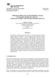
Second, condensation of the work<strong>in</strong>g fluid vapor can be calculated as̅ = (h −h ) (34)where h is the enthalpy of the work<strong>in</strong>g fluid <strong>in</strong> a saturated vapor state, where the p<strong>in</strong>ch po<strong>in</strong>t <strong>in</strong>the condenser is located. Figure 18 shows the thermodynamic T-s diagram of the process.FIGURE 18: T-s diagram of an ORC cycle (Isopentane) with regeneration4.2 Simulation and optimizationCentral America is a small geographic region divided politically <strong>in</strong>to many territories. There existsimilar economic and climatic conditions for the design of <strong>geothermal</strong> <strong>plant</strong>s. However, <strong>geothermal</strong>reservoir and well properties differ from site to site and, as such, require serious attention dur<strong>in</strong>g thedesign process as they are critical parameters for optimization. In this analysis, <strong>power</strong> <strong>plant</strong> models forCentral America were designed based on the technical parameters which do not change from case tocase and on the similar climatic conditions of the region.The methodology applies the fundamental pr<strong>in</strong>ciples of thermodynamics to the components of thecycle and to the cycle itself to form a system of non l<strong>in</strong>ear equations as developed <strong>in</strong> Section 4.1. Theoptimization process was solved by us<strong>in</strong>g the mathematical environment called Eng<strong>in</strong>eer<strong>in</strong>g EquationSolver (EES) which also evaluates thermodynamic properties and solves a system of non l<strong>in</strong>earequations.The optimization process was done over three types of energy conversion systems: s<strong>in</strong>gle flash (SF),double flash (DF) and organic Rank<strong>in</strong>e cycle (ORC). For each of these cycles design variables andconstra<strong>in</strong>ts were def<strong>in</strong>ed. The optimization constra<strong>in</strong>ts were applied by sett<strong>in</strong>g boundaries on eachvariable. In this analysis, the optimization process was carried out on the design variables us<strong>in</strong>g adirect search algorithm called the grid search method.Accord<strong>in</strong>g to Rao (2009) the method <strong>in</strong>volves sett<strong>in</strong>g up a suitable grid <strong>in</strong> the design space, evaluat<strong>in</strong>gthe objective function at all the grid po<strong>in</strong>ts, and the po<strong>in</strong>t correspond<strong>in</strong>g to the best objective functionvalue is considered the optimum solution. The <strong>power</strong> output optimization process was repeated severaltimes <strong>in</strong> each case for different resource temperatures and mass flows.4.2.1 Assumptions and limitationsSimulation of the models of the energy conversion systems described <strong>in</strong> Section 4.1 requiredassumptions for a wide range of behavior of the <strong>geothermal</strong> system and technical characteristics of the<strong>power</strong> <strong>plant</strong> equipment. Table 3 gives a summary of assumptions used as <strong>in</strong>put <strong>in</strong> this analysis. Someimportant assumptions not used as <strong>in</strong>put for the analysis are:22