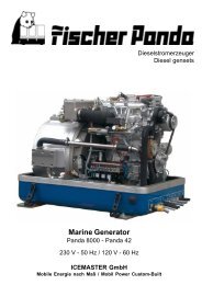
Marine Generator Panda PMS 12 mini E-TEC Icemaster Fischer ...
Marine Generator Panda PMS 12 mini E-TEC Icemaster Fischer ...
Marine Generator Panda PMS 12 mini E-TEC Icemaster Fischer ...
- No tags were found...

Create successful ePaper yourself
Turn your PDF publications into a flip-book with our unique Google optimized e-Paper software.
25 20 10 10 10since 1977<strong>Icemaster</strong> GmbHsince 1978<strong>Fischer</strong> <strong>Marine</strong><strong>Generator</strong>ssince 1988Conclusion <strong>Fischer</strong> -<strong>Icemaster</strong> GmbHsince 1988100 % water cooled<strong>Panda</strong> generatorssince 1988<strong>Panda</strong> Vehicle<strong>Generator</strong>s<strong>Fischer</strong> <strong>Panda</strong>FISCHER GENERATORS have been manufactured since 1978 and are a well-known brand for first class diesel generatorswith especially effective sound-insulation.<strong>Fischer</strong> has been one of the leading manufacturers in respect of quality and know-how during this period.FISCHER, as the worldwide manufacturer of modern marine diesel generators, developed the Sailor-Silent series forexample and produced a GFK sound-insulated capsule as early as 1979 and the basis for new generator technology.The companies <strong>Fischer</strong> and <strong>Icemaster</strong> amalgamated under the direction of <strong>Icemaster</strong> in 1988, in order to concentrateon the development of new products. Production was moved to Paderborn.The amalgamation of the two qualified companies led to the development of a complete new programme within a shortspace of time. The gensets developed at that time set new technological standards worldwide.The gensets became more efficient and powerful than other gensets in the same nominal performance range, becauseof the improved cooling. <strong>Panda</strong> generator demonstrated its superiority in several tests by renowned institutes andmagazines during the past years. The patented VCS (voltage Control System) means it can meet all demands includingmotor speed. The start-booster (ASB) means <strong>Panda</strong> generators meet the highest demands in respect of voltage stabilityand starting values A <strong>Panda</strong> generator, with the same drive motor, produces 15% more effective output than themajority of conventional generators. This superiority in efficiency also ensures a fuel saving to the same extent.The 100% water-cooled <strong>Panda</strong> genset are currently manufactured in the performance range from 2 to 100 kW invarious versions. Fast running motors are preferred for performances up to approx 30 kW (Nominal speed 3000 rpm).The heavier slow runners are preferred for the higher range. The fast running gensets have proved themselves manytimes for many uses, that they meet the demands in quality of yachts and vehicles, and offer space and weight savingof 50% compared to slow running generators.In addition to the <strong>Panda</strong> series, <strong>Icemaster</strong> also supply the super compact high-tech sound-insulated battery charginggenset from the DC/AC <strong>Panda</strong> AGT series, which is a very interesting solution for the production of mobile power.The new HTG-alternators ensure that a charging rate of 285 amps is achieved that was scarcely thought possible forthis compact construction. This alternator replaces a separate shipboard generators (constant 230 volts AC with up to3500 kW from the main machine)ICEMASTER GmbH, 33104 Paderborn, reserves all rights regarding text and graphics. Details are given to the best of our knowledge. No liability is accepted for correctness.Technical modifications for improving the product without previous notice may be undertaken without notice. Before installation, it must be ensured that the Pictures,diagrams and related material are applicable to the genset supplied. Enquiries must be made in case o doubt.iii
CALIFORNIAProposition 65 WarningDiesel engine exhaust and some of its constituentsare known to the State of California to cause cancer,birth defects, and other reproductive harm.Attention, Important Directions regarding Operation!1. The installation certificate must be completed when taken into use, and certified by a signature.2. The installation certificate must be despatched within two weeks of use to ICEMASTER.3. The official guaranty confirmation will be completed by ICEMASTER after receipt and sent to the customer.4. A guaranty must be shown to make any claims.Claims against the guaranty will not be accepted of the above said instructions are not, or only partially, carried out.Manufacturer declaration in terms of the machine guideline 98/37/EG .The generator is in such a way developed that all assembly groups correspond to the CE guidelines. If machine guideline98/37/EG is applicable, then it is forbidden to bring the generator into operation until it has been determinedthat the system into which the generator is to be installed in also corresponds to the regulations of the machine guideline98/37/EG. This concerns among other things the exhaust system, cooling system and the electrical installation.The evaluation of the "protection against contact" can only be accomplished in connection with the respectivesystem. Likewise among other things responsibility for correct electrical connections, a safe ground wire connection,foreign body and humidity protection, protection against humidity due to excessive condensation as well as the overheatingthrough appropriate and inappropriate use in its installed state on the respective machine lies within theresponsibility of those who undertake installation of the generator in the system.Use the advantages of the customer registration:• Thus you receive to extended product informations, which are sometimes safety-relevant• you receive, if necessarily free UpgradesFar advantages:By your full information <strong>Fischer</strong> <strong>Panda</strong> technicians can give you fast assistance, since 90% of the disturbances resultfrom errors in the periphery.Problems due to errors in the installation can be recognized in the apron.Technical Support per Internet:info@fischerpanda.comiv
Safety InstructionsThe electrical Installations may only be carried out be trained andtested personnel!The generator may not be taken into use with the cover removed.The rotating parts (belt-pulley, belts, etc) must be so covered and protected do that there is no danger to life andbody!If a sound insulation covering must be produced at the place of installation, then well-placed signs must show thatthe generator can only be switched on with a closed capsule.All servicing-, maintenance or repair work may only carried out, when the motor is not running.Electrical voltages above 48 volts ( battery chargers greater than 36 volts) are always dangerous to life). The rules ofthe respective regional authority must be adhered to. Only an electrician may carry out installation of the electricalconnections for safety reasons.Protective Conductor:The generator is „earthed " as standard (The centre and earth are connected by means of a bridge in the generatorterminal box). This is a basic safety function, which offers basic safety as long as no other component has beeninstalled. It is, above all, conceived for supply and an eventual test run.This "earth" (PEN) is only effective, if all parts of the electrical system is earthed, and has a common “potential”. Thebridges can be removed, if this is required for technical reasons and another protection system has been installed.The full voltage is exploited at the AC control box, when the generator is run. It must therefore be ensuredthat the control box is closed and cannot be tampered with, if the generator is running.The battery must always be disconnected, if work on the generator or electrical system is to be carried out,so that the generator cannot be unintentionally started.It is not allowed to disconnect the battery during operation!After the generator has stopped the battery can be disconnected!Switch off all load when working on the generatorAll load must be disconnected, in order to avoid damages to the devices. In addition the semi conductors in the ACcontrol box must be disconnected in order to avoid the boat capacitors being activated. The minus pole of the batteryought to be removed.Capacitors are required to run the generator. These have two varying functions:A) The working capacitorsB) The (Booster) capacitorsBoth Groups are located in the sound cover of the genset.Capacitors are electrical stores. There could be a residual of high electrical current at the contacts for a period disconnectionfrom the circuit. The contacts my not be touched for safety reasons, If the capacitors are to be exchangedor checked, then a short circuit between the contacts should be made so that the stored energy is discharged.If the generator is switched off in the normal manner, the working capacitors are automatically discharged by meansof the windings. The booster capacitors are discharged by means of internal discharge resistors.All capacitors must be short-circuited before work is carried out on the AC-Control box for safety reasons.v
Table of ContentsA Mode of Operation of the <strong>Generator</strong> ................................................................................5A.1 Mode of Operation of Operating Surveillance .................................................................... 5A.1.1 Regulation of the generator voltage by the VCS ....................................................................... 9A.1.2 Overloading of engine during longer operation ......................................................................... 9A.1.3 Use the fuel purge switch for fuel delivery............................................................................... 10A.2 Operation of electric motors with high starting current .................................................. 10A.2.1 General references.................................................................................................................. 10A.2.2 Compensation of 1 phases engines ........................................................................................ 10A.2.3 Compensation of 3 phases engines ........................................................................................ 10A.3 Operation of the generator with additional units ............................................................. 11A.3.1 General references.................................................................................................................. 11A.4 Operation of the generator with HTG generator ............................................................... 11A.4.1 General references.................................................................................................................. 11A.5 Operation of the generator with automatic start .............................................................. <strong>12</strong>A.6 Operation of the generator with installation under the waterline ................................... <strong>12</strong>A.6.1 Control of the vent valve.......................................................................................................... 13A.7 Operation of the generator with installation over the waterline ..................................... 13B Maintenance Instructions ................................................................................................15B.1 General maintenance instructions .................................................................................... 15B.1.1 Checks before starting ............................................................................................................ 15B.1.2 Hose elements and rubber formed component in the sound cover......................................... 15B.2 Oil circuit maintenance ....................................................................................................... 15B.2.1 Execution of an oil change ...................................................................................................... 16B.3 Checking the water separator in the fuel supply ............................................................. 18B.3.1 De-aerating the fuel system .................................................................................................... 18B.3.2 Exchange of the fuel filter........................................................................................................ 20B.3.3 Exchange the air filter.............................................................................................................. 21B.4 De-aerating of the coolant circuit / freshwater ................................................................. 22B.4.1 Draining the coolant ................................................................................................................ 24B.4.2 Exchange of the v-belt for the internal cooling water pump .................................................... 24B.5 The raw water circuit ........................................................................................................... 26B.5.1 Clean raw water filter............................................................................................................... 26B.6 Causes with frequent impeller waste ................................................................................ 26B.6.1 Exchange of the impeller......................................................................................................... 27B.7 Coolant connection block at generator housing .............................................................. 29B.8 Conservation at longer operation interruption ................................................................. 30B.8.1 Measures on preparation of the winter storage....................................................................... 30B.8.2 Initiation at spring .................................................................................................................... 31C <strong>Generator</strong> Failure .............................................................................................................33C.1 Tools and measuring instruments ..................................................................................... 33C.2 Overloading the <strong>Generator</strong> ................................................................................................. 33C.2.1 Monitoring the <strong>Generator</strong> Voltage ........................................................................................... 3419.4.05 <strong>Panda</strong> <strong>PMS</strong> <strong>12</strong><strong>mini</strong> E-<strong>TEC</strong>_Manual s00760.V01 - Table of contents - Page 1
C.2.2 Automatic Voltage Monitoring and Auto-Shut Down .............................................................. 34C.3 Adjusting Instructions for the Spindle of the actuator ....................................................35C.3.1 Adjustment of the maximum engine speed: ........................................................................... 36C.3.2 Adjustment of <strong>mini</strong>mum engine speed ................................................................................... 37C.3.3 Lubrication of the spiral thread spindle................................................................................... 37C.3.4 Overload damage to the actuator mechanism........................................................................ 38C.4 Low <strong>Generator</strong>-Output Voltage ..........................................................................................40C.4.1 Discharge the capacitors ........................................................................................................ 40C.4.2 Checking the capacitors ......................................................................................................... 40C.4.3 Checking the generator voltage.............................................................................................. 41C.4.4 Measuring the coil resistance ................................................................................................. 41C.4.5 Checking the coil(s) to short-circuit ........................................................................................ 42C.4.6 Measuring the inductive resistance ........................................................................................ 42C.5 <strong>Generator</strong> provides no Voltage ..........................................................................................43C.5.1 Rotor Magnetism Loss and "Re-magnetizing"........................................................................ 43C.6 Starting Problems ................................................................................................................43C.6.1 Fuel Solenoid Valve................................................................................................................ 43C.6.2 Stop solenoid.......................................................................................................................... 44C.6.3 Troubleshooting Table............................................................................................................ 45D Installation Instruction .................................................................................................... 47D.1 Placement .............................................................................................................................47D.1.1 Placement and Basemount .................................................................................................... 47D.1.2 Notice for optimal sound insulation......................................................................................... 47D.2 <strong>Generator</strong> Connections - Scheme ......................................................................................48D.3 Cooling System Installation - Raw water ..........................................................................49D.3.1 General References ............................................................................................................... 49D.3.2 Quality of the raw water sucking in line .................................................................................. 49D.3.3 Installation above waterline .................................................................................................... 49D.3.4 Installation below waterline..................................................................................................... 50D.3.5 Genset housing cooled by raw water ..................................................................................... 51D.4 The Freshwater - Coolant Circuit .......................................................................................52D.4.1 Position of the external Cooling Water Expansion Tank ........................................................ 52D.4.2 De-aerating at the first filling of the internal cooling water circuit ........................................... 52D.4.3 Filling and de-aerating of the internal cooling water circuit..................................................... 54D.4.4 Pressure test for control of cooling water circuit..................................................................... 55D.4.5 Scheme for freshwater circuit at two circuit cooling system ................................................... 56D.5 Watercooled Exhaust System ............................................................................................57D.5.1 Installation of the standard exhaust system ........................................................................... 57D.5.2 Exhaust / water separator....................................................................................................... 58D.5.3 Installation exhaust/water separator....................................................................................... 59D.6 Fuel System Installation .....................................................................................................60D.6.1 General References ............................................................................................................... 60D.6.2 The electrical fuel pump ......................................................................................................... 61D.6.3 Connection of the fuel lines at the tank .................................................................................. 62D.6.4 Position of the pre-filter with water separator ......................................................................... 62D.7 <strong>Generator</strong> <strong>12</strong>V DC System-Installation ..............................................................................62D.7.1 Connection of the <strong>12</strong>V starter battery..................................................................................... 63D.7.2 Installation of the remote control panel................................................................................... 64D.7.3 The speed sensor................................................................................................................... 64Page 2 <strong>Panda</strong> <strong>PMS</strong> <strong>12</strong><strong>mini</strong> E-<strong>TEC</strong>_Manual s00760.V01 - Table of contents 19.4.05
D.7.4 Electronic starter control unit................................................................................................... 65D.8 <strong>Generator</strong> AC System-Installation ..................................................................................... 66D.8.1 Installation scheme.................................................................................................................. 66D.8.2 Control box .............................................................................................................................. 68D.8.3 VCS-voltage control ................................................................................................................ 68D.8.4 Measuring board ..................................................................................................................... 70D.9 Insulation test ...................................................................................................................... 70D.10 Instructions on preventation of galvanic corrosion ........................................................ 71ETables ...................................................................................................................................IE.1 Troubleshooting ..................................................................................................................... IE.2 Technical data ......................................................................................................................VIE.3 Types of coil ........................................................................................................................VIIE.4 Inspection checklist for services ......................................................................................VIIIE.5 Engine oil ..............................................................................................................................IXE.6 Coolant specifications ..........................................................................................................XE.7 Scheme VCS board ..............................................................................................................XIE.7.1 Legend VCS board.................................................................................................................. XIE.8 Scheme measuring board ................................................................................................ XIVE.8.1 Legend measuring board ...................................................................................................... XIVE.9 Scheme relay board (front side) ....................................................................................... XVE.9.1 Legend relay board ............................................................................................................... XVI19.4.05 <strong>Panda</strong> <strong>PMS</strong> <strong>12</strong><strong>mini</strong> E-<strong>TEC</strong>_Manual s00760.V01 - Table of contents - Page 3
Page 4 <strong>Panda</strong> <strong>PMS</strong> <strong>12</strong><strong>mini</strong> E-<strong>TEC</strong>_Manual s00760.V01 - Table of contents 19.4.05
Mode of Operation of the <strong>Generator</strong>A. Mode of Operation of the <strong>Generator</strong>A.1 Mode of Operation of Operating SurveillanceInternal monitoring switchesThe generator is equipped about failure switches, which are indicated on the remote controlpanel, and also about failure switch, which switch-off the generator automatically without indicatinga failure in the remote control panel:The remote control panel supervised the following values. In the case of a disturbance the generatoris switched off, in order to avoid damage to the genset:1. Cooling water temperature at cylinder head, at exhaust manifold and exhaust connection2. Raw water and fresh water temperature3. Coil temperature4. Oil pressureThe fault is transmitted, if one of these switches measures a value that exceeds the requiredvalue (all switches are openers). The current is switched off by the main relay. (Fuel magnetvalve closes, the fuel suction pump is switched off, VCS is switched off).The combustion engine possesses an oil pressure control switch, which switches the engine off ifthe oil pressure drops under a certain value.The additional failure switch in the generator coil, it is also indicated at the remote control panel,interrupts directly the current supply to the main power relay. By this constellation it is guaranteedthat the generator switches off in each case when an error is present.This measure is, if possibly, a circuit at the remote control panel failed.Thermo-switch at cylinder headThe thermo-switch at the cylinder headserves the monitoring of the generatortemperature. All thermo-switches for thegenerators from <strong>Panda</strong> 6.000 upward aretwo-pole and laidout as "openers".110°C and 130°CFig. A.1: Thermo-switch at cylinder head19.4.05 <strong>Panda</strong> <strong>PMS</strong> <strong>12</strong><strong>mini</strong> E-<strong>TEC</strong>_Manual s00760.V01 - Chapter A: Mode of Operation of the <strong>Generator</strong> Page 5
Mode of Operation of the <strong>Generator</strong>Thermo-switch in the generator coil<strong>12</strong>31. <strong>Generator</strong> coil2. Thermo-switch 4x165°C3. HousingFor the protection of the generator coilthere are two thermo-switches inside thecoil, which are for inserted parallel andsafety's sake independently from eachother.Fig. A.2: Coil thermo-switchThermo-switch at the grease lubricatedbearingThe generator bearing is equipped with anoil thermoswitch, which switches theengine off if the oil temperature becomesto high.130°CFig. A.3: Thermo-switch at front plateThermo-switch at water-cooledexhaust elbow<strong>12</strong>0°C/105°CFig. A.4: Thermo-switch at exhaust elbowPage 6 <strong>Panda</strong> <strong>PMS</strong> <strong>12</strong><strong>mini</strong> E-<strong>TEC</strong>_Manual s00760.V01 - Chapter A: Mode of Operation of the <strong>Generator</strong> 19.4.05
Mode of Operation of the <strong>Generator</strong>Thermo-sensor exhaust portFig. A.5: Thermo-sensor exhaust portThermo-sensor raw water inFig. A.6: Thermo-sensor raw water inThermo-sensor raw water outFig. A.7: Thermo-sensor raw water out19.4.05 <strong>Panda</strong> <strong>PMS</strong> <strong>12</strong><strong>mini</strong> E-<strong>TEC</strong>_Manual s00760.V01 - Chapter A: Mode of Operation of the <strong>Generator</strong> Page 7
Mode of Operation of the <strong>Generator</strong>Thermo-sensor fresh water inFig. A.8: Thermo-sensor fresh water inThermo-sensor fresh water outFig. A.9: Thermo-sensor fresh water outOil sensor with oil pressure switch<strong>12</strong>In order to be able to monitore the lubricatingoil system, an oil pressure switch isbuilt into the system. The oil pressureswitch is on the back of the engine (belowthe oil filter).1. Oil sensor2. Oil pressure switchFig. A.10: Oil sensor with oil pressure switchPage 8 <strong>Panda</strong> <strong>PMS</strong> <strong>12</strong><strong>mini</strong> E-<strong>TEC</strong>_Manual s00760.V01 - Chapter A: Mode of Operation of the <strong>Generator</strong> 19.4.05
Mode of Operation of the <strong>Generator</strong>Oil sensor at oil sumpFig. A.11: Oil sensor at oil sumpA.1.1 Regulation of the generator voltage by the VCSThe output voltage of the generator is permanently measured by the VCS (approx. 20 times persecond!). As soon as by a load the voltage is affected, the speed regulation provides to adapt tothe changed power demand by appropriate change of the engine speed.Not only by the excitation of the generator it is worked against to the initiating voltage drop, butalso by the raising of the number of revolutions whereby the drive potential improves.A.1.2 Overloading of engine during longer operationPlease ensure that the genset is not overloaded. Overloading occurs when the electrical load(demand) induces a load torque in the generator which is higher than that which the diesel drivemotor can provide. Overloading causes the engine to run rough, burn oil, creates excessiveexhaust (environmentally unfriendly) and even to stall. Extra caution should be practised withmulti-power units (single and 3-phase current generation) to avoid overloading the diesel driveengine.The generator should only be loaded at the peak rated power forshort periods only! A high peak current is required to start manyelectrical devices, especially electric motors and compressors (froma still stand state).The height of the rated output (P) can taken from the identificationplate attached on the housing.In order to guarantee a long life span, the continuous load shouldnot exceed 80% of the nominal load. By continuous output weunderstand the continuous operation of the generator over manyhours. It is harmless for the engine to supply for 2-3 hours the fullrated output.The total conception of the <strong>Panda</strong> generator guarantees that the continuous load operation doesnot release superelevated temperatures of the engine also with extreme conditions. It is to beconsidered that the exhaust gas values in the full load operation become more unfavorable (sootformation).19.4.05 <strong>Panda</strong> <strong>PMS</strong> <strong>12</strong><strong>mini</strong> E-<strong>TEC</strong>_Manual s00760.V01 - Chapter A: Mode of Operation of the <strong>Generator</strong> Page 9
Mode of Operation of the <strong>Generator</strong>A.1.3 Use the fuel purge switch for fuel deliverySwitch on the "Stand by"-switch at thecontrol panel. Functional elements mustshine.Press „Fuel purge“-switch S2 (located atthe air suction housing) and hold. Theelectrical fuel pump must run audibly. Thepressing of the switch become audibleswitching on and off of the fuel solenoidvalve at the generator (with removedsound cover).A.2 Operation of electric motors with high starting currentA.2.1 General referencesElectric motors can need for a very short time an increased starting current when starting. Thestarting current can amount to up to 10 times of the rated current. This applies in particular to 2-pole engines and particularly to fan engines with larger power, in addition, to engines, which compressorwith flywheels or the like propels. If such engines are to be operated, contact the technicianof <strong>Fischer</strong> <strong>Panda</strong>, in order to find suitable measures, which work against the high startingcurrent and/or layout the generator for the higher starting current.A.2.2 Compensation of 1 phases enginesIf inductive electrical load is connected, then there is a phase shift between current and voltage;the portion of the blind current becomes larger. This effect meets by automatic activating of additionalcapacitors and compensates the idle current. This compensation of the inductive load causesthat the efficiency of the generator is increased. By the automatic compensation can moreengines or a larger electrical load with an inductive character be operated. In other words: theusable power of the generator is increased.A.2.3 Compensation of 3 phases enginesSee folding sheet "Operation Instructions for <strong>Generator</strong> with Inductive Loads"Page 10 <strong>Panda</strong> <strong>PMS</strong> <strong>12</strong><strong>mini</strong> E-<strong>TEC</strong>_Manual s00760.V01 - Chapter A: Mode of Operation of the <strong>Generator</strong> 19.4.05
Mode of Operation of the <strong>Generator</strong>A.3 Operation of the generator with additional unitsA.3.1 General referencesThe <strong>Panda</strong> generator is arranged that the operation of additional gensets, which are flanged ondirectly to the front cover of the generator, is possible. If such gensets are intended, this - if possible- should be considered with the order of the generator. With the mounting of additionalhydraulic pumps the employment of an electrical separation clutch is always recommended. Theappropriate components are available for the different generator types. It is caused that the additionalhydraulic pump is in operation even if it is actually used.Depending upon power of the additionally appropriate gensets the power is reduced, which canput the combustion engine to the generator at the disposal.<strong>Panda</strong> generator with electrically adjustableclutchA.4 Operation of the generator with HTG generatorA.4.1 General referencesBeside the alternating current gensets ICEMASTER supplies also the super-compact High techbattery load gensets from the series of PANDA AGT in sound-insulated construction, whichrepresent a very interesting alternative solution in a DC-AC power technology merged for generationof current within the mobile range.The new HTG generators with 280 A charging current offer themselves a alternative for an onboardcurrent generator, if a diesel set is not intended. These generators differ according to thetechnology very substantially from all conventional products. The size is so compact that you canexchange it also against a generator according to standard. This generator can ensure a 230Valternating current supply up to 3.000W power in connection with a PANDA HD inverter also incontinuous operation.19.4.05 <strong>Panda</strong> <strong>PMS</strong> <strong>12</strong><strong>mini</strong> E-<strong>TEC</strong>_Manual s00760.V01 - Chapter A: Mode of Operation of the <strong>Generator</strong> Page 11
Mode of Operation of the <strong>Generator</strong>A.5 Operation of the generator with automatic startIf the generator set were set up far away from the location of the remote control panel that theuser cannot hear surely, whether the generator starts, a automatic starting option (accessories)should be installed. With this option the starter is disengaged automatically, if the starting speedis exceeded.A.6 Operation of the generator with installation under thewaterlineIf the generator cannot be installed clearly at least 600mm over the waterline, a vent valve mustbe installed into the raw water line. At installation beside the "midship´s line" a possible heelingmust be considered!The water hose in the sound cover is split on the pressure side of the pump and extended in eachcase in the sound cover at both ends with a connecting nipple by a hose end. Both hose endsmust led out from the sound cover to a point, which is at least for 600mm over the waterline (ifpossible in the midship´s line). The valve is inserted at the highest place, at least 600mm over thewaterline.Cut the hose rubber for the external valve vent........and bent it upwards.Both hose ends must be led out outside ofthe sound cover to one point, if possible600mm over the waterline in the midshipline. The valve is connected at the highestplace with the two hose ends.Page <strong>12</strong> <strong>Panda</strong> <strong>PMS</strong> <strong>12</strong><strong>mini</strong> E-<strong>TEC</strong>_Manual s00760.V01 - Chapter A: Mode of Operation of the <strong>Generator</strong> 19.4.05
Mode of Operation of the <strong>Generator</strong>A.6.1 Control of the vent valveIf the valve is blocked, the cooling water pipe cannot be ventilated after the stop of the generator,the water column is not interrupted and the water can penetrate into the combustion chamber ofthe engine.This lead to destruction of the engine!A.7 Operation of the generator with installation over the waterline<strong>Generator</strong> over the waterline:If the generator is installed over the waterline, a stronger impeller wear is possible, the pump canrun after the start some seconds dry.It is very important that the impeller is exchanged every few months. When starting the generatorattention should be always paid and heard to it, when raw water withdraws from the exhaustneck. If this takes longer than 5 seconds the impeller must exchanged, he sucks in air before rawwater reaches the impeller (see picture below) and the impeller then wears strongly. In this casethe impeller loses his effect and raw water can penetrate into the engine as well as substantiallydestroy it. If the impeller is not exchanged early enough, the entire pump must be replaced.Otherwise the impeller wings breaks in pieces and it stresses some time to remove these again.Replacement impeller should always be on board.With the installation of the generator it must be paid attention that the impeller pump is wellaccessible, since the impeller is a wearing part. If this place at the location can be reached notwell, an external pump with electric drive can be used instead of the pump built firmly in the soundcover, which should be installed in a well accessible place.1. Raw water filter2. Water cock3. Hull inletMake certain that the raw waterfilter lies above the water level,otherwise with cleaning watercan penetrate by the hull inlet.An external pre-pump canrelieve the impeller.<strong>12</strong>319.4.05 <strong>Panda</strong> <strong>PMS</strong> <strong>12</strong><strong>mini</strong> E-<strong>TEC</strong>_Manual s00760.V01 - Chapter A: Mode of Operation of the <strong>Generator</strong> Page 13
Mode of Operation of the <strong>Generator</strong>Page 14 <strong>Panda</strong> <strong>PMS</strong> <strong>12</strong><strong>mini</strong> E-<strong>TEC</strong>_Manual s00760.V01 - Chapter A: Mode of Operation of the <strong>Generator</strong> 19.4.05
Maintenance InstructionsB.2.1 Execution of an oil changeOil drain hoseFor the oil change an oil drain hose is leadthrough the sound cover.Oil drain screwThe oil can be discharged by opening theoil drain screw. For countering use asecond wrench.17Oil drain pumpIf discharging of the oil is not possible, werecommend the employment of a handpump, which can be attached to the oildrain hose.Afterwards the oil drain screw is closedagain.Page 16 <strong>Panda</strong> <strong>PMS</strong> <strong>12</strong><strong>mini</strong> E-<strong>TEC</strong>_Manual s00760.V01 - Chapter B: Maintenance Instructions 19.4.05
Maintenance InstructionsOil filter changeThe oil filter can be loosen with an oil filterstrap.Oil filter gasketBefore the insertation of the new oil filterthe gasket should be coated with somethingoil.Tighten the oil filter only by hand.Open the oil filler neckAfter opening the cap of the oil filler neckthe new oil is refilled.Please wait instant, before measure the oillevel, the oil must set off in the sump.19.4.05 <strong>Panda</strong> <strong>PMS</strong> <strong>12</strong><strong>mini</strong> E-<strong>TEC</strong>_Manual s00760.V01 - Chapter B: Maintenance Instructions Page 17
Maintenance InstructionsOil dipstickWith the help of the engine oil dipstick theoil level is to examined. The prescribed fillinglevel may not exceed the „Max“ marking.We recommend 2/3 oil level.B.3 Checking the water separator in the fuel supplyThe pre-filter with water separator has acock at its lower surface, with this cock thedownward sunk water can be discharged.This is simply possible, water is heavierdue to its density than the Diesel.B.3.1 De-aerating the fuel systemNormally, the fuel system is designed to bleed out air itself i.e. as soon as the electric startermotor starts operation the fuel pump starts working and the fuel system will be de-aerated aftersome time automatically. It is nevertheless essential to bleed the system as follows prior to thefirst operation (as all hoses are empty):1. Switch the main „Stand by“ switch on control panel to „ON“. Functional components must illuminate.Page 18 <strong>Panda</strong> <strong>PMS</strong> <strong>12</strong><strong>mini</strong> E-<strong>TEC</strong>_Manual s00760.V01 - Chapter B: Maintenance Instructions 19.4.05
Maintenance Instructions2. Push „Fuel purge“- switch and holdtight. The electric fuel pump has to berunning audibly. By moving the switchyou can hear the solenoid valve of thegenerator starting and stopping (whenthe sound cover is taken off).3. After the fuel pump has been running 3to 4 minutes because the failurebypass switch has been pushed downthe bleeding screw of the solenoidvalve has to be unscrewed. When openingthe screw one has to carry onpushing the switch. To avoid fuel gettingin the sound cover a piece of clothor absorbent paper should be putunder the connection. As soon as fuelis running out without bubbles the airbleeding screw can be screwed inagain. Now stop pushing the switch.104. Now the unit can be started by pushingthe "Run/Stop"-button. The unit shouldstart after a short while.5. Should the unit not start the pipe unionnuts of the injection nozzles has to beloosen and try again to start the unit.After the unit has started the pipe unionnut has to be tightened again.6. „Stand by“-switch "OFF".1719.4.05 <strong>Panda</strong> <strong>PMS</strong> <strong>12</strong><strong>mini</strong> E-<strong>TEC</strong>_Manual s00760.V01 - Chapter B: Maintenance Instructions Page 19
Maintenance InstructionsB.3.2 Exchange of the fuel filterFilter replacement depends on the amount of fuel contamination build up, but should take place,as a <strong>mini</strong>mum, every 300 operation hours.0101. Fuel filter housing02. Fuel filter element03. See-through bowl0203Spin the bowl (03) from the mountinghead (01) by hand.Spin the filter element (02) from the mountinghead (01).Page 20 <strong>Panda</strong> <strong>PMS</strong> <strong>12</strong><strong>mini</strong> E-<strong>TEC</strong>_Manual s00760.V01 - Chapter B: Maintenance Instructions 19.4.05
Maintenance InstructionsTighten the new filter element (02) firmlyto the mounting head (01).Lube the o-ring for the bowl with a temperatureresistant safety grease (specification:Anti-Seize). Tighten the bowl (03) tothe mounting head (01).B.3.3 Exchange the air filterOpen the air suction housing by loosen thesix screws on the housing cover.8Change the air filter mat19.4.05 <strong>Panda</strong> <strong>PMS</strong> <strong>12</strong><strong>mini</strong> E-<strong>TEC</strong>_Manual s00760.V01 - Chapter B: Maintenance Instructions Page 21
Maintenance InstructionsB.4 De-aerating of the coolant circuit / freshwaterSpecial notes for the ventilation of the cooling systemIf the cooling water is drained or if other air should have arrived into the cooling system, it isnecessary to de-aerate the cooling system. This de-aerate procedure must be repeated severaltimes:ATTENTION ! Before opening the de-aeratingpoints the generator must be stagnant !!!Pay attention that the external coolant expansiontank is connected with the generator by the twointended connection points.Further it should be guatanteed that the expansiontank is attached in sufficient height (600mm9over the level of the generator exhaust elbowunion.Open de-aerating screw at the coolingwater pump.10Open de-aerating screw at the thermostathousing10Page 22 <strong>Panda</strong> <strong>PMS</strong> <strong>12</strong><strong>mini</strong> E-<strong>TEC</strong>_Manual s00760.V01 - Chapter B: Maintenance Instructions 19.4.05
Maintenance InstructionsFill in cooling water into the cooling waterfiller neck. If it is to be recognized that thecooling water level does not fall anymore(with cold cooling water the cooling waterlevelmust cover the sheet metal in theexhaust elbow), close the filler-cap andthe cooling water screws and start thegenerator.Now the cooling water is only filled over the external expansion tank. This is connected by 2hoses with the genset.The external expansion tank should be filled in the cold condition only up to maximally20%. It is very important that a large extension space over the cooling water level remains.Repeat this procedure several times.If no change of the cooling water level can be determined, the generator is started for 5 minutes.Afterwards repeat the de-aeration two - three times.It is meaningful to repeat the de-aeration procedure also after some days again to guarantee thatin the system remained bubbles are removed.The de-aerating screw over the housing ofthe cooling water pump may be openedunder no circumstances, while the generatorruns. If this happens inadvertently,through the opening air is sucked in. Avery complex de-aerationt of the entiresystem is necessary thereafter.19.4.05 <strong>Panda</strong> <strong>PMS</strong> <strong>12</strong><strong>mini</strong> E-<strong>TEC</strong>_Manual s00760.V01 - Chapter B: Maintenance Instructions Page 23
Maintenance InstructionsB.4.1 Draining the coolantIn principle only describes here, how the cooling water of the raw water cycle can be drained. Themixture of the fresh water circuit should not be drained in principle. See measures for the preparationof the winter storage.The simplest and cleanest method consists of the fact to bring the external vent valve below thegenerator level and hold over a collecting basin. Open the valve now, the water from the rawwater circuit flows downward into the container.B.4.2 Exchange of the v-belt for the internal cooling water pumpThe relative high ambient temperature in the closed sound insulated capsule (about 85°C) can bea reason for a reduced lifespan of the v-belts. It is possible that the "softener" in the rubber compoundlose their effect after a short operating time because the air in the sound insulated capsulecan be relative warm and dry. The v-belt must be controlled in a very short time interval. It can behappen to change the v-belt after some weeks because of unfavorably conditions. Therefore thecontrol is needed in an interval of 100 operating hours. The v-belt ia a wearing part. It should beenough spare v-belts on board. We suggest to stand by the according service-packet.Loosen the fixing screw above the alternator.13Loosen the fixing screw below the alternatoronly a little bit.13Page 24 <strong>Panda</strong> <strong>PMS</strong> <strong>12</strong><strong>mini</strong> E-<strong>TEC</strong>_Manual s00760.V01 - Chapter B: Maintenance Instructions 19.4.05
Maintenance InstructionsPress the alternator to the direction of thethermostat housing.Now the v-belt can be changed (type: XPZ925).Stretch the v-belt by pulling the alternatorback. The v-belt should be able to be pressingapprox. 1cm with the thumb.Tighten the fixing srews above and belowthe alternator.19.4.05 <strong>Panda</strong> <strong>PMS</strong> <strong>12</strong><strong>mini</strong> E-<strong>TEC</strong>_Manual s00760.V01 - Chapter B: Maintenance Instructions Page 25
Maintenance InstructionsB.5 The raw water circuitB.5.1 Clean raw water filterThe raw water filter should be released regularlyfrom arrears. In each case the water cock mustbe closed before. It is mostly sufficient to beatthe filter punnet.If water should seep through the cover of the rawwater filter, this may be sealed in no case withadhesive or sealant. Rather must be searchedfor the cause for the leakage. In the simplestcase the sealing ring between caps and filter holdersmust be exchanged.B.6 Causes with frequent impeller wasteThe impeller of the cooling water pump must be regarded as wearing part. The life span of theimpeller can be extremely different and exclusively depends on the operating conditions. Thecooling water pumps of the PANDA generators are laid out in such a way that the number ofrevolutions of the pump lies low compared with other gensets. This is for the life span of the pumpa positive effect. Unfavorably affects the life span of the impeller, if the cooling water sucking inway is relatively long or the supply is handicapped, so that the cooling water sucking in rangedevelops a negative pressure. This can reduce first of all the power of the cooling water pumpextremely that the wings of the impeller are exposed to very strong loads. This can shorten thelife span extremely. Further the operation of the impeller pump loaded in waters with a high portionof suspended matters. The use of the impeller pump is particularly critical in coral waterbodies.Cases are well-known, which a impeller pump had so strongly run after 100 hours alreadythat the lip seal on the wave was ground in. In these cases sharp crystal parts of the coral sandassess in the rubber seal and affect like an abrasive the high-grade steel shank of the impellerpump. If the generator were mounted over the water level it is particularly unfavorable for theimpeller pump. After the first start some seconds will pass by, until the impeller can suck in coolingwater. This short unlubricated operation time damages the impeller. The increased wear canlead after short time to the loss. (see special notes: "Effects on the impeller pump, if the generatoris mounted over the waterline")Page 26 <strong>Panda</strong> <strong>PMS</strong> <strong>12</strong><strong>mini</strong> E-<strong>TEC</strong>_Manual s00760.V01 - Chapter B: Maintenance Instructions 19.4.05
Maintenance InstructionsB.6.1 Exchange of the impellerClose the raw water stop cock.Raw water pump on the front side of thegenset.Remove the cover of the raw water pumpby loosen the screws from the housing.19.4.05 <strong>Panda</strong> <strong>PMS</strong> <strong>12</strong><strong>mini</strong> E-<strong>TEC</strong>_Manual s00760.V01 - Chapter B: Maintenance Instructions Page 27
Maintenance InstructionsPull to the impeller with a multigrip pliers ofthe wave.Mark the impeller, to make sure that theseis used in the correct position at re-installation.Check to the impeller for damage andreplace it if necessary.Before the reinsertion into the housing theimpeller should have been lubricated withglycerin or with a non-mineral oil basedlubricant e.g. silicone spray.The impeller is attached to the pump wave(if the old impeller is used, pay attention tothe before attached marking).Fastening the cover and use a new seal.Page 28 <strong>Panda</strong> <strong>PMS</strong> <strong>12</strong><strong>mini</strong> E-<strong>TEC</strong>_Manual s00760.V01 - Chapter B: Maintenance Instructions 19.4.05
Maintenance InstructionsB.7 Coolant connection block at generator housingMonitoring of the coolant connection block as sacrificial anodeAt all raw watercooled gensets the coolant connection block at the side of the generator housingmust be well controlled. This coolant connection block is manufactured from a special aluminumalloy and serves also as sacrificial anode. If by the influences of electrical DC voltage the aluminumalloy of the generator is endangered, first the coolant connection block is concerned. If visiblycorrosion is identifiable from the outside of the coolant connection block, the block must bechanged in regular intervals (at least once per year). In this case the coolant connection block isto be seen as wearing part. It should always be available in each case as spare part on board.In order to protect the generator housingagainst corrosion and against elecrolysis,the connection block with the coolingwater connecting pieces takes the functionof a sacrificial anode.Replacement of the coolant connection blockThe coolant connection block is put on with a "Spezial" sealant. The fixing bolts are not intendedin order to stretch the coolant connection block closely on the surface area. These screws serveonly for the adjustment of the coolant connection block until the sealant is hardened and it reachedits final firmness. The fixing bolts may be tightened therefore only sturdy.ATTENTION! At the side the fixing bolts with an electrically neutral fat (e.g. anti seize)must be used. If the fixing bolts (high-grade steel) turned in without this fat into the aluminumthreads, the danger of a corrosion exists, and it is possible that the thread root outwhen unscrewing the screws.19.4.05 <strong>Panda</strong> <strong>PMS</strong> <strong>12</strong><strong>mini</strong> E-<strong>TEC</strong>_Manual s00760.V01 - Chapter B: Maintenance Instructions Page 29
Maintenance InstructionsB.8 Conservation at longer operation interruptionB.8.1 Measures on preparation of the winter storage1. Rinse raw water circuit with an anti-freeze solution, even if this contains a corrosion protectionmeans. The raw water inlet must be removed at the water cock. Over a hose connector theanti-freeze protection mixture is to be sucked in from a container. The leaked cooling waterwith the exhaust is to be led back into the sucking in container. The circuit must be keptupright some minutes to guaranteed that the anti-freeze protection mixture reaches all rangesof the cooling system.2. The concentration of the anti-freeze mixture in the internal cooling circuit must be checkedwith a suitable measuring instrument. The concentration must be furnished according to thelowest temperatures which can be expected.3. Clean raw water filter and check seal.4. Check water cock for practicability. And spray with a corrosion protection oil from the inside orlubricate with acidless grease.5. Check all hoses and hose connectors for good condition. The rubber hoses are very sensitiveto enviromental influences. They can age fast with dry air, in environment of light oil and fuelsteams and increased temperature. The hoses must be checked regularly for elasticity. Thereare operating situations, which the hoses must be renewed once in the year.6. Check the hose connectors at all raw water valves doubly and if possible protect them withdouble hose clamps.7. Dismount the impeller of the cooling water pump and check for wear. The impeller may notremain in the pump. It must be greased with vaseline and be kept at a dark place. It can bereintragrated in the spring again into the pump, if it is in good condition. The impeller is a wearingpart, it is recommended to renew it always in the spring, independently how many operatinghours the genset ran.8. Control of the vent valve at the raw water inlet. If the generator is installed below the waterline,always a vent valve is necessary. The vent valve must be checked also during the seasonregularly. In the winter storage the vent valve should always be disassembled, checked andgreased. Hardens or got parts dirty are to be replaced.9. Check water lock: If the generator were rinsed with an anti-freeze mixture, the antifreeze mixturecan leave in the water lock. If the generator were rinsed with fresh water, the water in thewater lock must be drained. Otherwise the danger exists that the collector is blown up anddestroyed by ice.10.Check the exhaust/water separator on leakage and if the hose connectors at the lower surfaceof the separation unit are in normal condition. (with extremely sulfureous fuels it is possiblethat also high-grade steel tube ends are attacked.)11.Check all construction units at the generator inside the sound cover for leakages. If there aretraces of humidity in the sound cover, the cover must be dried. Further the cause for the wetnessmust be surched and eliminated.<strong>12</strong>.During the winter storage the upper section of the sound cover must be taken off, in order toavoid condensed moisture formation, if traces of humidity remain in the sound cover insidecasing by leakages in the raw water circuit.Page 30 <strong>Panda</strong> <strong>PMS</strong> <strong>12</strong><strong>mini</strong> E-<strong>TEC</strong>_Manual s00760.V01 - Chapter B: Maintenance Instructions 19.4.05
Maintenance InstructionsB.8.1 Measures on preparation of the winter storage (cont.)13.The generator housing and the housing of the engine should be sprayed with a corrosion protectionoil before the winter storage. This procedure is recommended also in the season. Thisprocedure can avoid that arising and humidity marks on the surface of the aluminum constructionunits be noticed too late.14.Disconnect the starter battery (positive and negative pole).15.Lubricate the spindle for the number of revolutions adjustment device with a special lubricant(Antiseize grease).16.Check cooling water connection block at the generator housing on traces of corrosion and ifnecessary renew. (only such traces are to be considered, which refer to clear "blossoming" ofthe material. If the surface is only grey coated, this is only an indication for the fact that aluminumcame into contact with condensed moisture.)17.Use of a air dehumidifier. The best way to protect a yacht in the winter storage againstdamage by humidity is, to places a air dehumidifier inside the ship and locks all hatches. Thedevices have a hygrometer, which switches the device off, if the humidity is under the adjustedvalue. There is no better method, in order to protect pads, cable, electronics, wood, enginesetc. optimally against any rotting by humidity.B.8.2 Initiation at spring• Before the first start turn the engine once with the hand, in order to eliminate necessary existingcorrosion beginnings in the bushing. If necessarily carry out normal engine inspection.• Change engine oil and engine oil filters.• Reintegrate the impeller of the cooling water pump and check pump for leakage.• Charge starter battery of the generator, connect cables and check battery voltage.• Start generator and check the basic adjustments of the generator such as voltage, speed regulationetc..• Check all switching off devices for function by operational procedures.<strong>Icemaster</strong> does not take over adhesion for possible damages!19.4.05 <strong>Panda</strong> <strong>PMS</strong> <strong>12</strong><strong>mini</strong> E-<strong>TEC</strong>_Manual s00760.V01 - Chapter B: Maintenance Instructions Page 31
Maintenance InstructionsPage 32 <strong>Panda</strong> <strong>PMS</strong> <strong>12</strong><strong>mini</strong> E-<strong>TEC</strong>_Manual s00760.V01 - Chapter B: Maintenance Instructions 19.4.05
<strong>Generator</strong> FailureC. <strong>Generator</strong> FailureC.1 Tools and measuring instrumentsIn order to be able to manage disturbances while driving, following tools and measuringinstruments should belong to the equipment on board:• Multimeter for voltage (AC), frequency and resistance• Measuring instrument for inductance• Measuring instrument for capacity• Current absorbing clamps• Thermometer (ideal is a infrared thermometer)• Pressure device (pincer) für coolant circuitC.2 Overloading the <strong>Generator</strong>Please ensure that the genset is not overloaded. Overloading occurs when the electrical load(demand) induces a load torque in the generator which is higher than that which the diesel drivemotor can provide. Overloading causes the engine to run rough, burn oil, creates excessiveexhaust (environmentally unfriendly) and even to stall. Extra caution should be practised withmulti-power units (single and 3-phase current generation) to avoid overloading the diesel driveengine.The generator should only be loaded at the peak rated power for short periods only! A high peakcurrent is required to start many electrical devices, especially electric motors and compressors(from a still stand state).In order to prolong the genset´s life expectancy, the nominal electrical demand on thesystem should not be more than 70% of the rated genset peak load.Keep PEAK LOADING demand in mind when switching on electrical devices (esp. fridge compressors,electric motors, battery chargers, kettles, etc.) which are fed by the generator. Careful"powering up" (gradual loading) of the electrical demand on the generator will help prolong the lifeof your genset! The genset can be run for several hours at partial load (i.e. 2/3 of rated power),however it is not advised that it is run for more than 2-3 hours at full load. The <strong>Panda</strong> is designedso as not to overheat even under extreme conditions. Note: The exhaust gas will become sootyduring peak-load operation.Effects of Short Circuiting and Overloading on the <strong>Generator</strong>The generator cannot be damaged by short circuiting or overloading. Short circuiting and overloadingsuppress the magnetic excitation of the generator, thus, no current is generated and thevoltage will collapse. This condition is immediately offset once the short-circuit has been eliminatedand/or the electrical overload removed.19.4.05 <strong>Panda</strong> <strong>PMS</strong> <strong>12</strong><strong>mini</strong> E-<strong>TEC</strong>_Manual s00760.V01 - Chapter C: <strong>Generator</strong> Failure Page 33
<strong>Generator</strong> FailureOverloading the <strong>Generator</strong> with Electric MotorsWith the operation of electric motors it must be considered that these take up a multiple of theirrated output as starting current (six to tenfold).If the power of the generator for the engine is not sufficient, the voltage in the generator breaksdown after switching on the engine. For special approach problems the manufacturer can giverecommendations regarding the accomplishment of the situation (e.g. amplified capacitors, gradualstart switch or extra developed starting unit for electric motors).The system efficiency can be improved up to 50% and the starting current can be improved up to100% by a professional adjustment of the engines. If the inductive load (electrical motors etc.)lies over 20% of the generator rated output a compensation is appropriate (see in addition alsothe writing: "Operation Instructions for <strong>Generator</strong>s with Inductive Loads").C.2.1 Monitoring the <strong>Generator</strong> VoltageATTENTION! - see “Safety Instructions” on Page v.The voltage range of the power stations normally lies between 200 and 240V (100 - 130V in the60Hz version). In some countries even substantially larger tension deviations are being called"normally". The PANDA generators are aligned that they keep these default values during normalload.With high load or overload it can occur that the voltage drops on 190V (95V in the 60Hz version)and partly still more deeply. That can become critical for certain devices (e.g. for electric motors,cooling compressors and possibly for electronic devices). It must be paid attention that thevoltage for such load is sufficient. This can be supervised by a voltmeter.The voltmeter should be always installed behind the change over switch generator/land power,so that each voltage source is shown. No further voltmeter is provided for the generator itself.If additional load is switched on, the voltage must be controlled in each case at the voltmeter.Sensitive devices must be switched off so long, until the voltage exceed the critical parameter.Under certain circumstances the generator provides overvoltage. This arises if the number ofrevolutions of the generator is increased. Changing the number of revolutions may be made onlywith a tachometer and/or a voltmeter.If sensitive and/or valuable devices are used, which are to be protected against this risk, an automaticovervoltage protection must be mounted. (voltage control with disconnection).C.2.2 Automatic Voltage Monitoring and Auto-Shut DownIf air conditioning units (compressors) or other such valuable equipment is installed on-board, it isrecommend that an automatic voltage monitoring unit be installed to protect this equipment frompossible sharp voltage drops. The voltage monitoring system shuts down the entire system (andtherefore all users) by means of a circuit breaker relay as soon as the voltage falls below a setvalue (the monitor will also shut down the on-board grid automatically when the generator is stopped).Such a relay with contactor can be obtained from the installator or as a complete unit fromyour <strong>Panda</strong> dealer.Page 34 <strong>Panda</strong> <strong>PMS</strong> <strong>12</strong><strong>mini</strong> E-<strong>TEC</strong>_Manual s00760.V01 - Chapter C: <strong>Generator</strong> Failure 19.4.05
<strong>Generator</strong> FailureC.3 Adjusting Instructions for the Spindle of the actuatorTwo independent devices limit engine speed range. They are:a. Regulating nuts on the spindle of the actuator left and right of the spindle nut.b. An adjusting screw at the base of the rev regulator lever. (only upper revs limit)1. Actuator2. Spiral thread spindle3. Max speed adjusting & lock nuts4. Spindle nut with rev regulator lever5. Min speed adjusting and lock nuts1 2 3 4 5During any work on the generator all loadmust be switched off to avoid damage tothe equipment. Also the solid state relay,located next to te power terminal boxshould be disconnected to avoid an accidentaldischarge of the booster capacitors.1. Solid state relays for booster capacitors1119.4.05 <strong>Panda</strong> <strong>PMS</strong> <strong>12</strong><strong>mini</strong> E-<strong>TEC</strong>_Manual s00760.V01 - Chapter C: <strong>Generator</strong> Failure Page 35
<strong>Generator</strong> FailureC.3.1 Adjustment of the maximum engine speed:1.Disconnect the electrical supply lineto the actuator.1.11.201022.Loosen the max speed lock nut withtwo spanners size 14mm.01. Spanner size 14mm02. Spanner size 14mm143. Connect a voltmeter (TRMS) with a display range 300V AC to the AC outlet between Hot1 andHot2 to the generator output.4. Ensure no electrical load is connected.5. Start the generator.6.Increase the speed of the generatorby turning the spiral spindle manuallyuntil the voltmeter shows a value of270V.Page 36 <strong>Panda</strong> <strong>PMS</strong> <strong>12</strong><strong>mini</strong> E-<strong>TEC</strong>_Manual s00760.V01 - Chapter C: <strong>Generator</strong> Failure 19.4.05
<strong>Generator</strong> Failure7. Turn the limit nut tight to keep thespeed setting.8. Secure the limit nut with the lock nut.01. Spanner size 14mm02. Spanner size 14mm0102149. Check the voltage of the generator is limited to max. 270V (without load).10. Re-adjust if necessary by repeating the procedure.If the adjustment is finished the plug of the actuator must be re-connect for operation.Re-connect the connections if the electrical supply lines in the control box were also be disconnected.C.3.2 Adjustment of <strong>mini</strong>mum engine speed1. Repeat the loosening procedure detailed above on the <strong>mini</strong>mum speed locking and adjustingnuts.2. Be sure that no electrical load is connected.3. Start the generator.4. Decrease the rev of the generator by turning the spindle of the actuator manually until the voltmetershows a value of 230V.5. Tighten both nuts as before.6. Check the lower voltage of the generator is limited to min. 230V without load.7. Re-adjust if necessary.C.3.3 Lubrication of the spiral thread spindleThe spiral thread spindle must be lubricated carefully and regularly. Please only use a temperaturindependence lubricant (up to 100°C) witch is also equiped with "emergency run qualities".Spread also lubricant to the end of the nuts.It is possible that the spindle could clamp if the spindle is not enough lubricated. Then the generatorcan be switched off by over- or undervoltage.All screws at the actuator and the spindle must be ensured "solveable" with a screw safetygrease.19.4.05 <strong>Panda</strong> <strong>PMS</strong> <strong>12</strong><strong>mini</strong> E-<strong>TEC</strong>_Manual s00760.V01 - Chapter C: <strong>Generator</strong> Failure Page 37
<strong>Generator</strong> Failure1. Speed actuator2. Spiral thread spindle1 2C.3.4 Overload damage to the actuator mechanismIf a generator overload occurs, the voltage falls and the actuator will move to the upper limit tryingto increase engine revolutions. If this situation goes on for a long time it can result in damage tothe actuator windings. The actuator may not become inoperative, but its action may becomeweak and not perform in all spindle positions as well as it should. So the voltage of the generatormay be regulated poorly or possibly not at all.If it is noticed that the spindle of the actuator is operating slowly or erratically the actuator mayneed to be replaced. To check the actuator, follow the procedure below.If the actuator does not move:8. The actuator does not move but the spindle can be turned manually. Disconnect the power tothe actuator and connect an external <strong>12</strong>V-DCsource to the actuator.a. If the actuator still does not operate it is defective and must be replacedb. If the actuator works properly with the external voltage source:1. Check the fuse on the VCS printed circuit board.2. Check if the alternator voltage sensor (X3) is properly connected to the VCS circuitboard.3. Check if the VCS DC supply voltage is properly connected (clamp 3(+) and clamp 4(-)of X1) .4. Check if the VCS output to the actuator is properly connected (clamp 1(+) and clamp2(-) of X1).If no fault is found, the VCS circuit board must be replaced.Page 38 <strong>Panda</strong> <strong>PMS</strong> <strong>12</strong><strong>mini</strong> E-<strong>TEC</strong>_Manual s00760.V01 - Chapter C: <strong>Generator</strong> Failure 19.4.05
<strong>Generator</strong> FailureVoltage control check procedure:1. Switch off load or other load.2. Disconnect the power to the actuator.3. Turn the actuator spindle manually to check if an adjusting nut is jammed.4. Turn the actuator spindle manually to check if the adjusting nuts allow smooth spindle operation.If no fault is found from these checks there is nothing mechanically wrong. Proceed to check electricalfunctions:1. Reconnect the power to the actuator.2. Start the generator.3. Turn the actuator spindle by hand and check if the spindle is returned by the actuator motor.4. If the motor reacts strongly (the motor can normally be halted with the fingers) the drive is workingproperly.5. If the motor is weak or hesitant there are short circuits in the actuator windings and the actuatormust be replaced.Check the limits of the generator voltageThe mechanical voltage limitation should be checked regularly as follows:1. Disconnect the electrical supply line tothe actuator.1.11.22. Switch off any load.3. Connect an electrical voltmeter.4. Start the generator.5. Turn the actuator manually to the lower limit stop point.6. The voltage must be 230V between L1 and N.7. Turn the actuator manually to the upper limit stop point. The max. voltage is 270V.8. A new adjustment is necessary if there is a variation from these figures.19.4.05 <strong>Panda</strong> <strong>PMS</strong> <strong>12</strong><strong>mini</strong> E-<strong>TEC</strong>_Manual s00760.V01 - Chapter C: <strong>Generator</strong> Failure Page 39
<strong>Generator</strong> FailureC.4 Low <strong>Generator</strong>-Output VoltageIf the produced alternating voltage is too low, switch the load off, in order to relieve the generator.Mostly the problem already solved. If the output voltage is still too low, even if all load is switchedoff, the generator runs without load, you can assume one or more condensers are defective.C.4.1 Discharge the capacitorsATTENTION! Never work at the electrical cabinet, when the generator is running! Do notcontact the capacitor. Before working on the system read the section “Safety Instructions”on Pagev.1) Switch off generator2) Disconnect starter battery3) Open the sound coverThe capacitors are discharged, by shortcircuit the two contacts. In addition use thecone end of an isolated screwdriver.C.4.2 Checking the capacitorsIf the capacitors are to be checked, it is to be made certain that the capacitors will bedischarged before touching.transfer in the capacitor should take place now.Already a visual check can give informationon whether the capacitors are defective:- Leaks dielectric?- did the capacitor became longer?The capacitors can be tested with a multimeter.Switch the measuring instrument to "pass"and connect both connections of the capacitorwith the connections at the measuring instrument.Touch with the test prods the two contacts ofthe capacitor. By the internal battery a chargeIf changes the poles of the capacitor with the test prods, again a short "beep" should have to beheard. This short sound is only an indication for the fact that the capacitor is not defective.Page 40 <strong>Panda</strong> <strong>PMS</strong> <strong>12</strong><strong>mini</strong> E-<strong>TEC</strong>_Manual s00760.V01 - Chapter C: <strong>Generator</strong> Failure 19.4.05
<strong>Generator</strong> FailureShould a steady sound or no sound have to be heard, the capacitor is defective and must bereplaced.In order to go surely that the capacitor has still its full capacity, use a capacity measuringinstrument.The capacitors, which not achieve the imprinted capacity value at this measurement, should beexchanged as fast as possible. If all capacitors are still functional, must be checked whether theconnection to the strip is correct.Checking the electrical connections to the capacitorsIt must be ensured that the electrical connections to the capacitor are always tight fitting. Looseconnections with transitional resistance can mean that the contact surfaces will become heatedexternally. This can lead to faster deterioration of the capacitors.C.4.3 Checking the generator voltageIn order to test, whether the fixed winding produces enough voltage, proceed in such away:1. Guarantee that the connection to the electrical system is interrupted.2. Remove all conductions in the power terminal box of the generator.3. Starter battery must be connected with the generator.4. Start the generator start.5. Measure with a voltmeter the votage between the phase(s) and N. If the measured values areunder the substantially values in Table 1, “Voltage values stator coil,” on PageV, a coildamage is to be accepted.During the measurement in the 60Hz version both partial coils must be interconnected, i.e. a connectionmust be provided between line 1 and line 3. (see wiring diagram)(notes: the voltage results from the remainder magnetism of the rotor, which induced a voltage in the coil.)C.4.4 Measuring the coil resistanceFor this a measuring instrument must be used that is suitable for low impedance values.• Adjust the measuring instrument to resistance test. If hold the poles of the measuring instrumenthold together, 0.00 ohms should be indicated. If the poles are isolated, the display shouldindicate an overflow. Please implement this test, in order to examine the equipment.• Measure of the resistance within the individual windings.The arranging value for the inductive resistance can take from the Table E.2, “Technical data,” onPage VI.If strong deviations in the individual coils are measured, must assumed that there is a coil shortcircuitin a coil. This leads to the fact that the generator does not excite itself any longer.The actual values between the coils and ground are not to be determined exactly. It depends primarilyon the fact that the values of all three measurements are close to the same. Deviationsamong themselves refer to a coil short-circuit. In this case the generator must be wound again bya specialist.19.4.05 <strong>Panda</strong> <strong>PMS</strong> <strong>12</strong><strong>mini</strong> E-<strong>TEC</strong>_Manual s00760.V01 - Chapter C: <strong>Generator</strong> Failure Page 41
<strong>Generator</strong> FailureC.4.5 Checking the coil(s) to short-circuitIn order to check the coils for short-circuit, first all lines, which lead to the electrical system, mustbe interrupted. This happens on the power terminal box of the generator or, if available, in theelectrical system junction box. Guarantee that no voltage lies at the lines, before they are interrupted(see “Discharge the capacitors” on Page40.).Now remove the bridge between "N" and "PE", so that coils and housing are electrically separatefrom each other.Check with a circuit indicator (multimeter) in the power terminal box if between the individual connectionpoints of the coil and the housing (PE) a pass exists.The contacts which can be measured depend on thetype of the generator (see identification plate):HP1 - 60Hz: L, ZHP3 - 60Hz:: L1, L2, L3, 1, 2, 3 , 4DVS - 60Hz : L1, L2, L3, L1’, 1, 2, 3, 4If a pass (beep) should be determined, the generator must be returned for examination in theplant, or it can also be wound again locally. For this coil datas can be requested.C.4.6 Measuring the inductive resistanceUnfortunately the checking of the ohmic resistance permits still no reliable statement about thecondition of the coil. If the ohmic resistance values arise inequalities between the coils, that is asafe indication for the fact that the coil is defective. To be exactly sure the inductive resistance ofthe coil have to be measured. For this a special measuring instrument is necessary, which measuresthe inductance of a coil.Inductance is measured in the same way as the ohmic resistance, i.e. the coils are compared.The value is indicated in mH (milli Henry).The arranging value for the inductive resistance can take from the TableE.2, “Technical data,” onPage VI.Note: These values depends strongly from the measuring method (kind of the measuring instrument)Page 42 <strong>Panda</strong> <strong>PMS</strong> <strong>12</strong><strong>mini</strong> E-<strong>TEC</strong>_Manual s00760.V01 - Chapter C: <strong>Generator</strong> Failure 19.4.05
<strong>Generator</strong> FailureC.5 <strong>Generator</strong> provides no VoltageC.5.1 Rotor Magnetism Loss and "Re-magnetizing".ATTENTION! “Safety Instructions” on PagevWith asynchronous generators it can be the fact that the generator can not build up independentlyvoltage after longer service lives, or, if it were switched off under full load. The cause lies inthe fact that the rotor lost its remainder magnetism.This remainder magnetism can be restored in a simple manner by a DC battery.In addition the „shore power“ must be switched off and any connection to a ACsourcemust be interrupted.Likewise the genset must be switched off, i.e. also the starter may not be operated.The power source selector is switched to "generator". Only the plug socketmust be connected with the generator.Now the two poles of a 9V battery are connected with the plug socket or held tothe appropriate contacts in the on-board current distribution. Use not a battery bank or the generatorstarter battery, this could damage the coil. The DC voltage may be applied only for a shorttime (1-2 seconds). In the coil the remainder magnetism is restored by the short current pulse,and the generator can be normally started.C.6 Starting ProblemsC.6.1 Fuel Solenoid ValveThe fuel solenoid valve is located in front of the injection pump. It opens automatically, if the„START“-button is pressed on remote control panel. If the generator is switched to "OFF", thesolenoid valve closes. It takes some seconds, before the generator stops.If the generator fails to start, runs rough, does not reach the proper RPM, or does not stop properly,the first item to suspect in most cases is the fuel solenoid valve and should be inspectedfirst.A check of the fuel solenoid valve by removing the plug from the fuel solenoid valve for a shortperiod whilst in operation (first remove the small retention screw) and replace it immediately. Themotor should "react immediately" by revving high. If the motor does not react sharply to thereconnection of the solenoid wire, it is a sign that the solenoid valve could be faulty.19.4.05 <strong>Panda</strong> <strong>PMS</strong> <strong>12</strong><strong>mini</strong> E-<strong>TEC</strong>_Manual s00760.V01 - Chapter C: <strong>Generator</strong> Failure Page 43
<strong>Generator</strong> Failure21. Fuel solenoid valve2. Injection nozzle3. De-aerating screw13C.6.2 Stop solenoidThere are two different variations:A. Energized to stopBy pressing the „OFF“-button on the remote control panel the stop solenoid is supplied withvoltage and operate, through this the injection nozzles resets to zero position and the generatorstops.B. Energized to runThis version is equipped with two solenoids an actuating and a stop solenoid. After being fed withcurrent, the actuating solenoid attracts the adjusting lever of the fuel injection pump, throughwhich the fuel can flow. The actuating solenoid is switched off once the final position has beenreached, which is maintained by the stop solenoid for as long as the generator is running.ATTENTIONTWhen starting the "START"-button may not be pressed longer than 5 sec., because the stop solenoidpulls too much current over the starter. Otherwise the stop solenoid must be disconnected.Stop solenoidPage 44 <strong>Panda</strong> <strong>PMS</strong> <strong>12</strong><strong>mini</strong> E-<strong>TEC</strong>_Manual s00760.V01 - Chapter C: <strong>Generator</strong> Failure 19.4.05
<strong>Generator</strong> FailureDamage to starter motorThe starter is fitted with a free wheel or axial rotating spring cog, which prevents the starter beingdriven externally by means of the motor. The free wheel will be heavily worn, if the starter stilloperates, thereby causing damage to the springs, roller bearings or cog teeth. This could lead tocomplete destruction of the starter.It is important that every person who operates the generator is informed of this situation.This is practically the only handling error that can be made on board that can lead to fatalconsequences for both generator and operator.C.6.3 Troubleshooting TableFor Troubleshooting see Table Table E.1, “Troubleshooting,” on Page I19.4.05 <strong>Panda</strong> <strong>PMS</strong> <strong>12</strong><strong>mini</strong> E-<strong>TEC</strong>_Manual s00760.V01 - Chapter C: <strong>Generator</strong> Failure Page 45
<strong>Generator</strong> FailurePage 46 <strong>Panda</strong> <strong>PMS</strong> <strong>12</strong><strong>mini</strong> E-<strong>TEC</strong>_Manual s00760.V01 - Chapter C: <strong>Generator</strong> Failure 19.4.05
Installation InstructionD. Installation InstructionD.1 PlacementD.1.1 Placement and BasemountSince <strong>Panda</strong> generators have extremely compact dimensions they can be installed in tight locations,attempts are sometimes made to install them in almost inaccessible places. Please considerthat even almost maintenance-free machinery must still remain accessible at least at the front(drive belt, water pump) and the service-side (actuator, dipstick). Please also note that in spite ofthe automatic oil-pressure sensor it is still essential that the oil level has to be checked regularly.The generator should not be installed in the proximity of light walls, which can get into resonantvibrations by airborne sound. If this is not possible, these surfaces should line with 1mm lead foil,so the mass and the swinging behavior are changed.Avoid to install the generator on a smooth surface with small mass (e.g. plywood plate). Thisaffects in the unfavorable case like an amplifier the airborne sound waves. An improvementobtains by compound these surfaces by ribs. Also break-throughs should be sawed, which interruptthe surface. Disguising the surrounding walls with a heavy layer (e.g. lead) plus foam materialimproves the conditions additionally.The engine draws its inlet combustion air through several holes in the capsule base. Thereforethe capsule must be fitted with sufficient clearance between the capsule underside and the baseplate (min. <strong>12</strong>mm (½")).The generator sucks its air from the surrounding engine room. Therefore it must be ensured thatsufficient ventilation openings are present, so that the genset cannot overheat.High temperature of the intake air decline the power of the genset and increases the coolant temperature.Air temperatures of more than 40°C reduce the power by 2% per temperature rise of5°C. In order to keep these effects as small as possible, the temperature in the engine roomshould not be higher than 15°C in relation to the outside temperature.D.1.2 Notice for optimal sound insulationThe convenient base consists of a stable framework,on which the generator is fastened bymeans of shock-mounts.Since the genset is "free" downward, the combustionair can be sucked in unhindered.In addition are void the vibrations, which wouldarise with a closed soil.19.4.05 <strong>Panda</strong> <strong>PMS</strong> <strong>12</strong><strong>mini</strong> E-<strong>TEC</strong>_Manual s00760.V01 - Chapter D: Installation Instruction Page 47
Installation InstructionD.2 <strong>Generator</strong> Connections - SchemeThe generator comes supplied with all supply lines (i.e. electric cables, fuel lines etc.) alreadyconnected to the motor and generator. The supply lines are fed through the capsule's front basepanel and are shielded at the capsule inlets with water-proof grommets.All electrical connections, cable types and sizes must comply to the appropriate regulations.The supplied cables are rated for ambient temperatures up to 70°C (160°F). If thecables are required to meet higher temperature requirements, they must be run throughconduits.ATTENTION! Before working (installation) on the System read the section “Safety Instructions”on page v. in this Manual.1 2 3 4 5 6 7 81. Raw water inlet2. Fuel supply (in)3. Fuel return line (out)4. Cable for fuel sensor5. Cable for external fuel pump6. Oil drain hose7. <strong>Generator</strong> Starter-battery negative (-)8. <strong>Generator</strong> Starter-battery positive (+)231 41. Exhaust output2. Intake to external expansion tank3. Backflow from external expansion tank4. Connection external ventilation valvePage 48 <strong>Panda</strong> <strong>PMS</strong> <strong>12</strong><strong>mini</strong> E-<strong>TEC</strong>_Manual s00760.V01 - Chapter D: Installation Instruction 19.4.05
Installation InstructionD.3 Cooling System Installation - Raw waterD.3.1 General ReferencesThe genset should have its own raw water (coolant water) inlet and should not be connected toany other engine systems. Ensure that the following installation instructions are complied with:Avoid galvanic corrosionFor the avoidance of galvanic corrosion the chapter "Service instruction for marine gensets (corrosionprotection)“ is to be considered.D.3.2 Quality of the raw water sucking in lineIn order to keep the suction resistance in the line at a <strong>mini</strong>mum, the raw water intake system (i.e.sea cock, thru-hull fitting, inlet filter, etc.) must have an inner diameter of at least 1" (25mm).This applies also to installation components such as thru-hull fitting, sea cock, raw water filter etc.The intake suction line should be kept as short as possible. Install the raw water inlet in close proximityto the genset.After start-up the cooling water quantity must be measured (e.g. by catching at theexhaust). The flow rate, as well as the necessary cross section of the cooling water pipetake from Table2, “Diameter of conduits,” on page VD.3.3 Installation above waterlineThe <strong>Panda</strong> is equipped with a direct drive water intake pump mounted directly on the motor. Sincethe intake pump is an impeller pump there are wearing parts which will likely require replacementafter some time. Ensure that the genset is installed such that the intake pump can be easilyaccessed. If this is not possible, an external intake pump could be installed in an easily accessedlocation.If the generator is installed above the waterline it is possible that the impeller wearout will bestronger. After the start the pump runs dry some seconds.The raw water hose should describe a loop as near as possible to the raw water inlet of the generator(see picture below). With it the pump only sucks in air for a short time. The impeller will belubricated by the raw water and its life time will rise.By the installation of a check valve in the raw water inlet line, which is under the waterline, thisproblem can be limited a little .It is very important to change the impeller every few month. When starting the generator youshould pay attention and listen when raw water comes out from the exhaust. If this lasts longerthan 5 seconds the impeller has to be changed, because he sucks to much air before raw waterreaches the impeller and the impeller wears out strongly. In this case the impeller looses itsfunction, which leads to an overheating of the engine.If the impeller isn’t exchanged early enough, the impeller wings can break into pieces and clog thecooling circuit. Therefore it is very important to change the impeller every few month.NOTE:Never change the impeller for many years, without exchanging the old pump. If the sealing ring isdefective within the pump, raw water runs into the sound cover of the genset. A repair is then veryexpensive.Replacement impeller and also a spare pump should always be on board. The old pump can besent back to ICEMASTER, where it is then economically overhauled completely.19.4.05 <strong>Panda</strong> <strong>PMS</strong> <strong>12</strong><strong>mini</strong> E-<strong>TEC</strong>_Manual s00760.V01 - Chapter D: Installation Instruction Page 49
Installation Instruction11. Raw water filter2. Water cock3. Hull inletMake certain that the raw waterfilter lies above the water level,otherwise with cleaning watercan penetrate by the hull inlet.An external pre-pump canrelieve the impeller.23D.3.4 Installation below waterlineIf the generator can not be attached at least 600mm over thewaterline, a vent valve must be installed into the raw waterline. With location beside the "midship line" a possible heelingmust be considered! The water hose for the external ventvalve at the back of the sound cover splits on the pressureside of the pump and at both ends in each case extendedwith a connecting nipple by a hose end. Both hose ends mustbe led out outside of the sound cover to one point, if possible600mm over the waterlinee in the midship line. The valve isconnected at the highest place with the two hose ends. If thevalve is blocked, the cooling water pipe cannot be ventilatedafter the stop of the generator, the water column is not interruptedand the water can penetrate into the combustion chamber of the engine. This leads to thedestruction of the engine!Cut the hose for the external vent valve...Page 50 <strong>Panda</strong> <strong>PMS</strong> <strong>12</strong><strong>mini</strong> E-<strong>TEC</strong>_Manual s00760.V01 - Chapter D: Installation Instruction 19.4.05
Installation Instruction...and bent it upwards.Both hose ends must be led out outside ofthe sound cover to one point, if possible600mm over the waterline in the midshipline. The valve is connected at the highestplace with the two hose ends.D.3.5 Genset housing cooled by raw water1. Vent valve2. Water-cooled exhaust manifold3. Raw water pump4. Heat exchanger5. Raw water filter ø 1“6. Water cock ø1“7. Hull inlet8. Coolant connection block19.4.05 <strong>Panda</strong> <strong>PMS</strong> <strong>12</strong><strong>mini</strong> E-<strong>TEC</strong>_Manual s00760.V01 - Chapter D: Installation Instruction Page 51
Installation InstructionD.4 The Freshwater - Coolant CircuitD.4.1 Position of the external Cooling Water Expansion TankThe <strong>Panda</strong> generator is normally suppliedwith an additional, external coolingwater expansion tank. This tankmust be installed in such a way that itslower edge is at least 500mm morehighly arranged than the upper edge ofthe sound cover.If this 500mm should be fallen below,i.e. the cooling water expansion tank islower installed, very large problemscan occur with filling and ventilating.Extend and displace the hose lines tothe outside or possibly even up to thedeck.ATTENTION! The external cooling water expansion tank may be filled only up to the loweredge of the lower tension tape (see note "max") in the maximum filling level in cold condition.D.4.2 De-aerating at the first filling of the internal cooling water circuit1. For the preparation of filling the following steps are to be undertaken:a. Open the cooling water cap on thehousing of the water-cooled exhaustelbow union,Page 52 <strong>Panda</strong> <strong>PMS</strong> <strong>12</strong><strong>mini</strong> E-<strong>TEC</strong>_Manual s00760.V01 - Chapter D: Installation Instruction 19.4.05
Installation Instructionb. De-aerating screw on the thermostathousing.10c. De-aerating screw on the pipe socket ofthe internal cooling water pump.102. Filling the cooling water circlea. Fill in the prepared mixture (coolingwater with anti-freeze protection accordingto the intended mixture) at the filler neck atthe housing of the water-cooled exhaustelbow union slowly so long, until coolingwater leaks at the de-aerating screw of thethermostat housing.b. Afterwards the cooling water cap mustbe screwed on firmly. Further both de-aeratingscrews at the thermostat housingand at the internal cooling water pumpmust be closed.19.4.05 <strong>Panda</strong> <strong>PMS</strong> <strong>12</strong><strong>mini</strong> E-<strong>TEC</strong>_Manual s00760.V01 - Chapter D: Installation Instruction Page 53
Installation InstructionAnti-freezeIn the interest of safety, the freezing point of the closed circuit coolant should be checked on aregular basis. Be sure that the coolant/antifreeze mixture is good for at least -15°C (5°F) and if itis possible that your genset experiences lower temperatures, for example during storage or transportation,then the entire cooling system should be drained and purged. To purge the coolingsystem, compressed air at about 0.5 bar (7.5 psi) is sufficient.D.4.3 Filling and de-aerating of the internal cooling water circuitc. Fill up the external cooling water expansion tankwith coolant.ATTENTION: „maximum fill level = „max.“-mark.The cover of the external expansion tank temporarymust be opened (all other closures are nowclosed!).d. Start the generatorAfter filling the generator this must be started. During this first phase of start-up, the generatormay not be loaded. Switch the generator off after max. 2 minutes of operation!3. First de-aeratingThe cooling water circuit of the generator must be de-aerated now by multiple repeating of thede-aerating procedure. During the entire procedure the external cooling water expansion tankremains opened (i.e. the cap must be removed).After the first stopping of the the generator wait about one minute until the air in the cooling watercan be drop off and raise to the highest point (ventilation point).Now open all three ventilation points one after another as long as cooling water exit. Then the closurescrew must be closed immediately. (Turn on only lightly to treat the thread.)Pay attention that the external cooling water expansion tank is filled with enough cooling waterduring the de-aerating. (If necessary refill over and over.)One de-aerating step will be last as a rule max. 2 minutes and following steps contained:1. The generator runs approx. 1 minute.2. Stop the generator.3. Hold on one minute for drop of air.4. The collected air is led out over the two de-aeration points.The ahead described de-aerating process must be repeated as long as after the stopping anddrop off air none air exit out of the de-aerating ports, only cooling water.Page 54 <strong>Panda</strong> <strong>PMS</strong> <strong>12</strong><strong>mini</strong> E-<strong>TEC</strong>_Manual s00760.V01 - Chapter D: Installation Instruction 19.4.05
Installation Instruction4. Again de-aerating process in the few days after the first startupAlso after the first implementing a small amount of air can be reside in the cooling circuit. Toensure an imaculate und actual operating of the cooling system the de-aerating process must berepeated casual in the next few days (if necessary weaks). Small amount of air will be still exit outof the de-aerating openings especially if the generator stood still for a long time.ATTENTION! During the de-aerating process it must be checked again and again if thecooling water is indeed circulating. If air bubbles established in the internal cooling waterpump, it could be, that the cooling water circuit is not circulate. Then the generator wouldbe warming very fast and switched off by overheating.D.4.4 Pressure test for control of cooling water circuitCheck with the hand if a temperature difference exists whether between cooling water in-flow andcooling water return.Feel the cooling water in-flow line at the internal cooling water pump.Feel the cooling water return pipe either at the outlet of the water-cooled exhaust elbow union orat the side, where this pipe entry at the heat exchanger.The temperature difference between in-flow and return is approx 10 degrees.19.4.05 <strong>Panda</strong> <strong>PMS</strong> <strong>12</strong><strong>mini</strong> E-<strong>TEC</strong>_Manual s00760.V01 - Chapter D: Installation Instruction Page 55
Installation InstructionD.4.5 Scheme for freshwater circuit at two circuit cooling system1. Expansion tank2. Exhaust manifold3. Thermostat housing4. Freshwater pump5. Heat exchanger6. EnginePage 56 <strong>Panda</strong> <strong>PMS</strong> <strong>12</strong><strong>mini</strong> E-<strong>TEC</strong>_Manual s00760.V01 - Chapter D: Installation Instruction 19.4.05
Installation InstructionD.5 Watercooled Exhaust SystemBy injecting the outlet raw water into the exhaust manifold, the exhaust gases are cooled and thenoise emissions from the exhaust system are reduced.D.5.1 Installation of the standard exhaust systemThe generator exhaust system must remain completely independent and separate from theexhaust system of any other unit(s) on board. The exhaust hose has an inner diameter of 40mm(1.6") (<strong>Panda</strong> 14000 and above approx. 50mm). The water lock must be installed at the lowestpoint of the exhaust system. An optional noise insulated water lock can also be installed. Theexhaust hose descends from the capsule to the water lock. Then the hose rises via the "gooseneck" to the silencer (see drawing). The goose neck must be vertical and sit preferably along theship's keel centre line. The exhaust system must be installed so that the back pressure inside theexhaust does not exceed 0.4 bar (6 psi) and total length does not exceed 6m (20 ft.).Exhaust diameter see Table 2, “Diameter of conduits,” on page V1. <strong>Generator</strong>2. Waterlock3. Goose neck4. Silencer5. Hull outlet19.4.05 <strong>Panda</strong> <strong>PMS</strong> <strong>12</strong><strong>mini</strong> E-<strong>TEC</strong>_Manual s00760.V01 - Chapter D: Installation Instruction Page 57
Installation InstructionD.5.2 Exhaust / water separatorThe exhaust/water separatorIn order to reduce the noise level of the generator unit to a <strong>mini</strong>mum, an optional exhaust outletmuffler mounted next to the thru-hull fitting can be installed. Additionally there is component atICEMASTER, which exercise both functions of a "exhaust goose neck", and the water separation.With this "exhaust/water separator" the cooling water is derived over a separate pipe. Thereby theexhaust noises at the exterior of the yacht are strongly decreased. Particularly the "water plash"allocate.The water flow on the exhaust/water separatorunit has an inner diameter (ID) of 30mm. If thepath from the water separator to the raw wateroutlet is very short, the hose can be further reducedto 1" (25mm) ID.1. Raw water outlet ø 30mm2. Hose connector ø 30mm3. Reducer 30/20mm (if required)4. Hose5. Hose connector6. Sea cock7. Hull outlet8. Hose clipsPage 58 <strong>Panda</strong> <strong>PMS</strong> <strong>12</strong><strong>mini</strong> E-<strong>TEC</strong>_Manual s00760.V01 - Chapter D: Installation Instruction 19.4.05
Installation InstructionD.5.3 Installation exhaust/water separatorIf the exhaust/water separator was sufficiently highly installed, a goose neck is no longer necessary.The exhaust/water separator fulfills the same function. If the "Supersilent" exhaust systemwere installed correctly, the generator will not disturb your boat neighbour. The exhaust noiseshould be nearly inaudible. The best result is reached, if the hose line, which derive the coolingwater, is relocate on a short way "falling" directly to the outlet and this outlet is under the waterline.1 2 3 4561. <strong>Generator</strong>2. Silencer / Waterlock3. Wxhaust/water separator4. Silencer5. Sea valve6. Hull outletIf the thru-hull exhaust outlet has to be mounted far from the generator, an exhaust-water separatormust definitely be installed. The raw water from the separator must then run along the shortestpossible path is the thru-hull outlet. For such long exhaust routes, the exhaust hose diametershould also be increased from NW40mm to NW50mm in order to reduce the back-pressure. Theexhaust may have a length of over 10m (32 ft.) if the exhaust hose diameter is increased to50mm. An additional outlet exhaust muffler close to the hull outlet will help further to reduce noiseemissions.19.4.05 <strong>Panda</strong> <strong>PMS</strong> <strong>12</strong><strong>mini</strong> E-<strong>TEC</strong>_Manual s00760.V01 - Chapter D: Installation Instruction Page 59
Installation InstructionExample of an unfavorable installation:- water lock not deeply enough under the hights level of the generator- distance water lock to exhaust/water separator too largelyD.6 Fuel System InstallationD.6.1 General ReferencesInside the generator capsule itself, there is the fuel filter installed (Exception <strong>Panda</strong> 4500). Additionalfuel filters (with water seperator) must be mounted outside the capsule in easily accessibleplaces in the fuel lines between the tank intake fuel pump and the diesel motor's fuel pump.Generally forward and return fuel flow pipes must be mounted to the diesel tanks. Do not connectthe generator fuel supply lines with any other fuel lines of other diesel systems.The following items need to be installed:- Fuel supply pump (<strong>12</strong>V-DC)- Pre-filter with water separator (not part of the delivery)- Fine particle fuel filter- Return fuel line to fuel tank (unpressurized)The fuel supply pump should be mounted as close to the fuel tank as possible. The electric cablefor the fuel pump is already installed on the generator (length 5m).Page 60 <strong>Panda</strong> <strong>PMS</strong> <strong>12</strong><strong>mini</strong> E-<strong>TEC</strong>_Manual s00760.V01 - Chapter D: Installation Instruction 19.4.05
Installation Instruction1 2 3 458671. <strong>Generator</strong>2. Fuel stopcock3. Fuel filter4. Fuel return5. Condensation water suction pump6. Fuel tank7. Fuel supply8. Electrical fuel pump (<strong>12</strong>V-DC)D.6.2 The electrical fuel pumpElectrical fuel pumpWith the <strong>Panda</strong> generator is usually suppliedan external, electrical fuel pump (<strong>12</strong>VDC). The fuel pump must be installed closeat the fuel tank. The electrical connectionsare preloaded at the generator with thelead planned.For connection of the fuel pumpTable D.8.1, “Installation scheme,” onpage66.• Suction hight of the pump: max. 1,2m at 0,2 bar• Diameter of fuel lines: Table 2, “Diameter of conduits,” on page V19.4.05 <strong>Panda</strong> <strong>PMS</strong> <strong>12</strong><strong>mini</strong> E-<strong>TEC</strong>_Manual s00760.V01 - Chapter D: Installation Instruction Page 61
Installation InstructionD.6.3 Connection of the fuel lines at the tankLead the return fuel pipe connected to the day tank to the floorThe return pipe connected to the tank must be dropped to the same depth as the suction pipe, ifthe generfator is mounted higher than the tank, in order to prevent fuel running back into the tankafter the motor has been switched off, which can lead to enormous problems if the generator isswitched off for a long period.Non-return Valve in the Suction PipeA non-return valve must be fitted to the suction pipe, which prevents the fuel flowing back after thegenerator has been switched off, if it is not possible to use the return flow pipe as a submergepipe be placing it in the tank. The instructions "Bleeding Air from the Fuel System" must be readafter initial operation or after it has stood still for a long period, in order to preserve the starter battery.ATTENTION! Non-return valve for the fuel return pipeIf the fuel tank should be installed over the level of the generator (e.g. daily tank), then anon-return valve must be installed into the fuel return pipe to guaranteed that through thereturn pipe no fuel is led into the injection pump.D.6.4 Position of the pre-filter with water separatorAdditionally to the standard fine filter a prefilterwith water separator must be installedoutside of the sound cover in the fuel systemline. (is not included in delivery.)D.7 <strong>Generator</strong> <strong>12</strong>V DC System-InstallationThe <strong>Panda</strong> has its own dynamo to charge a <strong>12</strong>V starter battery.It is recommended to install an additional starter battery for the generator.The generator is then independent from the remaining battery set. This enables you to start thegenset at any time with its own starter battery even if the other batteries are discharged. A furtheradvantage of a separate starter battery is that it isolates the generator’s electric systemfrom thethe rest of the boat's DC system, i.e. minus pole (-) is not conected electrically to Earth/Ground.The generator is then Earth/Ground free with regard to the rest of the boat.Page 62 <strong>Panda</strong> <strong>PMS</strong> <strong>12</strong><strong>mini</strong> E-<strong>TEC</strong>_Manual s00760.V01 - Chapter D: Installation Instruction 19.4.05
Installation InstructionD.7.1 Connection of the <strong>12</strong>V starter batteryThe positive (+) battery cable is connecteddirecly to the solenoid switch of the starter.The negative (-) battery cable is connectedto the engine foot.All <strong>Panda</strong> generators are equipped with anindependent <strong>12</strong>V-DC starter motor. Theconnecting lines cross-section from thebattery to the DC system should measure25mm².1. Solenoid switch for starter motor2. Starter motor<strong>12</strong>19.4.05 <strong>Panda</strong> <strong>PMS</strong> <strong>12</strong><strong>mini</strong> E-<strong>TEC</strong>_Manual s00760.V01 - Chapter D: Installation Instruction Page 63
Installation InstructionD.7.2 Installation of the remote control panelThe control cables are securely connectedto the genset. On the back of the controlpanel is a RJ45 connenction cable.Please ensure that the remote controlpanel is installed in a protected, dry andeasily accessible place.D.7.3 The speed sensorSpeed sensorInstallation of the speed sensorThe speed sensor tip must have between 0.3 to 0.8mm of clearance (air gap) from the gear toothtips. In order to achieve this clearance: the speed sensor tip should be aligned with the tip of agear tooth and screwed in until it touches the tip of the tooth. (ATTENTION! Ensure that wheninserting the sensor, that the sensor tip is not screwed into the root of the gear tooth). Thescrew is subsequently turned anticlockwise by half a turn (0.3 to 0.8mm) and held by a counternut.Page 64 <strong>Panda</strong> <strong>PMS</strong> <strong>12</strong><strong>mini</strong> E-<strong>TEC</strong>_Manual s00760.V01 - Chapter D: Installation Instruction 19.4.05
Installation Instruction1. Speed sensor on threaded seat2. Engine Flywheel (with gear teeth)3. <strong>Generator</strong> housing4. Retention/tightening nutATTENTION! For <strong>Panda</strong> 8000 and <strong>Panda</strong> 9000 thespeed sensor has to be mounted in axial direction.24131. Speed sensor on threaded seat2. Engine Flywheel (with gear teeth)ATTENTION! For <strong>Panda</strong> 8000 and <strong>Panda</strong>9000 the speed sensor has to be mounted inaxial direction.1<strong>12</strong> 2D.7.4 Electronic starter control unitIf there is an automatic starting requirement and if the remote control panel is switched off, thenthis automatic starting requirement is ignored. Automatic starting is only possible if after switchingon of the remote control panel the automatic starting requirement takes place.19.4.05 <strong>Panda</strong> <strong>PMS</strong> <strong>12</strong><strong>mini</strong> E-<strong>TEC</strong>_Manual s00760.V01 - Chapter D: Installation Instruction Page 65
Installation InstructionD.8 <strong>Generator</strong> AC System-InstallationATTENTION! Before the electrical system is installed, READ the “Safety Instructions” onpage v. in this manual FIRST! Be sure that all electrical installations (including all safetysystems) comply with all required regulations of the regional authorities. This includeslightnening conductor, personal protection switch etc.D.8.1 Installation scheme1. <strong>Generator</strong>2. Remote control panel3. Starter battery4. Fuel pump5. Distribution panelA power source selector switch must be installed between the generator (or if applicable,AC-Control box) and the ship´s electrical supply system. This switch must used to ensurethat all AC consumers can be switched off at once. This switch should also be installed tokeep the generator and shore (grid) power systems separate.A 3-way cam-type switch should be used. This switch basic positions:"Shore power" - "OFF" - "<strong>Generator</strong>". If an (DC-AC) inverter is used, afourth position will be required.0. OFFI. <strong>Generator</strong>II. Shore power connectionIII. InverterPage 66 <strong>Panda</strong> <strong>PMS</strong> <strong>12</strong><strong>mini</strong> E-<strong>TEC</strong>_Manual s00760.V01 - Chapter D: Installation Instruction 19.4.05
Installation InstructionThe cam-type switch must have 2 poles, so that "MP" and "phase" can be switched off.If a 3-phase current system is also installed with the option of supplying from either the generatoror shore power, an additional switch must be installed to keep these systems separate.An alternative to a manual rotating switch is an automatic power relay. When the generator is notrunning, the relay remains in the shore power position. As soon as the generator is running, thepower relay switches automatically to the generator position.If the system has both single and 3-phase AC, it is CRITICAL that the two systems remainSEPARATE!Electrical fusesIt is absolutely essential that the electrical system installation is inspected by a qualified electricaltechnician. The generator should have its own AC input electrical fuses. The fuses should besized such that the rated current of the generator on each of the individual phases is not exceededby more than 25%.Data for gensets with power output greater than 30kW on request!The fuses must be of the slow type. A 3-way motor protection switch must be installed to protectthe electrical motor.Required fuses see Table3, “Rated current,” on page VRequired cable cross-sectionsThe following recommended electrical cable dimensions (cross sections) are the <strong>mini</strong>mum requiredsizes for a safe installation. (see Table 4, “Cable cross-section,” on page V)19.4.05 <strong>Panda</strong> <strong>PMS</strong> <strong>12</strong><strong>mini</strong> E-<strong>TEC</strong>_Manual s00760.V01 - Chapter D: Installation Instruction Page 67
Installation InstructionD.8.2 Control boxDanger - High voltageATTENTION! Before working on the System read the section “Safety Instructions” onpage v. in this Manual.1 2341. Measuring board2. VCS3. Terminal block load4. Interface for cable control panelD.8.3 VCS-voltage controlAll <strong>Panda</strong> generators from <strong>Panda</strong> 8000 upwards are fitted with the electronic voltage control"VCS" as standard.The VCS controls the generator voltage and motor speed. A servo motor on the injection pumpcan increase the engine speed by up to 8%.If the generator is run without load, the voltage should be 240V with a frequency of approx 57,8 to58,6Hz. The frequency (equates to the speed) can be increased by up to 8%. This ensures thatthe engine speed is increased when there is an extra load. The maximum speed is achievedwhen 80% load is reached.All signals pass through the circuit board in the Control box. The signal impulse for the servomotor is passed to the electric motor by means of the 5 core wire.The generator maintains its full capability if the VCS has a defect.In this case the base current must be raised to at least 240V by adjusting the <strong>mini</strong>mum setting onthe speed gauge, in order to ensure that the generator output voltage at 70% nominal load doesnot drop below 215V.For detailed information TableE.7, “Scheme VCS board,” on page XI.Page 68 <strong>Panda</strong> <strong>PMS</strong> <strong>12</strong><strong>mini</strong> E-<strong>TEC</strong>_Manual s00760.V01 - Chapter D: Installation Instruction 19.4.05
Installation Instruction786432151. Panel interface J22. External potentiometer connector J43. Connetor to measuring/compensation board J84. Power supply J15. DC input from auxiliary battery J76. Conntor interfaces ro engine and generator control J37. Ground connector for screen J68. Programming connector J919.4.05 <strong>Panda</strong> <strong>PMS</strong> <strong>12</strong><strong>mini</strong> E-<strong>TEC</strong>_Manual s00760.V01 - Chapter D: Installation Instruction Page 69
Installation InstructionD.8.4 Measuring boardFor detailed information TableE.8, “Scheme measuring board,” on page XIV.1 2 3 4 51. Connector to measuring/compansation board J<strong>12</strong>. Connector L13. Connector L24. Connector N5. Booster control output J3D.9 Insulation testATTENTION: Once the electrical system installation is complete, a ground insulation testmust be performed as follows:1.) Switch off all on-board electrical devices.2.) Start the generator..3.) Measure the AC-voltage with a voltmeter (adjust to Volt/AC) between:a) generator housing and AC-Control boxb) generator housing and ground.The measured voltage must not exeed 50mV (millivolts).4.) Once the safety systems have been installed, they must be checked. If a leakage current relayhas been installed, it also has to be tested. In order to ensure that the leakage voltage relayfunctions properly, the individual generated phases from the generator must be checked betweeneach other, between phase and ground, (the single phase or 4th phase also needs to be checkedin this fashion).5.) If the generator is protected by a ground connection, then ALL electrical devices, must also beconnected to this "common" ground (usu. ground contacts are attached to the devices' metallichousings).The electrical system installation must also comply to the hook-up requirements of the shore currentgrid. Generally a leakage current relay is sufficient for safe electrical operation, however, thismust be confirmed by the electrical safety standard in the region where the system is attached toa main land power grid. The relay has to be meet the required safety standard regulations.Page 70 <strong>Panda</strong> <strong>PMS</strong> <strong>12</strong><strong>mini</strong> E-<strong>TEC</strong>_Manual s00760.V01 - Chapter D: Installation Instruction 19.4.05
Installation InstructionIn addition to a proper circuit diagrams, terminal points, connections, electrical devices,etc. should also be labelled with stickers or signsThere is always the possibility that circuits have been rerouted/changed or individual componentshave not been not been correctly laid out on the circuit diagrams.The installation electrician should therefore check and label all electrical connections to ensurethat they correspond to the main circuit diagram. The inspection and correct labelling is especiallycritical for terminals L1/ L2/L3/L1'/N (for the 230V-50Hz model) and for terminals L1/L2/L3/N &1/2/ 4 for the 60Hz (<strong>12</strong>0V) models. The electrician is therefore obliged, before installation tocheck whether the generator is earth-free. As long as this test has not been carried out all othercomponents for electrical installation must be removed. Once the system has been installed andinspected, this test should also be performed with all electrical devices (i.e. voltage check betweencommon and metallic housings) while the generator is running.D.10 Instructions on preventation of galvanic corrosionGalvanic corrosionIf several machines are connected by a common electrical potential (e.g. mass) and the system isalso still in contact with other metal parts (e.g. the trunk of a neighbour ship), always assume thatthe different construction units proceed different electrical voltage, which affect on the entiresystem and the construction units. DC voltage causes an electric current, if in the environment ofthese parts electrically leading liquids (electrolyte) are available. Also calls "galvanic process".The electrical charge of the negatively charged ranges (anode) is led to the positively chargedrange (cathode). The negatively charged part (anode) "is sacrificed" thereby, i.e. that the electricalparticles at the surface of the material cause decomposition with this chemical process. Since aluminumis an electrically negatively charged metal, aluminum will play the role of the anode comparedwith most remaining metals. This applies in particular opposite copper, brass, and steel,high-grade steel etc.. These metals are positively charged.In order to protect the generator housingagainst corrosion and against elecrolysis,the terminal block with the cooling waterconnecting pieces takes the function of asacrificial anode.19.4.05 <strong>Panda</strong> <strong>PMS</strong> <strong>12</strong><strong>mini</strong> E-<strong>TEC</strong>_Manual s00760.V01 - Chapter D: Installation Instruction Page 71
Installation InstructionSeveral measures must be considered when making the installation, so that bimetallic corossioncan be avoided as much as possible:• Electrical isolation of the water pump. Synthetic washers and synthetic distant plates are attachedbeneath the water pump, so that the potential difference between the generator and rawwater is interrupted.• Separation of the water columns (between raw water and generator) after switching off. This caneither be a stop valve turned by hand. (BEWARE! The valve must be closed after each operation).Or by the installation of an automatic ventilation valve. In this case the valve opens and shutsautomatically.• Connecting all components (hull outlet, generator, heat exchanger etc.) to a common potential.For this all elements are connected by means of a cable (earthed).• Strict separation of the generator from <strong>12</strong>V ship mains, that means earth free installation of the<strong>12</strong>V system (generator installation and general ship mains).Please take more details from the information pack "Bimetalic Corrosion (Electrolysis)", whichYou can order from ICEMASTER gratis.Page 72 <strong>Panda</strong> <strong>PMS</strong> <strong>12</strong><strong>mini</strong> E-<strong>TEC</strong>_Manual s00760.V01 - Chapter D: Installation Instruction 19.4.05
TablesE. TablesE.1 TroubleshootingFor 50Hz versions: less than 200VFor 60Hz versions: less than 100VGENERATOR OUTPUT VOLTAGE TOO LOWCause<strong>Generator</strong> is overloaded.Motor is not reaching the rated rpm.Defective capacitor(s).SolutionReduce the electrical load. (Switch off load)Refer to "motor faults" section.Check capacitors and replace if necessary.GENERATOR VOLTAGE TOO HIGH (MORE THAN 240V-50Hz / 135V-60Hz)If the generator is providing excessively high voltage, the following potential causes should be investigated:CauseOver-energizing due to wrong capacitors.Measurering voltage on the VCS circuit board is missing.SolutionCheck capacitors type and replace if necessary.Check VCS System, check cable connections.GENERATOR VOLTAGE FLUCTUATESCause1. Disturbances on the electrical system/user side.2. Motor disturbances.Solution1. Check if electrical load is fluctuating.2. Refer to section: "Motor runs irregular".GENERATOR NOT ABLE TO START ELECTRIC MOTORCauseIf the generator is unable supply enough power to startan electric motor (<strong>12</strong>0V-60Hz), it is usually because themotor draws too much current during starting process.SolutionCheck the motor's current draw required for starting(switch to 380V if possible). This could be remedied byproviding stronger capacitors or installing an optional"Easy Start Booster Set".Enquire at your nearest <strong>Panda</strong> dealer or directly at themanufacturer.19.4.05 <strong>Panda</strong> <strong>PMS</strong> 16NE E-<strong>TEC</strong>_Manual s00700.V01 - Chapter E: Tables Page I
TablesDIESEL MOTOR FAILS TO STARTCauseStarter battery switched "OFF".Starter battery voltage insufficient (battery too weak).Starting current disrupted.SolutionCheck position of battery switch and switch "ON" (ifinstalled).Inspect battery terminals and cables for a good electricalconnection (Inspect against corrosion, tatteredwires, etc.).During the normal starting process, the battery voltagedrops to 11V with a fully charged battery. If the voltagedoes not drop during starting, the electrical connectionis faulty. If the battery voltage drops lower than 11V,then the battery has been discharged.STARTER IS TURNING MOTOR, BUT FAILS TO STARTCauseFuel inlet solenoid valve not opening.Fuel pump not working.Lack of fuel.Glow-plugs not working correctly.Too much air in fuel lines.Fuel-filter blocked.SolutionCheck wire connections and circuitry to solenoid valve.(ref. DC wiring diagram)Check fuel-filter and pump: clean if necessary.Check fuel supply.Check glow plugs and heating time.Test fuel system for leakage. Bleed air from fuelsystem (refer to section "Bleeding Air from FuelSystem").Replace fuel filter.MOTOR DOES ACHIEVE ENOUGH SPEED DURING STARTING PROCESSCauseSolutionStarter battery voltage insufficient.Damaged bearing(s) piston (seized).Cooling water in combustion chamber.Check battery.Repairs need to be carried out by Kubota-Service.(refer to Kubota motor-manual)1. Turn generator "OFF" at control panel.2. Remove the glow plug (see Kubota-manual).3. Rotate the motor by hand carefully.4. Check if there is water in the oil and change both oiland filter if necessary.5. Determine cause for excess water in the combustionchamber. The excess water can be caused by a defectiveair vent in the cooling water system, which shouldbe checked and cleaned, or replaced if faulty.Page II <strong>Panda</strong> <strong>PMS</strong> 16NE E-<strong>TEC</strong>_Manual s00700.V01 - Chapter E: Tables 19.4.05
TablesMOTOR RUNS IRREGULARLYCauseFaulty centrifugal injector governor.Too much air in fuel lines.SolutionHave the centrifugal governor inspected by a Kubota-Service technician.Bleed air from fuel system.MOTOR SPEED DROPSCauseSolutionLack of fuelLack of intake air.<strong>Generator</strong> overloaded by too many load.<strong>Generator</strong> overloaded by over-energizing.Defective generator (windings, bearings, or other).Damaged engine.Check fuel supply system:- fuel filter, renew if necessary- check fuel pump- check fuel lines (bleed if necessary)Check air intake paths.Check and clean air filter (and intake muffler if installed).Reduce the electrical load (switch off load).Check that the proper capacitor type is installed andthat they are connected correctly.<strong>Generator</strong> must be sent to manufacturer for repair ofdamaged bearings or winding.Repair of bearing damage, etc., by Kubota-Service.MOTOR RUNS IN OFF POSITIONCauseFuel inlet solenoid valve or throttle shut solenoid is notswitching off.SolutionCheck wire connections to solenoid. Check valvefunctions as in the "Inlet Fuel Solenoid Valve" or in thetrottle shut off solenoid sections. Replace if necessary.19.4.05 <strong>Panda</strong> <strong>PMS</strong> 16NE E-<strong>TEC</strong>_Manual s00700.V01 - Chapter E: Tables Page III
TablesMOTOR STOPS BY ITSELFCauseSolutionLack of fuel.Excess heat in cooling system (thermo switch tripped)-lack of cooling water. Is indicated on the remote controlpanel.Lack of oil (oil pressure sensor tripped). Is indicated onthe remote control panel.Check fuel supply system.Check cooling water system flow: water pump, inletwater filter, extra heat exchanger coolant flow.Check oil-level and if necessary top up.Check motor's oil-pressure and have repaired byKubota-Service if necessary.SOOTY, BLACK EXHAUSTCause<strong>Generator</strong> is overloaded.Insufficient intake air.Fuel injector faulty.Valve clearance incorrect.Poor fuel quality.Poor combustion.SolutionCheck electrical load and switch off unnecessary load.Check intake air filter; clean if necessary.Replace injector.Readjust valve clearance to correct value (refer toKubota-manual).Use better quality diesel (recommended: 2-D Diesel).Incorrect AFR (air/fuel ratio) due to motor timing adjustment.Have motor serviced by Kubota.GENERATOR MUST BE SHUT OFF IMMEDIATELY IF:Cause- motor rpm suddenly rises or drops- unusual noise comes from genset- exhaust colour suddenly becomes dark- leakage in the cooling water system.SolutionRefer to respective section of manual and if necessary,have repaired by Kubota-Service, or <strong>Panda</strong> representative.Page IV <strong>Panda</strong> <strong>PMS</strong> 16NE E-<strong>TEC</strong>_Manual s00700.V01 - Chapter E: Tables 19.4.05
TablesTable 1: Voltage values stator coilTerminal <strong>Panda</strong> <strong>12</strong>4 - 2 (60Hz) ~ 3-5 Volt<strong>Generator</strong> typeTable 2: Diameter of conduitsØ Cooling water conduitFrehwater[mm]Raw water[mm]Ø Exhaust conduit[mm]Supply[mm]Ø Fuel conduit<strong>Panda</strong> <strong>PMS</strong> <strong>12</strong> NE 20 20 40 8 8Table 3: Rated currentReturn[mm]<strong>Panda</strong> <strong>12</strong> - <strong>12</strong>0 V / 60 Hz89,0 ATable 4: Cable cross-sectionWiring for vehicles.Single phase, not tin plated, PVC-insulated.Nominal conductor crosssection[mm²]Allowed continuous current (guidance level) aat +30°C [A]at +50°C [A]1 19 13,51,5 24 17,02,5 32 22,74 42 29,86 54 38,310 73 51,816 98 69,625 <strong>12</strong>9 91,635 158 1<strong>12</strong>50 198 14070 245 17495 292 207<strong>12</strong>0 344 244a.According to DIN VDE 0298, part 4.19.4.05 <strong>Panda</strong> <strong>PMS</strong> 16NE E-<strong>TEC</strong>_Manual s00700.V01 - Chapter E: Tables Page V
TablesE.2 Technical data<strong>Panda</strong> <strong>PMS</strong> 16NE E-<strong>TEC</strong>TypeGovenorAutomatic StartboosterKubota D722VCSyesNo. cylinder 3BoreStroke67mm68mmStroke volume 719cm 3max. power (DIN 6271-NB) at 3600rpmRated speedIdle running speed a18.8kW3600rpm3510rpmLubrication oil capacity 3.8lFuel consumption bOil consumptionCooling water requirement for raw water circuitCoil ResistanceCoil InductanceCapacitorsapprox. 1,5 - 3.9lmax. 1% of fuel consumption16-28l/minL1-N: approx. 0,44Ohm L2-N: approx. 0,11OhmL1-N: approx. 3.39mH L2-N: approx. 0.49mHBooster: 2x40µF; Excitation: 2x140µFa. progressive govenor by VCSb. 0,35l/kW electrical power, the randomized values between 30% and 80% of the power ratingPage VI <strong>Panda</strong> <strong>PMS</strong> 16NE E-<strong>TEC</strong>_Manual s00700.V01 - Chapter E: Tables 19.4.05
TablesE.3 Types of coilHP1 - <strong>12</strong>0V / 60 HzHP3 - <strong>12</strong>0V / 60 HzDVS - <strong>12</strong>0V 240V / 60 Hz19.4.05 <strong>Panda</strong> <strong>PMS</strong> 16NE E-<strong>TEC</strong>_Manual s00700.V01 - Chapter E: Tables Page VII
TablesE.4 Inspection checklist for servicesInspection-CategoryD 100 hA Installation checkE 500 hB daily F 1000 hC 35 - 50 h G 5000 hInspection work1) check 4) change2) measure 5) sealing3) clean 6) check isolationInspection-CategoryInspection workA B C D E F G01. 5) 5) 5) 5) 5) 5) 4) coolant water hoses02. 1) 1) 1) 1) 1) 4) 4) raw water pump (impeller)03. 1) 1) 3) 3) 3) 3) 3) water separator / fuel pre-filter04. 1) 1) 4) 4) 4) 4) 4) engine oil05. 4) 4) 4) 4) 4) oil filter06. 1) 1) 1) 4) 4) 4) 4) air filter07. 1) 1) 1) 1) 1) 1) 1) fuel lines (leaks)08. 1) 1) 1) 4) 4) 4) 4) fine particle fuel filter09. 1) 1) 1) 1) 1) valve clearance10. 1) 1) 4) 5) 4) 4) 4) valve cover gasket11. 1) 1) 1) 1) coolant therm (sensor)<strong>12</strong>. 1) 1) 1) 1) exhaust temp sensor13. 1) 1) 1) 1) oil pressure sensor14. 1) 1) 1) 1) 1) 1) belt tension15. 1) 1) 1) 1) 4) 4) 4) "V" belts16. 1) 1) Thermostat17. 1) 1) 1) 1) 1) 1) 1) generator & engine screws18. 1) 1) 1) 1) 1) 1) 1) unit's base mount screws19. 6) 6) 6) 6) 6) 6) 6) check electrical cables20. 1) 1) 1) 1) 1) 1) 1) motor reinforced mountings21. 1) 1) 1) 1) 1) 1) 1) actuator mounting22. 1) 1) 1) 1) 1) 1) 1) starter motor mounting screws23. 1) 1) 1) 1) 1) 1) 1) screws generator-engine24. 1) 1) 1) 1) 1) 1) 1) voltage output of alternator <strong>12</strong> V25. 2) 2) 2) 2) 2) 2) input temp of coolant under load26. 2) 2) 2) 2) 2) 2) outlet temp of coolant under load27. 4) 4) generator rotor bearing28. 1) 1) 1) 1) 1) signs of corrosion to generator29. 1) 1) 1) 1) 1) check generator coolant block30. 1) 1) 1) 1) 1) capacitors in AC-Control box31. 1) 1) 1) 1) 1) 1) ASB function test32. 1) 1) 1) 1) 1) 1) VCS function test33. 2) 2) 2) 2) 2) 2) voltage without load34. 2) 2) 2) 2) 2) 2) voltage under load35. 2) 2) 2) 2) 2) 2) generator output under load36. 2) 2) 2) 2) 2) 2) engine speed (rpm)37. 1) 4) injector test38. 1) 1) compression39. 1) 1) 1) 1) 1) 1) 1) hose clipsPage VIII <strong>Panda</strong> <strong>PMS</strong> 16NE E-<strong>TEC</strong>_Manual s00700.V01 - Chapter E: Tables 19.4.05
TablesE.5 Engine oilEngine oil classificationOperating range:The operating range of an engine oil is determined by SAE class. "SAE" is for the union of American engineers(Society of Automotives Engineers). The SAE class of an engine oil only informs over the viscosity of the oil (largernumber = more viscous, lower number = more highly liquidly) e.g. to 0W, 10W, 15W, 20, 30, 40. The firstnumber shows the liquid of cold weather, the second number refers to the fluidity with heat. Complete yearly oilshave usually SAE 10W-40, SAE 15W-40 etc.Quality of oil:The quality of an engine oil is specified by the API standard ("American Petroleum Institutes"). The API designationis to be found on each engine oil bundle. The first letter is always a C.API C for diesel enginesThe second letter is for the quality of the oil. The more highly the letter in the alphabet, the better the quality.Examples for diesel engine oil:API CG Engine oil for highest demands, turbo-testedEngine oil typesabove 25°C SAE30 or SAE10W-30SAE10W-400°C to 25°C SAE20 or SAE10W-30SAE10W-40below 0°CSAE10W or SAE10W-30SAE10W-4019.4.05 <strong>Panda</strong> <strong>PMS</strong> 16NE E-<strong>TEC</strong>_Manual s00700.V01 - Chapter E: Tables Page IX
TablesE.6 Coolant specificationsUse a mixture of water and antifreeze. The antifreeze needs to be suitable for alu<strong>mini</strong>um. The antifreeze concentrationmust be regularly checked in the interests of safety.ICEMASTER recommend to use the product: GLYSANTIN PRO<strong>TEC</strong>T PLUS/G 48Engine coolant automotive industry Product descriptionProduct nameChemical naturePhysical formGLYSANTIN ® PRO<strong>TEC</strong>T PLUS / G48Monoethylenglycol with inhibitorsLiquidChemical and physical propertiesReserve alkalinity of 10ml ASTM D 1<strong>12</strong>1 13 – 15 ml HCl 01 mol/lDensity, 20°C DIN 51 757 procedure 4 1,<strong>12</strong>1 – 1,<strong>12</strong>3 g/cm 3Water content DIN 51 777 part 1 max. 3,5 %pH-value undiluted 7,1 – 7,3Coolant mixture ratioWater/antifreezeTemperature70:30 -20°C65:35 -25°C60:40 -30°C55:45 -35°C50:50 -40°CPage X <strong>Panda</strong> <strong>PMS</strong> 16NE E-<strong>TEC</strong>_Manual s00700.V01 - Chapter E: Tables 19.4.05
TablesE.7 Scheme VCS boardE.7.1 Legend VCS boardJ1, Power supply1 +9....18V DC or +18...36V DC2 GroundJ2, Panel interface1 Ground2 Power supply to panel3 Remote start from panel4 Ground5 RS 485 interface to panel, Data + (SIO A)6 Ground7 RS 485 interface to panel, Data - (SIO B)8 Ground19.4.05 <strong>Panda</strong> <strong>PMS</strong> 16NE E-<strong>TEC</strong>_Manual s00700.V01 - Chapter E: Tables Page XI
TablesJ4, External potentiometer connector1 3V positive output2 Potentiometer input3 3V negative outputJ6, Ground connector for screenJ7, DC input from auxiliary battery1 DC voltage from generator2 Load 0-60mV, positive3 Load 0-60mV, positiveJ8, Connector to measuring/compensation board1 Supply voltage output2 Ground3 Serial bus data +4 Serial bus data -J9, Programming connector1 V pp2 Processor voltage3 Ground4 Program data5 Program clock6 Not connectedJ3, Connector interfaces to engine and generator control1 Speed input A01 - SS2 Ground (potential of starter battery ground)3 Ground (potential of starter battery ground)4 Input temperature signal T05 RWI-A (raw water inlet)5 Control output Ignition6 Input temperature signal T06 RWO-A (raw water outlet)7 Output + Y 11 (Actuator motor)8 Input temperature signal T07 FWI-A (fresh water inlet)Page XII <strong>Panda</strong> <strong>PMS</strong> 16NE E-<strong>TEC</strong>_Manual s00700.V01 - Chapter E: Tables 19.4.05
Tables9 Output - Y 11 (Actuator motor)10 Input temperature signal T08 FWO-A (fresh water outlet)11 Control output K08-CK (cooling pump)<strong>12</strong> Input temperature signal T09 LO-A (lube oil)13 Control output for aux.reöay flame start (K04-FS)14 Input temperature signal T01 CH-A (cylinder head)15 Control output K01-SA (starter relay)16 Input temperature signal T14 AB-A (bearing)17 Control output K2-GP (glow plugs)18 Input temperature signal T03 EM-A (exhaust manifold)19 Control output K03-FL (fuel)20 Input from fuel level sensor21 Control output K05-ST (stop relay)22 Input temperature signal T10 C1-A (coil)23 Binary input P02 OP-B (oil pressure)24 Input temperature signal T11 C2-A (coil)25 Binary input26 Input temperature signal T<strong>12</strong> C3-A (coil)27 Binary input28 Input temperature signal (not in use)29 Binary input30 Input temperature signal (not in use)31 Binary input32 Input temperature signal (not in use)33 Input oil pressure signal P01 PO-A (analog)34 Ground (potential of battery ground)19.4.05 <strong>Panda</strong> <strong>PMS</strong> 16NE E-<strong>TEC</strong>_Manual s00700.V01 - Chapter E: Tables Page XIII
TablesE.8 Scheme measuring boardE.8.1 Legend measuring boardJ1, Connector to measuring/compensation board1 Supply voltage output2 Ground3 Serial bus data +4 Serial bus data -J3, Booster control output1 Booster on, +15V / max 10mA2 Booster reference3 Booster on, +15V / max 10mA4 Booster referencePage XIV <strong>Panda</strong> <strong>PMS</strong> 16NE E-<strong>TEC</strong>_Manual s00700.V01 - Chapter E: Tables 19.4.05
TablesE.9 Scheme relay board (front side)19.4.05 <strong>Panda</strong> <strong>PMS</strong> 16NE E-<strong>TEC</strong>_Manual s00700.V01 - Chapter E: Tables Page XV
TablesE.9.1 Legend relay boardPart No Description FunctionF1 Fuse 15A Fuse for BAT connectionF2 Fuse 15A Fuse for relay K01-SAF3 Fuse 25A Fuse for relay K02-GPF4 Fuse 15A Fuse for relay K03-FLF5 Fuse 15A Fuse for relay K05-STF6 Fuse 3,15AT Fuse for external relays K<strong>12</strong>-AS and K15-IGNF7 Fuse 2AT Fuse for relay GNDF8 Fuse 3,15AT Fuse for sensor GNDF9 Fuse 6,3AT Fuse for BAT-K1 Relay K01-SA Starter motor relayK2 Relay K02-GP Glow plug relayK3 Relay K03-FL Fuel pump relayS1 Push-button StarterS2 Push-button Glow plugS3 Push-button Fuel pumpS4 Push-button Flame startS5 Push-button Stop solenoidS6 Push-button IgnitionS7 Push-button Activate sensorsV1 LED V1 Starter relay onV2 LED V2 Glow relay onV3 LED V3 Fuel pump relay drop out by thermo-switch T02, T04, T13 or T17(fault)V4 LED V4 Fuel pump relay onV5 LED V5 Flame start relay onV6 LED V6 Stop solenoid relay onV7 LED V7 Ignition relay onV8 LED V8 Activate sensors relay onV53 LED V53 Activate sensors faultPage XVI <strong>Panda</strong> <strong>PMS</strong> 16NE E-<strong>TEC</strong>_Manual s00700.V01 - Chapter E: Tables 19.4.05
TablesV54 LED V54 Ignition faultV55 LED V54 Flame start faultX63X96Connection VCS sensorsConnection VCS19.4.05 <strong>Panda</strong> <strong>PMS</strong> 16NE E-<strong>TEC</strong>_Manual s00700.V01 - Chapter E: Tables Page XVII
Page XVIII <strong>Panda</strong> <strong>PMS</strong> 16NE E-<strong>TEC</strong>_Manual s00700.V01 - Chapter E: Tables 19.4.05Tables
5 Safety steps to follow if someone is thevictim of electrical shock1Do not try to pull or grab the individual.<strong>12</strong>Send for help as soon as possible.13If possible, turn off the electrical power.14If you cannot turn off the electrical power, pull, push, or lift the person to safety using awooden pole, rope, or some nonconductive material.15After the injured person is free of contact with the source of electrical shock, move them ashort distance away and immediately start necessary first aid procedures.XIX
WHEN AN ADULT STOPS BREATHINGWARNINGDO NOT attempt to perform the rescue breathing techniques provided on this page, unless certified. Performanceof these techniques by uncertified personnel could result in further injury or death to the victim.1 Does the Person Respond? 2 Shout, "Help!"• Tap or gently shake victim.• Shout, "Are you OK?"• Call people who can phone forhelp.3 Roll Person onto Back.• Roll victim toward you by pullingslowly.4 Open Airway. 5 Check for Breathing.• Tilt head back, and lift chin.• Shout, "Are you OK?"• Look, listen, and feel for breathingfor 3 to 5 seconds.6 Give 2 Full Breaths.• Keep head tilted back.• Pinch nose shut.• Seal your lips tight around victim'smouth.• Give 2 full breaths for 1 to 1½ secondseach.7 Check for Pulse at side of Neck. 8 Phone EMS for Help.• Feel for pulse for 5 to 10 seconds.• Send someone to call an ambulance.9 Begin Rescue Breathing. 10 Recheck Pulse Every Minute.• Keep head tilted back.• Lift chin.• Pinch nose shut.• Give 1 full breath every 5 seconds.• Look, listen, and feel for breathingbetween breaths.• Keep head tilted back.• Feel for pulse for 5 to 10 seconds.• If victim has pulse, not breathing,continue rescue breathing. If nopulse, begin CPR.XX