Plena Voice Alarm System - Bosch
Plena Voice Alarm System - Bosch
Plena Voice Alarm System - Bosch
- No tags were found...

You also want an ePaper? Increase the reach of your titles
YUMPU automatically turns print PDFs into web optimized ePapers that Google loves.
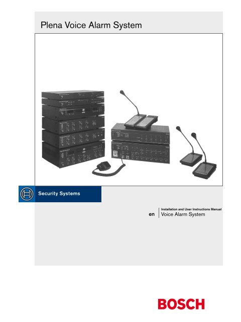
<strong>Plena</strong> <strong>Voice</strong> <strong>Alarm</strong> <strong>System</strong>enInstallation and User Instructions Manual<strong>Voice</strong> <strong>Alarm</strong> <strong>System</strong>
<strong>Plena</strong> <strong>Voice</strong> <strong>Alarm</strong> <strong>System</strong> | Installation and User Instructions | Important Safeguards en | 3Important SafeguardsPrior to installing or operating this product, always readthe Important Safety Instructions which are available asa separate document (9922 141 7014x).<strong>Bosch</strong> Security <strong>System</strong>s | 2004-06 | 9922 141 10371en
<strong>Plena</strong> <strong>Voice</strong> <strong>Alarm</strong> <strong>System</strong> | Installation and User Instructions | Table of Contents en | 75.3.1 Monitor ...............................................................................................................................................................475.3.2 APR mode ..........................................................................................................................................................475.3.3 Supervision .........................................................................................................................................................475.3.4 2-channel operation ...........................................................................................................................................505.4 Mic/line input with VOX functionality configuration ........................................................................................505.4.1 VOX input source selector ...............................................................................................................................505.4.2 VOX configuration DIP switch .......................................................................................................................505.4.3 VOX volume control ........................................................................................................................................515.4.4 Vox ......................................................................................................................................................................515.4.5 Speech filter ........................................................................................................................................................515.4.6 Phantom power ..................................................................................................................................................515.5 Call station configuration DIP switch ...................................................................................................................515.5.1 Call station ID ....................................................................................................................................................515.5.2 Sensitivity ............................................................................................................................................................525.5.3 Speech filter ........................................................................................................................................................525.5.4 Termination ........................................................................................................................................................525.6 Router .......................................................................................................................................................................525.6.1 ID rotary switch .................................................................................................................................................525.6.2 Termination switch ............................................................................................................................................526. Operation ........................................................................................................................................................................536.1 Switching ON ..........................................................................................................................................................536.2 Switching OFF .........................................................................................................................................................536.3 Calibrating the controller .......................................................................................................................................536.4 Background music ..................................................................................................................................................536.4.1 Selecting a BGM source ....................................................................................................................................536.4.2 Selecting BGM zones ........................................................................................................................................536.4.3 Adjusting BGM volume ....................................................................................................................................546.4.4 Adjusting BGM tone .........................................................................................................................................546.5 Business calls ...........................................................................................................................................................546.5.1 Selecting zones ...................................................................................................................................................546.5.2 Making a business announcement ...................................................................................................................556.6 Emergency state ......................................................................................................................................................556.6.1 Entering the emergency state ...........................................................................................................................556.6.2 Stopping the beeper ..........................................................................................................................................556.6.3 Exiting the emergency state .............................................................................................................................566.7 Emergency calls ......................................................................................................................................................566.7.1 Selecting zones ...................................................................................................................................................566.7.2 Making an emergency call ................................................................................................................................566.8 Alert messages .........................................................................................................................................................576.8.1 Starting the alert message .................................................................................................................................576.9 <strong>Alarm</strong> messages .......................................................................................................................................................576.9.1 Starting the alarm message ...............................................................................................................................577. Fault Handling ...............................................................................................................................................................597.1 Introduction .............................................................................................................................................................597.2 Fault indicators ........................................................................................................................................................597.2.1 Line fault indicators ...........................................................................................................................................597.2.2 <strong>System</strong> fault indicators ......................................................................................................................................597.2.3 Supervision disabled ..........................................................................................................................................59<strong>Bosch</strong> Security <strong>System</strong>s | 2004-06 | 9922 141 10371en
<strong>Plena</strong> <strong>Voice</strong> <strong>Alarm</strong> <strong>System</strong> | Installation and User Instructions | Table of Contents en | 87.2.4 Indicator test .......................................................................................................................................................597.3 Troubleshooting a fault ..........................................................................................................................................607.4 <strong>System</strong> faults ............................................................................................................................................................618. Technical Data ...............................................................................................................................................................638.1 Call Station LBB1956/00 .......................................................................................................................................638.1.1 Electrical .............................................................................................................................................................638.1.2 Performance .......................................................................................................................................................638.1.3 Interconnection ..................................................................................................................................................638.1.4 Environmental conditions .................................................................................................................................638.1.5 General ...............................................................................................................................................................638.2 <strong>Voice</strong> <strong>Alarm</strong> Controller LBB1990/00 ..................................................................................................................638.2.1 Electrical .............................................................................................................................................................638.2.2 Message manager ..............................................................................................................................................648.2.3 Internal booster ..................................................................................................................................................648.2.4 Interconnection ..................................................................................................................................................648.2.5 Loudspeaker outputs .........................................................................................................................................648.2.6 Overrides ............................................................................................................................................................648.2.7 Trigger outputs ...................................................................................................................................................648.2.8 Trigger inputs/24 V DC out .............................................................................................................................658.2.9 VOX input .........................................................................................................................................................658.2.10 BGM ....................................................................................................................................................................658.2.11 Line out ...............................................................................................................................................................658.2.12 External booster .................................................................................................................................................658.2.13 Environmental conditions .................................................................................................................................658.2.14 General ...............................................................................................................................................................658.3 Router LBB1992/00 ................................................................................................................................................659. Glossary ............................................................................................................................................................................67<strong>Bosch</strong> Security <strong>System</strong>s | 2004-06 | 9922 141 10371en
<strong>Plena</strong> <strong>Voice</strong> <strong>Alarm</strong> <strong>System</strong> | Installation and User Instructions | Introduction en | 91 Introduction1.1 PurposeThe purpose of the Installation and User InstructionsManual is to provide information required to install,configure, operate and maintain a <strong>Plena</strong> <strong>Voice</strong> <strong>Alarm</strong><strong>System</strong>. A <strong>Plena</strong> voice alarm controller (systemcontroller) forms the heart of a <strong>Plena</strong> <strong>Voice</strong> <strong>Alarm</strong><strong>System</strong>. Unlike a basic system (see also the Basic <strong>System</strong>Manual, 9922 141 10361), a <strong>Plena</strong> <strong>Voice</strong> <strong>Alarm</strong> <strong>System</strong>may be configured, using all available units of the <strong>Plena</strong>product line, including one or more routers, call stationsand call station extensions, to simultaneously serve andmanage up to 60 loudspeaker zones.A <strong>Plena</strong> <strong>Voice</strong> <strong>Alarm</strong> <strong>System</strong> can be extensivelyconfigured from a PC, running the ConfigurationSoftware. How to use this software is described in theConfiguration Software Manual (9922 141 10381). Inthis manual the <strong>Plena</strong> <strong>Voice</strong> <strong>Alarm</strong> <strong>System</strong> is furtherreferred to as “system”.1.2 Digital documentThis Installation and User Instructions Manual is alsoavailable as a digital document in the Adobe PortableDocument Format (PDF). All references to pages,figures, tables, etc. in this digital document containhyperlinks, to quickly consult the referenced location.1.3 Intended audienceThis Installation and User Instructions Manual isintended for installers and users of a <strong>Plena</strong> <strong>Voice</strong> <strong>Alarm</strong><strong>System</strong>.1.4 Related documentationThe following related documents are available:• Basic <strong>System</strong> Manual (9922 144 10361).• Configuration Software Manual(9922 144 10381).1.5 AlertsIn this manual, four types of alerts are used. The alerttype is closely related to the effect that may be causedwhen it is not observed. These alerts - from least severeeffect to most severe effect - are:• NoteAlert containing additional information. Usually, notobserving a note alert does not result in damage tothe equipment or personal injuries.• CautionThe equipment can be damaged if the alert is notbeing observed.• WarningPersons can be (severely) injured or the equipmentcan be seriously damaged if the alert is not beingobserved.• DangerNot observing the alert can result in death.In this manual, the following indicators are used foralerts:NoteGeneral sign for notes.NoteConsult the indicated source of information.Caution, Warning, DangerGeneral sign for cautions, warnings anddangers.Caution, Warning, DangerRisk of electric shock.Caution, Warning, DangerRisk of electrostatic discharges.<strong>Bosch</strong> Security <strong>System</strong>s | 2004-06 | 9922 141 10371en
<strong>Plena</strong> <strong>Voice</strong> <strong>Alarm</strong> <strong>System</strong> | Installation and User Instructions | Introduction en | 101.6 Conversion tablesIn this manual, SI units are used to express lengths,masses, temperatures etcetera. Metric units can beconverted to non-metric units using the informationprovided below.table 1.1: Conversion of length units1 in = 25.4 mm 1 mm = 0.03937 in1 in = 2.54 cm 1 cm = 0.3937 in1 ft = 0.3048 m 1 m = 3.281 ft1 mi = 1.609 km 1 km = 0.622 mitable 1.2: Conversion of mass units1 lb = 0.4536 kg 1 kg = 2,2046 lbtable 1.3: Conversion of pressure units1 psi = 68.95 hPa 1 hPa = 0.0145 psiNote1 hPa = 1 mbar.table 1.4: Conversion of temperature units95°F = -- ⋅ °C + 32°C = -- ⋅ ( °F – 32)59<strong>Bosch</strong> Security <strong>System</strong>s | 2004-06 | 9922 141 10371en
<strong>Plena</strong> <strong>Voice</strong> <strong>Alarm</strong> <strong>System</strong> | Installation and User Instructions | Application examples en | 112 Application examples2.1 IntroductionIn a <strong>Plena</strong> <strong>Voice</strong> <strong>Alarm</strong> <strong>System</strong>, any of the various unitsoffered by the <strong>Plena</strong> product family, can be combinedtogether, in order to satisfy with any of your specificconfiguration requirements. This chapter provides anumber of examples, each describing a specific systemconfiguration. You can use these examples and quicklyadapt them to meet your own configurationrequirements.2.1.1 <strong>Plena</strong>The <strong>Plena</strong> <strong>Voice</strong> <strong>Alarm</strong> <strong>System</strong> is part of the <strong>Plena</strong>product range. <strong>Plena</strong> provides public address solutionsfor places where people gather to work, worship, tradeor simply enjoy themselves. It is a family of systemelements that are combined to create public addresssystems tailored for virtually any application. The rangeincludes mixer, pre-, system- and booster amplifiers, asource unit, digital message manager, feedbacksuppressor, call stations, an ‘All-in-One’ system and avoice alarm system. Each element is designed tocomplement all others thanks to matched acoustical,electrical and mechanical specifications.2.1.2 Application areasTypically, the <strong>Plena</strong> <strong>Voice</strong> <strong>Alarm</strong> <strong>System</strong> is used tocreate small systems that must comply witih emergencyand evacuation standards, medium-sized systems inwhich one call channel is enough and large systems thatconsists of many small zones.The application areas of a <strong>Plena</strong> <strong>Voice</strong> <strong>Alarm</strong> <strong>System</strong>include:• Schools, see section 2.2.• Swimming pools, see section 2.3.• Shopping malls, see section 2.4.• Hotels, see section 2.5.Other areas include: factories, high-rise buildings, officebuildings, recreational facilities and small airports.2.2 Application: School2.2.1 IntroductionSchools are typical example of applications with a largenumber of zones each with a relatively low outputpower requirement per zone. The main priorities arespeech intelligibility and compliance with IEC60849standard (or equivalent).2.2.2 RequirementsIn addition to mandatory voice alarm functionality forevacuating staff and students, Econtroller systems forschools should also include chime tones for notifyingthe start/finish of lessons, plus public addressfunctionality for individually calling classrooms orpublic area. BGM is not essential. Since a classroom hasa low ambient noise level, one loudspeaker is usuallysufficient, keeping the total power requirementrelatively low. Outside areas such as playgrounds andsports fields will require weatherproof hornloudspeakers.table 2.1: Summary of requirementsRequirements30 zones (typically 20 to 60 zones).Speech intelligibility is the main priority.Low power requirement (one loudspeaker) perclassroom.Fireman’s panel by main entrance.Call station in main office.Additional public address functions such as chimetones desirable.BGM in recreation areas is optional.2.2.3 SolutionThe <strong>Plena</strong> voice alarm controller handles messagerouting to 6 zones, the remaining 24 zones require fouradditional 6-zone routers. The office is equipped with acall station plus keypads for individually addressingzones, while a fireman’s panel (with overall priority) isbuilt in by the main entrance.2.2.4 Power requirementsThe voice alarm controller features a built-in 240 Wbooster amplifier, making it possible to drive up to 40loudspeakers with a power handling capacity of 6 Weach. This is sufficient for a medium-sized high schoolwith 24 classrooms, four toilets/changing rooms, a staff<strong>Bosch</strong> Security <strong>System</strong>s | 2004-06 | 9922 141 10371en
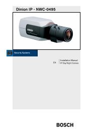
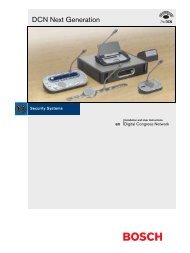
<strong>Plena</strong> <strong>Voice</strong> <strong>Alarm</strong> <strong>System</strong> | Installation and User Instructions | Application examples en | 12meeting room and two offices, each requiring a singleloudspeaker. The canteen, assembly hall, playing fieldsand corridors typically require more loudspeakers perzone. An additional <strong>Plena</strong> booster amplifier is used as aspare amplifier.table 2.2: Power requirements per zoneZone Description Power1-22 Classrooms 22x6W cabinet23 Toilets 4x6W ceiling24 Staff meeting room 1x6W cabinet25-26 Offices 2x6W cabinet27 Corridors 4x6W projector28 Assembly hall 2x6W ceiling29 Lunch canteen 2x6W ceiling30 Playing fields 1x10W hornTotal232W2.2.5 <strong>System</strong> configurationThe <strong>Plena</strong> units, needed to build the application, arelisted in table 2.3. The interconnections are shown infigure 2.1.table 2.3: Used <strong>Plena</strong> unitsUnit Description NumberLBB1990/00 <strong>Voice</strong> alarm controller 1xLBB1992/00 Router 4xLBB1996/00 Remote control panel 1xLBB1997/00 RCP extension 4xLBB1956/00 Call station 1xLBB1957/00 CS extension keypad 4xLBB1935/00 240W booster 1x<strong>Bosch</strong> Security <strong>System</strong>s | 2004-06 | 9922 141 10371en
<strong>Plena</strong> <strong>Voice</strong> <strong>Alarm</strong> <strong>System</strong> | Installation and User Instructions | Application examples en | 13zones 25-30zones 19-24zones 13-18zones 7-12zones 1-6240 W boosterrouterscall station keypadscontrollercall stationremote control panelfigure 2.1: <strong>Plena</strong> <strong>Voice</strong> <strong>Alarm</strong> <strong>System</strong>, application example: schoolremote control panel extensions<strong>Bosch</strong> Security <strong>System</strong>s | 2004-06 | 9922 141 10371en
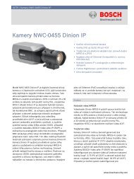
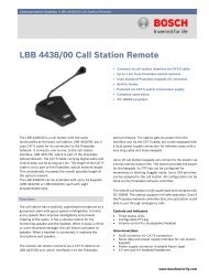
<strong>Plena</strong> <strong>Voice</strong> <strong>Alarm</strong> <strong>System</strong> | Installation and User Instructions | Application examples en | 142.3 Application: Swimming pool2.3.1 IntroductionSwimming pools and other indoor sports andrecreational facilities are typical examples of smallerapplications with few zones. The main priorities areexcellent speech intelligibility and compliance withIEC60849 standard (and its national equivalents),although music in different areas is optional.2.3.2 RequirementsAn Econtroller system for a swimming pool requiresvoice alarm functionality with public addressfunctionality for regular announcements andbackground music (optional). To ensure that all visitorsin the relatively noisy pool area hear emergencymessages, the power output for that zone is relativelyhigh. Other areas, such as the changing rooms andoffices, have lower power requirements.table 2.4: Summary of requirementsRequirements5 zones (typically up to 6 zones)Speech intelligibility is the main priorityHigh power requirement in the noisy pool areaFireman’s panel by fire exitCall station in office/receptionAdditional public address functions forannouncementsBGM2.3.3 SolutionThe <strong>Plena</strong> voice alarm controller handles routing to upto 6 zones, so no additional routers are required. Theoffice/reception is equipped with a call station pluskeypad for individually addressing zones, while afireman’s panel (with overall priority) is built in by theemergency exit. The <strong>Plena</strong> voice alarm systemis a two-channel system, so BGM can still be providedin zones not receiving a call.2.3.4 Power requirementsThe voice alarm controller has a built-in 240 W boosteramplifier, making it possible to drive up to 40loudspeakers with a power handling capacity of 6 Weach. The pool area requires highpower music hornloudspeakers qualified for use in a high humidityatmosphere. The snack bar uses cabinet loudspeakersfor music reproduction. The zones are defined asindicated in the table. An additional <strong>Plena</strong> boosteramplifier is used for two-channel operation and as aspare amplifier.table 2.5: Power requirements per zoneZone Description Power1 Indoor pool area 5x30W horn2 Children’s pool area 2x10W horn3 Changing rooms 4x6W ceiling4 Snack bar 4x6W cabinet5 Office 2x6W cabinetTotal230W2.3.5 <strong>System</strong> configurationThe <strong>Plena</strong> units, needed to build the application, arelisted in table 2.6. The interconnections are shown infigure 2.2.table 2.6: Used <strong>Plena</strong> unitsUnit Description NumberLBB1990/00 <strong>Voice</strong> alarm controller 1xLBB1996/00 Remote control panel 1xLBB1956/00 Call station 1xLBB1957/00 CS extension keypad 1xLBB1935/00 240W booster 1xLBB1961/00 BGM source 1x<strong>Bosch</strong> Security <strong>System</strong>s | 2004-06 | 9922 141 10371en
<strong>Plena</strong> <strong>Voice</strong> <strong>Alarm</strong> <strong>System</strong> | Installation and User Instructions | Application examples en | 15zones 1-5240 W boosterBGM sourcecall station keypadcall stationcontrollerremote control panelfigure 2.2: <strong>Plena</strong> <strong>Voice</strong> <strong>Alarm</strong> <strong>System</strong>, application example: swimming pool<strong>Bosch</strong> Security <strong>System</strong>s | 2004-06 | 9922 141 10371en
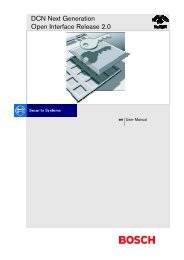
<strong>Plena</strong> <strong>Voice</strong> <strong>Alarm</strong> <strong>System</strong> | Installation and User Instructions | Application examples en | 162.4 Application: Shopping mall2.4.1 IntroductionShopping malls are typical example of applications witha large number of zones with varying output powerrequirements per zone. The priorities are speechintelligibility and compliance with IEC60849 standard(and its national equivalents).2.4.2 RequirementsIn addition to mandatory voice alarm functionality forevacuating the public and shop personnel, anEcontroller system for shopping centers can have BGMfor the public areas. It should be possible to individuallycall each shop or store. During emergency messages, thevolume override of each individual shop is engaged.Additional public address functionality for makinggeneral public announcements is an optionalrequirement.table 2.7: Summary of requirementsRequirements54 zones (typically up to 60 zones)Speech intelligibility is the main priorityVariable power requirement per zoneCall station in security control roomAdditional public address functionality(nonemergency)BGM in public areasBGM music with local override in shops2.4.3 SolutionA <strong>Plena</strong> voice alarm controller handles routing to 6zones, the remaining 48 zones require eight 6-zonerouters. The security control room is equipped with aremote control panel and call station plus keypads forindividually addressing zones and BGM for the publicareas, while the controller unit and routers are locatedin a fire-resistant cabinet or basement. Fireman’s panel(with overall priority) is built in close to the mainentrance or emergency exit (subject to relevant localregulations). The <strong>Plena</strong> voice alarm system is a twochannelsystem, so BGM can still be provided in zonesnot receiving a call.2.4.4 Power requirementsEach zone will have varying power requirements,ranging from small shops with a single loudspeaker todepartment stores with several floors and moreloudspeakers. Parking garages and open-air walkwayswill require weatherproof sound projectors or hornloudspeakers. To facilitate phased evacuation fromdifferent levels of the shopping center, public areas aredivided into zones. Additional <strong>Plena</strong> booster amplifiersare incorporated to provide additional power, twochanneloperation and for use as a spare amplifier.table 2.8: Power requirements per zoneZone Description Power1-30 30 small shops 30x6W cab/ceil31-36 6 small shops 12x6W 2/store37-42 6 medium stores 24x6W ceiling43-46 Large store, 4 levels 16x6W ceiling47 Control room 1x6W cabinet48 Offices 4x6W cabinet49 Walkways gnd floor 4x6W projector50 Gallery 1st floor 10x6W ceiling51 Gallery 2nd floor 10x6W ceiling52 Main public square 4x18W horn53 Parking level 1 6x10W horn54 Parking level 2 6x10W hornTotal858W2.4.5 <strong>System</strong> configurationThe <strong>Plena</strong> units, needed to build the application, arelisted in table 2.9. The interconnections are shown infigure 2.3.table 2.9: Used <strong>Plena</strong> unitsUnit Description NumberLBB1990/00 <strong>Voice</strong> alarm controller 1xLBB1992/00 Router 8xLBB1996/00 Remote control panel 1xLBB1997/00 RCP extension 8xLBB1998/00 RCP kit 1xLBB1999/00 RCP extension kit 8xLBB1956/00 Call station 1xLBB1957/00 CS extension keypad 5xLBB1935/00 240W booster 3xLBB1938/00 480 booster 2xLBB1961/00 BGM source 1x<strong>Bosch</strong> Security <strong>System</strong>s | 2004-06 | 9922 141 10371en
<strong>Plena</strong> <strong>Voice</strong> <strong>Alarm</strong> <strong>System</strong> | Installation and User Instructions | Application examples en | 17zones 49-54zones 43-48zones 37-42zones 31-36480 W boosterszones 7-12zones 13-18zones 25-30zones 19-24zones 1-6240 W boosters240 W boosterroutersBGM sourcecontrollerremote control panelcall station keypadscall stationfireman's panelremote control panel extensionsfigure 2.3: <strong>Plena</strong> <strong>Voice</strong> <strong>Alarm</strong> <strong>System</strong>, application example: shopping mall2.4.6 Uplink to PreasideoIn large voice alarm system configurations, as in bigshopping malls, it is possible to have a <strong>Plena</strong> systemintegrated with a Preasideo system. An uplink from a<strong>Plena</strong> system to a Preasideo system can be establishedby interconnecting a Preasideo audio output with the<strong>Plena</strong> mic/line input with VOX functionality.Emergency calls issued from the Preasideo system, arethen broadcast on the <strong>Plena</strong> system. For this purpose the<strong>Plena</strong> mic/line input with VOX functionality should beassigned the highest possible priority level (14).NoteRefer to the Configuration Software Manual(9922 141 10381) for details about configuringpriority levels.<strong>Bosch</strong> Security <strong>System</strong>s | 2004-06 | 9922 141 10371en
<strong>Plena</strong> <strong>Voice</strong> <strong>Alarm</strong> <strong>System</strong> | Installation and User Instructions | Application examples en | 182.5 Application: Hotel2.5.1 IntroductionSmaller hotels are typical examples of applications withrelatively few zones, each with a medium to high outputpower requirement. The priorities are speechintelligibility and compliance with IEC60849 standard.2.5.2 RequirementsIn addition to mandatory voice alarm functionality forevacuating guests and staff, an Econtroller system for ahotel should also include BGM in the restaurant, barand lobby, plus public address functionality for generalpaging. To ensure that all guests hear an emergencymessage, the power output per zone is relatively high.Outside areas such as car parking garages, requireweatherproof horn loudspeakers.table 2.10: Summary of requirementsRequirements12 zones (typically 10 to 20 zones in small hotels)Speech intelligibility is the main priorityHigh power requirement (multiple loudspeakers)per floorFireman’s panel by fire exitCall stations in reception and officeAdditional public address functions for pagingguestsBGM in lobby and restaurant2.5.3 SolutionA <strong>Plena</strong> voice alarm controller handles routing to up to6 zones, the additional 6 zones require a router. Boththe reception and office are equipped with call stationsplus keypads for individually addressing zones, while afireman’s panel (with overall priority) is built in by theemergency exit. The <strong>Plena</strong> <strong>Voice</strong> <strong>Alarm</strong> <strong>System</strong> is atwo-channel system, so BGM can still be provided inzones not receiving a call.2.5.4 Power requirementsThe system controller features a built-in 240 W boosteramplifier, able to drive up to 40 loudspeakers (6 W).Additional <strong>Plena</strong> booster amplifiers are incorporated toprovide additional power, two-channel operation andspare amplification. To facilitate phased evacuationfrom different floors of the hotel, guest areas are dividedinto separate zones, each fitted with 13 ceilingloudspeakers in the corridors. The bar uses cabinetloudspeakers, while the parking garage usesweatherproof horn loudspeakers. The zones are definedas shown in the table opposite.table 2.11: Power requirements per zoneZone Description Power1 Bar 3x6W cabinet2 Restaurant 6x6W ceiling3 Lobby 2x6W ceiling4 Office 1x6W cabinet5 Kitchens 2x6W cabinet6 Parking garage 3x10W horn7-12 Floors 1 to 6 78x6W ceilingTotal582W2.5.5 <strong>System</strong> configurationThe <strong>Plena</strong> units, needed to build the application, arelisted in table 2.12. The interconnections are shown infigure 2.4.table 2.12: Used <strong>Plena</strong> unitsUnit Description NumberLBB1990/00 <strong>Voice</strong> alarm controller 1xLBB1992/00 Router 1xLBB1996/00 Remote control panel 1xLBB1997/00 RCP extension 1xLBB1956/00 Call station 2xLBB1957/00 CS extension keypad 3xLBB1938/00 480 booster 2xLBB1935/00 240W booster 1xLBB1961/00 BGM source 1x<strong>Bosch</strong> Security <strong>System</strong>s | 2004-06 | 9922 141 10371en
<strong>Plena</strong> <strong>Voice</strong> <strong>Alarm</strong> <strong>System</strong> | Installation and User Instructions | Application examples en | 19480 W boosterzones 1-6zones 7-12240 W boosterrouterBGM sourcecall station keypadcontrollercall station keypadscall stationcall stationremote control panelremote control panel extensionsfigure 2.4: <strong>Plena</strong> <strong>Voice</strong> <strong>Alarm</strong> <strong>System</strong>, application example: hotel<strong>Bosch</strong> Security <strong>System</strong>s | 2004-06 | 9922 141 10371en
<strong>Plena</strong> <strong>Voice</strong> <strong>Alarm</strong> <strong>System</strong> | Installation and User Instructions | Chapter 2 | Configuration en | 20<strong>Bosch</strong> Security <strong>System</strong>s | 2004-06 | 9922 141 10371en
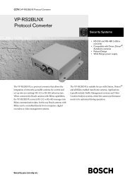
<strong>Plena</strong> <strong>Voice</strong> <strong>Alarm</strong> <strong>System</strong> | Installation and User Instructions | <strong>System</strong> units en | 213 <strong>System</strong> units3.1 IntroductionThe <strong>Plena</strong> product family comprises various units thatcan be used to configure a <strong>Plena</strong> <strong>Voice</strong> <strong>Alarm</strong> <strong>System</strong>,to meet your specific configuration requirements. Thischapter first describes the functionality of each of the<strong>Plena</strong> units and explains their usage. Further on in thischapter, for each of the units, an overview is provided ofthe connectors, controls and indicators.NoteRefer to the Configuration Software Manual(9922 141 10381) to configure the triggerinputs.To connect the trigger inputs, refer to section 4.7.LBB1990/00<strong>Voice</strong> <strong>Alarm</strong> Controller3.2 <strong>Voice</strong> alarm controllerThe voice alarm controller (LBB1990/00) is the heart ofthe <strong>Plena</strong> <strong>Voice</strong> <strong>Alarm</strong> <strong>System</strong>. The voice alarmcontroller (further referred to as “controller”) centrallymanages and distributes emergency calls, business callsand background music (BMG). A single controller isable to serve and manage 6 loudspeaker zones. If morezones are to be served, extra routers can be connected(see section 3.3). Like this, up to a maximum of 60 zonescan be served. The controller is equipped with aninternal booster (see section 3.2.4) and an integratedmessage manager (see section 3.2.5). All <strong>Plena</strong> units tobe used, can be connected to the central controller.Trigger input/24V DC outEmergency1 2 3 4 5 6Business1 2 3 4 5 61 2 3 4 5 624VDC outVOXSwitch24VDC out10k10k1 2 3 4 5 6VOX Switchfigure 3.2: Trigger inputsfigure 3.1: <strong>Voice</strong> alarm controller (LBB1990/00)3.2.1 Trigger inputsThe rearside of the controller provides a terminal blockfor the connection of 6 EMG and 6 business triggerinputs. The EMG trigger inputs have a higher priority inbeing served, than the business trigger inputs. Thetrigger inputs can be used to signal events to thecontroller. To each trigger input, a prerecorded messagecan be assigned and broadcast to one or more zones orzonegroups.3.2.2 Loudspeaker zonesThe controller can serve 6 loudspeaker zones. Incompliance with IEC60849, the supply to each zone isredundantly designed. For this purpose, on the rearsideof the controller, there are two zone output terminalblocks (A and B). To connect the zone outputs, refer tosection 4.8.<strong>Bosch</strong> Security <strong>System</strong>s | 2004-06 | 9922 141 10371en
<strong>Plena</strong> <strong>Voice</strong> <strong>Alarm</strong> <strong>System</strong> | Installation and User Instructions | <strong>System</strong> units en | 22LBB1990/00<strong>Voice</strong> <strong>Alarm</strong> ControllerZ1A100V0100VZ20100VZ30100VZ40100VZ50100VZ60Ext 100VBoosterIn 0DC In 24V100VZ10100VZ20100VZ30100VZ40100VZ5 TR0100VZ60100VInt70V BoosterOut0Call outfigure 3.3: Zone output terminal blocks3.2.3 Hand-held EMG microphoneThe controller is equipped with a hand-held EMGmicrophone, which can be used to make emergencycalls. To be able to make business calls, one or more callstations (LBB1956/00) must be connected to thecontroller (see section 3.4).figure 3.4: Hand-held EMG microphoneB100VBGM. Optionally, a spare external booster can beconnected (see also section 3.3.2). The externalbooster will only be activated when the internalbooster fails.• In 2-channel mode, an external booster (see alsosection 3.3.2) must be connected to the controller.The internal booster of the controller amplifies theBGM and the external booster amplifies the calls. In2-channel mode, calls do not interrupt the BGM.If one or more routers (see also section 3.3) areconnected to the controller, to each router, twoadditional external boosters can be connected. See alsosection 3.3.2.3.2.5 Internal message managerThe controller has an internal message manager, whichmanages and distributes all prerecorded messages andchimes. Up to 255 prerecorded messages can be storedas wave files (.wav) in an EEPROM, and can be usedboth in emergency and in business calls. Wave files canbe created and uploaded to the message manager, froma PC running the Configuration Software.NoteRefer to the Configuration Software Manual(9922 141 10381) for details about creatingprerecorded messages for the messagemanager.3.2.6 SupervisionThe controller integrates all required supervisionfeatures, in accordance with the international standardIEC60849 applicable for emergency systems. Variousfunctions of the controller are supervised. Supervision isswitched ON by default. Supervision can be switchedOFF by setting the supervision DIP switch in the OFFposition (see section 5.3). If supervision is enabled, anyfailing function will cause the controller to enter thefault state and the corresponding fault indicator isturned ON (see also section 7.2).3.2.4 Internal boosterThe controller is equipped with a 240 W internalbooster, which can be used in 1-channel or 2-channelmode:• In 1-channel mode, the internal booster amplifies callsand BGM. In 1-channel mode, calls will interrupt the<strong>Bosch</strong> Security <strong>System</strong>s | 2004-06 | 9922 141 10371en
<strong>Plena</strong> <strong>Voice</strong> <strong>Alarm</strong> <strong>System</strong> | Installation and User Instructions | <strong>System</strong> units en | 23LBB1990/00<strong>Voice</strong> <strong>Alarm</strong> Controller3.3.1 Trigger inputsIn addition to the trigger inputs supplied by thecontroller, each router adds 6 extra EMG and businesstrigger inputs to the <strong>Plena</strong> <strong>Voice</strong> <strong>Alarm</strong> <strong>System</strong>.NoteRefer to the Configuration Software Manual(9922 141 10381) to configure the triggerinputs.Fault IndicatorsProcessor resetNetworkCall/EMGMusic/SpareGround shortInputMainsBatteryMessageEMG micRCPRouterADisabledBZone1Zone2Zone3Zone4Zone5Zone6To connect the trigger inputs, refer to section 4.7.LBB1992/00RouterTrigger InputEmergency1 2 3 4 5 6figure 3.5: Fault indicator LEDsBusiness1 2 3 4 5 610k10k3.3 RouterA single controller can serve and manage 6 loudspeakerzones. To extend the number of zones, one or morerouters (LBB1992/00) can be connected. In total, 6 extrarouters can be connected to a controller, each adding 6extra loudspeaker zones. As a consequence, in itsmaximum configuration, a <strong>Plena</strong> <strong>Voice</strong> <strong>Alarm</strong> <strong>System</strong>can simultaneously serve and manage up to 60loudspeaker zones. If the power supplied by thecontroller is not sufficient, two additional externalboosters can be connected to each router (see alsosection 3.3.2).figure 3.6: Router (LBB1992/00)figure 3.7: Trigger inputs1 2 3 4 5 61 2 3 4 5 63.3.2 External boostersA router does not have an internal booster. If the power,supplied by the controller, is not sufficient, twoadditional external boosters (1 and 2) can be connectedto a router. Multiple boosters can be connected toamplify calls and BGM or just to serve as backupboosters. The function of a booster depends on themode for which the controller is configured:• In 1-channel mode, external booster 1 is additionalto the controller’s internal booster (see section 3.2.4)to amplify calls and BGM.• In 2-channel mode, external booster 2 is additionalto the controller’s external booster (see section 3.2.4)to amplify calls.To connect external boosters, see section 4.15.3.2.<strong>Bosch</strong> Security <strong>System</strong>s | 2004-06 | 9922 141 10371en
<strong>Plena</strong> <strong>Voice</strong> <strong>Alarm</strong> <strong>System</strong> | Installation and User Instructions | <strong>System</strong> units en | 24LBB1992/00RouterBooster 1Booster 21 Channel 2 ChannelBGM/Call BGM/SpareN.C./Spare CallA Z1 Z2 Z3 Z4 Z5 Z6 Booster 1 in Call out100V 0 100V 0 100V 0 100V 0 100V 0 100V 0 100V 70V 0 100VA call station has 6 Zone Select buttons, one All Callbutton and a PTT button. The Zone Select buttons canbe configured, for selecting zones or zone groups withinthe system. The PTT (Push To Talk) button can beassigned a pre- and/or a post-chime. Each call stationcan be assigned a priority level between 1 - 6. If a <strong>Plena</strong><strong>Voice</strong> <strong>Alarm</strong> <strong>System</strong> serves more than 6 zones, it ispossible to connect one or more call station extensionkeypads to a call station (see section 3.4.1).100V 0 100V 0 100V 0 100V 0 100V 0 100V 0 100V 0 +24V-B Z1 Z2 Z3 Z4 Z5 Z6 Booster 2 in DC InNoteRefer to the Configuration Software Manual(9922 141 10381) for details about configuringa call station.figure 3.8: External boosters3.4 Call stationIn total 8 call stations (LBB1956/00) can be connectedto the controller for making business calls. The rearsideof the controller provides two RJ45 connectors for theconnection of the call stations. To connect call stations,refer to section 4.14.In accordance with IEC60849, the controller disables allcall stations during an emergency call (see section 6.7)or an active emergency trigger (see section 4.7.1). A callstation is not supervised.3.4.1 Extension keypadEach router (see section 3.3) that is connected to acontroller, adds 6 extra zones. To be able to select allthese extra zones from a call station, it is possible toconnect at maximum 8 extension keypads (LBB1957/00) to a call station. Each call station extension keypadprovides 7 extra Zone select buttons, for selecting zonesor zone groups within the system. A call stationautomatically detects how many keypads are connected.To connect extension keypads, see section 4.14.1.figure 3.9: <strong>Plena</strong> call station (LBB1956/00)figure 3.10: Extension keypad (LBB1957/00)<strong>Bosch</strong> Security <strong>System</strong>s | 2004-06 | 9922 141 10371en
<strong>Plena</strong> <strong>Voice</strong> <strong>Alarm</strong> <strong>System</strong> | Installation and User Instructions | <strong>System</strong> units en | 25The buttons of a call station extension keypad can beconfigured using the Configuration Software.NoteRefer to the Configuration Software Manual(9922 141 10381) for details about configuringa call station keypad.3.5 Controls, connections andindicators3.5.1 <strong>Voice</strong> alarm controllerSee figure 3.11 for an overview of the controls,connections and indicators on the voice alarm controller(LBB1990/00):1 Power LED/VU Meter - A combined powerindicator and VU meter. The green power LED is litif the voice alarm controller is connected to themains or back-up power and switched on. The VUmeter indicates the master VU level: 0 dB (red), - 6dB, -20 dB (yellow).2 Fault indicators - Twelve yellow system faultLEDs (Processor reset, Network, Call/EMG, Music/Spare,Ground short, Input, Mains, Battery, Message, EMG mic,RCP and Router) and twelve yellow loudspeaker linefault LEDs. Fault indication is only possible ifsupervision is enabled (see section 5.7). Ifsupervision is disabled, the yellow Disabled LED is lit.3 Fault state keys - Two keys to acknowledge (Ack)and reset (Reset) the fault state (see section 5.7).4 Emergency state keys - Two keys toacknowledge (Ack) and reset (Reset) the emergencystate (see section 5.6).5 Emergency call zone selectors - Six keys toselect the zones to which the emergency call must bedistributed (see section 5.6). Each button has a greenand a red LED. The six red LEDs indicate the zonesthat are selected for the emergency call. The sixgreen LEDs indicate the zones in which a businesscall is running (see section 5.6).6 BGM zone selectors - Six keys to select the zonesto which the BGM is distributed (see section 5.4).Each button has a green LED and a rotary knob.The six green LEDs indicate the zones to whichBGM is distributed. The six rotary knobs are localvolume controls that can be used to adjust thevolume of the BGM in each zone.7 BGM master volume control - A rotary knob toset the master volume of the BGM (see section 5.4).8 BGM source selector - A button to select theBGM source (CD/Tuner or Aux). The selected sourceis indicated with a green LED (see section 5.4).9 BGM tone controls - Two rotary knobs to controlthe high and low frequencies of the BGM (seesection 5.6).10 All call button- A button to select all zones. Thisbutton is only available in the emergency state (seesection 5.6).11 Indicator test button - A button to test all LEDson the front panel of the voice alarm controller. AllLEDs are lit as long as the button is pressed (seesection 5.7).12 Emergency button - A push button to put thesystem in the emergency state (see section 5.6).13 Alert message button - A button to select thealert message. This button is only available in theemergency state (see section 5.6).14 <strong>Alarm</strong> message button - A button to select thedefault alarm message. This button is only availablein the emergency state (see section 5.6).15 Microphone socket - A socket to connect thehand-held emergency microphone (see section 3.6).16 Bracket - A bracket for the hand-held emergencymicrophone that is supplied with the voice alarmcontroller.17 Monitoring speaker - Built-in monitoringspeaker.18 Zone outputs - Six zone outputs to connectloudspeakers to the voice alarm controller. Eachzone output consists of two loudspeaker line outputs(see section 3.10).19 Override outputs - Six volume override outputs tooverride local volume controls in each zone (seesection 3.11).20 Status outputs - Three status outputs to send thestatus of the <strong>Plena</strong> <strong>Voice</strong> <strong>Alarm</strong> <strong>System</strong> to third partyequipment (see section 3.14).21 Trigger inputs/24 V DC input - Twelve triggerinputs to receive signals from third party equipmentand one 24 V(DC) output. Except for the VOX switchinput and the 24V DC out output, these must beconfigured with the configuration software and aretherefore not used in basic systems (see section 3.13).<strong>Bosch</strong> Security <strong>System</strong>s | 2004-06 | 9922 141 10371en
10 k 10 kN6 63<strong>Plena</strong> <strong>Voice</strong> <strong>Alarm</strong> <strong>System</strong> | Installation and User Instructions | <strong>System</strong> units en | 261 2 3 4 5<strong>Plena</strong> <strong>Voice</strong> <strong>Alarm</strong> Controller0dB-6dB-20dBFault IndicatorsProcessor resetNetworkCall/EMGMusic/SpareMainsBatteryMessageEMG micADisabledBZone1Zone2Zone3Zone4FaultAckEMGZone select<strong>Alarm</strong>Ground shortInputRCPRouterZone5Zone6ResetZone1 Zone2 Zone3 Zone4 Zone5 Zone6Alert messageAll callSelectZone select<strong>Alarm</strong> messageIndicator testCD/TunerAuxEMG mic- +- +017161315 141210119 87618 19 20 2122 23 24 25 26 27 28 29 30Z1Z2Z3Z4Z5Int BoosterExt BoosterA100V0100V0100V0100V0100V01 Channel 2 ChannelBGM/ C all BGM/ SpareN.C./Spare CallB100V0100V0100V0100V0100V0Override/Trigger Output24VZ1Z1Z2Z2Z3Z3 Z4Z5Z4Z6Z5 TRG 1NCNC NOCOM EMGNOCOMNCCOM FaultNONCCOM CallNONC24V Volume OverrideNOTRG2Trigger input/24V DC outEmergency1 2 3 4 5 6Business1 2 3 4 5 62 3 4 5 1 61 2 3 4 5 624VDC outVO XSwitch24VDC outVOX SwitchCall stationFor ser vice onlySEL1 MonitorSEL0 APR modeFirmware SupervisionUpgrade2ch operation1LBB1994Off2OnImpedanceCalibrationOffOnLBB 1990/00 8900 199 0 0001<strong>Plena</strong> <strong>Voice</strong> <strong>Alarm</strong> ControllerMax. output power 360WRated output power 240W115-230V~, 50/60HzS/N.Design & QualityThe NetherlandsUSBMade in ChinaLine fuseT6.3L250V for230V ACT10L250V for115V ACFireman's panelLBB1994115V~ 230V~Apparatus deliveredC onnected for 230V~Rated input power:760VAPowerZ6ExtB oosterInDC In100V0100V024V100V0100V70 V010 0VZ6IntBoosterOutC all outGNDOutExternal BoosterInCD/TunerAUXPCLRGNDMic/LineVoxVoxSpeech filterPhantom powerOffOnDigitalMess ageMonitoringSpeakerRemote Control Panel12RouterWarningThis apparatus must be earthed464544 43 424140393837363534333231figure 3.11: Front and rear views of the voice alarm controller22 Call station sockets - Two redundant RJ45sockets to connect call stations (LBB1956/00) to thevoice alarm controller (see section 3.8).23 Service settings - A set of DIP switches to servicethe voice alarm controller. Do not change thepositions of the switches.24 Calibration switch - A switch to calibrate theimpedances of the loudspeaker lines for loudspeakersupervision (see section 4.5.5.3).25 Configuration settings - A set of DIP switches toconfigure the voice alarm controller (see section 4.2).26 PC socket - A USB socket to connect the voicealarm controller to a PC. Not for use in basicsystems.27 Fireman’s panel port - An RS232 port to connecta fireman’s panel to the voice alarm controller. Notfor use in basic systems.28 LBB1994 port - Reserved.29 Voltage selector - A voltage selector to select thelocal mains voltage (see section 3.15).30 Power switch - A switch to switch the voice alarmcontroller on and off (see section 5.1).<strong>Bosch</strong> Security <strong>System</strong>s | 2004-06 | 9922 141 10371en
<strong>Plena</strong> <strong>Voice</strong> <strong>Alarm</strong> <strong>System</strong> | Installation and User Instructions | <strong>System</strong> units en | 2731 Ground - A connection to electrically ground thevoice alarm controller.32 Mains power inlet - A socket to connect the voicealarm controller to the mains power (see section3.15).33 Router socket - An RJ45 socket to connect voicealarm routers (LBB1992/00) to the voice alarmcontroller. Not for use in basic systems.34 Remote control panel socket - Two redundantRJ45 sockets to connect remote control panels(LBB1996/00, LBB1998/00) to the voice alarmcontroller. Not for use in basic systems.35 Monitoring speaker volume control - A rotaryknob to set the volume of the monitoringloudspeaker.36 Digital message volume control - A rotaryknob to set the volume of the digital businessmessages. This volume control does not influencethe volume of the emergency messages.37 Mic/line input with VOX functionality - AnXLR socket and a 6.3 mm jack with voice-activated(VOX) functionality to connect a microphone or lineinput to the voice alarm controller (see section 3.13).The VOX settings are configured with the DIPswitches and the source selector switch (see section4.6).38 PC Call station input - An input to connect a PCcall station. Not for use in basic systems.39 BGM inputs - Two inputs to connect backgroundmusic sources. Each input consists of two cinchsockets (see section 3.7).40 Line output - A line output to connect an externalrecording device to record the audio of the <strong>Plena</strong><strong>Voice</strong> <strong>Alarm</strong> <strong>System</strong> (see section 3.12).41 External booster (output) - An XLR socket toconnect an external booster (see section 3.9). Thissocket is used in combination with the externalbooster input (no. 42).42 Trigger outputs - Two general purpose triggeroutputs. Not for use in basic systems.43 Internal booster output - Three pins thatprovide the 100 V audio signal of the internalbooster of the voice alarm controller.44 Call output - An output that provide the call audioof the <strong>Plena</strong> <strong>Voice</strong> <strong>Alarm</strong> <strong>System</strong>.45 Back-up power inlet - An inlet to connect a backuppower supply to the voice alarm controller (seesection 3.15).46 External booster (input) - An input to connectan external booster (see section 3.9). These pins areused in combination with the external booster output(no. 38).3.5.2 RouterSee figure 3.12 for an overview of the controls,indicators and connectors of the LBB1952/00 Router:1 Power LED/VU Meter - A combined powerindicator and VU meter. The green power LED isturned ON if the controller is switched on. The VUmeter indicates the master VU level: 0 dB (red), - 6dB, -20 dB (yellow).2 Fault indicators - Eight yellow system faultindicator LEDs (Processor reset, Network, Call/EMG,Music/Spare, Ground short, Input, Mains, Battery) andtwelve yellow line fault indicator LEDs.3 EMG call zone controls - Six buttons to select thezones to which an emergency call must bedistributed (see section 6.7). Each button has a greenand a red LED. The six red LEDs indicate the zonesthat are selected for the emergency call. The sixgreen LEDs indicate the zones in which a businesscall is running (see section 6.5).4 BGM zone controls - Six buttons to select thezones to which BGM is to be distributed (see section6.4). Each zone has a green LED to indicate that thezone is selected.5 Zone outputs - Six zone outputs to connectloudspeakers to the router. The loudspeaker lines toeach zone are redundantly designed (A and B) (seesection 4.8).6 External booster 1 input - Three pins to connectexternal booster 1 (70V/100V). These pins are usedin combination with the XLR socket Booster 1 Out(no. 18).7 Call out - An output that provides the call audio ofthe system.8 Override outputs - Six volume override outputs tooverride local volume controls in each zone (seesection 4.9).9 Trigger inputs - Twelve trigger input contacts toreceive signals from third party equipment (seesection 4.7).10 Voltage selector - A voltage selector to select thelocal mains voltage (see section 4.15).11 Power switch - A switch to switch the power to therouter ON or OFF (see section 6.1).<strong>Bosch</strong> Security <strong>System</strong>s | 2004-06 | 9922 141 10371en
10k10kN663<strong>Plena</strong> <strong>Voice</strong> <strong>Alarm</strong> <strong>System</strong> | Installation and User Instructions | <strong>System</strong> units en | 2812 Mains power inlet - A socket to connect themains power source to the router (see section 4.15).13 Ground - A connection to electrically ground therouter.14 Firmware upgrade connector - An RS232connector to connect a PC to upgrade the firmwareof the router.15 Configuration settings - Two DIP switches toconfigure the router. A termination switch to identifythe last router in a row and a firmware upgradeswitch to enable firmware upgrading.12 3<strong>Plena</strong> <strong>Voice</strong> <strong>Alarm</strong> RouterFault Indicators0dBProcessor resetABZone1<strong>Alarm</strong>-6dBNetworkMainsZone2-20dBCall/EMGMusic/SpareBatteryZone3Zone4Ground shortInputZone5Zone6Zone selectZone1 Zone2 Zone3 Zone4 Zone5 Zone6Zone select45 6 7 8 9 10 11 121 Channel 2 ChannelBooster 1 BGM/Call BGM/SpareBooster 2 N.C./Spare CallA Z1 Z2 Z3 Z4 Z5 Z6 Booster 1 in Call out100V 0 100V 0 100V 0 100V 0 100V 0 100V 0 100V 70V 0 100VOverride/Trigger OutputZ1 Z2 Z3 Z4 Z5 Z624VBooster 24VTRG1 TRG2 Failure DC Out V.O.R.NC NONC NOCOM24VZ1 Z2 Z3 Z4 Z5 Z6Trigger InputEmergency1 2 3 4 5 6Business1 2 3 4 5 61 2 3 4 5 6OutLBB 1992/00 8900 199 20001<strong>Plena</strong> <strong>Voice</strong> <strong>Alarm</strong> Router115-230V~,50/60HzS/N.Design & QualityThe NetherlandsRouterMade in China115V~ 230V~Apparatus deliveredConnected for 230V~Rated input power:100VALine fuse:T1L250V for 230V ACT2L250V for 115V ACPowerTerminationInFirmware upgradeID100V 0 100V 0 100V 0 100V 0 100V 0 100V 0 100V 0 +24V-B Z1 Z2 Z3 Z4 Z5 Z6 Booster 2 in DC InTRG1 TRG2 Booster 24V V.O.R.Failure DC Out1 2 3 4 5 6Booster 1GNDBooster 21...9OutOffOnFirmware UpgradeWarningThis apparatus must be earthde232421 1922 20181716151413figure 3.12: Front and rear views of the router (LBB1992/00)16 Router connector - Two RJ45 connectors toconnect a controller or another router (see section4.6).17 Router ID - A rotary switch to set the ID of therouter (see section 5.6).18 External booster 1 and 2 outputs - Two XLRsockets to connect external booster 1 and 2 (seesection 4.15.3). These socket are respectively used incombination with the Ext booster 1/2 in pins (no. 6and 24).19 ??? -20 24V DC output -21 Booster failure - Two pins (NC relays) to report abooster failure.22 TRG1/2 - Two general purpose trigger outputs.23 Backup power inlet - An inlet to connect a backuppower supply to the router (see section 4.15.2).24 External booster 2 input - Two input pins toconnect external booster 2 (70V/100V). These pinsare used in combination with the XLR socket Booster2 Out (no. 18).<strong>Bosch</strong> Security <strong>System</strong>s | 2004-06 | 9922 141 10371en
<strong>Plena</strong> <strong>Voice</strong> <strong>Alarm</strong> <strong>System</strong> | Installation and User Instructions | <strong>System</strong> units en | 293.5.3 Call stationSee figure 3.13 for an overview of the controls,indicators and connectors of the LBB1956/00 CallStation:1 Power indicator - A green LED to indicate thatthe call station is powered on.2 Zone selection keys - Six keys to select the zonesto which the business call is distributed (see section6.5). Each button has a green LED, which indicatesthe zones to which the business call is distributed.3 ‘All call’ selector - A button to select all zones(see section 6.5).4 Press-to-talk button - A Press-to-talk (PTT)button to start the business call.5 Status indicators - Three LEDs that indicate thestatus of the call station (see section 6.5).6 Keypad connector - A connector to connect callstation keypads (LBB1957/00) to the call station.7 Configuration settings - A set of DIP switches toconfigure the call station (see section 5.5).8 Power supply inlet - A socket to connect a24 V(DC) power supply (see section 4.14).9 <strong>System</strong> sockets - Two redundant RJ45 sockets toconnect the call station to the voice alarm controller(LBB1990/00, see section 4.14).<strong>Plena</strong>12351 2 3 4 5 6 7 8ON8946 7figure 3.13: Top and bottom views of a call station (LBB1956/00)<strong>Bosch</strong> Security <strong>System</strong>s | 2004-06 | 9922 141 10371en
<strong>Plena</strong> <strong>Voice</strong> <strong>Alarm</strong> <strong>System</strong> | Installation and User Instructions | Chapter 3 | Configuration en | 30<strong>Bosch</strong> Security <strong>System</strong>s | 2004-06 | 9922 141 10371en
<strong>Plena</strong> <strong>Voice</strong> <strong>Alarm</strong> <strong>System</strong> | Installation and User Instructions | Installation en | 314 Installation4.1 IntroductionThe <strong>Plena</strong> <strong>Voice</strong> <strong>Alarm</strong> <strong>System</strong> is designed for plugand-playinstallation and can be easily configured usingDIP-switches. For more advanced configuration settings,a PC running the Configuration Software should beused. Once configured, the PC can be disconnected.4.3 UnpackingThe equipment for your <strong>Plena</strong> <strong>Voice</strong> <strong>Alarm</strong> <strong>System</strong> isshipped in cardboard boxes. For the contents of theseboxes, see table 4.1 and table 4.2.NoteAlways check if the contents of a shipmentmatch the listed parts on the shipmentdocuments.NoteThroughout this chapter, whenever a softwareconfigurable function is described, a referenceis made to the Configuration Software Manual(9922 141 10381) .This chapter describes, step by step, the installationprocedure.In order to properly install your <strong>Plena</strong> <strong>Voice</strong><strong>Alarm</strong> <strong>System</strong>, respectively, follow the next steps:• Check the environmental, electrical and physicalrequirements of the installation site (see section 4.2).• Unpack the equipment (see section 4.3).• Mount the <strong>Plena</strong> units (see section 4.5)• Connect the loudspeakers for the variousloudspeaker zones (see section 4.8).• Connect the volume overrides (see section 4.9).• Connect the audio sources: background music(BGM) and the mic/line input with voice-activated(VOX) functionality (see section 4.10).• Connect the trigger outputs (see section 4.12).• Connect the emergency (EMG) microphone (seesection 4.13).• Connect the emergency and business trigger inputs(see section 4.7).• Connect one or more routers (see section 4.6).• Connect mains power, back-up power and externalboosters (see section 4.15).• Connect call stations and call station keypads (seesection 4.14).4.2 RequirementsBefore installing the <strong>Plena</strong> <strong>Voice</strong> <strong>Alarm</strong> <strong>System</strong>, check,for each <strong>Plena</strong> unit, if the environmental, electrical andphysical characteristics of the installation site, meet thetechnical specifications that are listed in chapter 8.CautionTo protect the box contents, keep the equipmentboxed prior to installation.table 4.1: <strong>Voice</strong> alarm controller, box contentsDescriptionQuantity<strong>Voice</strong> alarm controller1 xSafety Instructions1 xBasic <strong>System</strong> Manual1 xPower cord1 xEmergency microphone1 x19” rack mounting brackets 2 xUSB cable1 xtable 4.2: Call station, box contentsDescriptionCall stationCat-5 cableQuantity1 x1 xtable 4.3: Router, box contentsDescriptionQuantityRouter1 xSafety Instructions1 xBasic <strong>System</strong> Manual1 xPower cord1 x19” rack mounting brackets 2 xUSB cable1 x4.4 CD-ROMThe CD-ROM in the box of the voice alarm controllercontains:• Configuration Software• Audio tools (e.g. converters)• Default messages and chimes• <strong>Plena</strong> info• Basic <strong>System</strong> Manual<strong>Bosch</strong> Security <strong>System</strong>s | 2004-06 | 9922 141 10371en
0 dB-6dB-20dBCa l/EM GMusic/SpareGround shortInputMainsBa teryMe sageEMG micRCPRouterEMG micA BAlert me sageDisabledZone1Zone2Zone3Zone4Zone5Zone6A l ca lIndicator testFault EMGAckResetCD/Tuner Aux0Zone select<strong>Alarm</strong><strong>Plena</strong> <strong>Voice</strong> <strong>Alarm</strong> <strong>System</strong> | Installation and User Instructions | Installation en | 32• Installation and User Instructions Manual• Configuration Software Manual• <strong>Bosch</strong> data bookontrol Panel4.5 Mounting the <strong>Plena</strong> unitsThe <strong>Plena</strong> units (controller, router, BGM source andexternal boosters) are suitable for table-top and 19-inchrack mounting. For each unit, four feet (for table-topuse) and two mounting brackets (for 19-inch rackmounting) are supplied. See figure 4.1 for installationdetails.itoringeakeralityetherlands12Router3RouterMade iWarningThis apparatusmustbeearthedRatedinputLinefuseIDInTerminationter 21...9OutFirmware upOffOn<strong>Plena</strong> <strong>Voice</strong> <strong>Alarm</strong> Contro lerFault IndicatorsProce so resetNetworkalityetherlands3Made i<strong>Alarm</strong> me sageRouterRated inputLine fuseSelect Zone selectZone1 Zone2 Zone3 Zone4 Zone5 Zone6- +- +IDInTerminationter 21...9OutFirmware upOffOnfigure 4.1: 19-inch rack mounting4.6 Connecting routersTo extend the total number of zones, extra routers(LBB1992/00) can be connected to a voice alarmsystem. Each router adds 6 extra speaker zones to beserved in the system. In total 6 extra routers can beconnected, allowing for 60 zones in total.figure 4.2: Connecting routers4.6.1 Connecting a router to the controllerPlug the RJ45 connector on the one end of the routercable into the Router output of the controller. Plug theRJ45 connector on the other end of the cable in theRouter In input of the router.4.6.2 Connecting a router to a routerPlug the RJ45 connector on the one end of the routercable into the Router Out output of the router. Plug theRJ45 connector on the other end of the cable in theRouter In input of the router.4.6.3 Assigning a router IDEach router must be assigned a unique ID. Use a smallscrewdriver and turn the arrow, on the ID rotary switch,towards the desired router ID (0 - 9).4.6.4 Connecting trigger inputsThe rear of the router (and of the controller) providesone terminal block for connecting trigger inputs. As for<strong>Bosch</strong> Security <strong>System</strong>s | 2004-06 | 9922 141 10371en
<strong>Plena</strong> <strong>Voice</strong> <strong>Alarm</strong> <strong>System</strong> | Installation and User Instructions | Installation en | 33the controller, two types of trigger inputs can beconnected:• 6 emergency trigger inputs (see section 4.7.1).• 6 business trigger inputs (see section 4.7.2).4.6.5 Connecting trigger outputsJust like the controller, the router has 3 trigger outputcontacts. The trigger output contacts (see figure 4.15)can be used to indicate particular states of the system tothird-party equipment to trigger certain actions.LBB1992/00Router4.7 Connecting trigger inputsThe rear of the controller (and of a router) provides oneterminal block for connecting trigger inputs. Two typesof trigger inputs can be connected:• 6 emergency inputs (see section 4.7.1).• 6 business inputs (see section 4.7.2).4.7.1 Connecting EMG trigger inputsThe upper part of the terminal block (terminals 1 - 6)can be used to connect a maximum of 6 EMG triggers.These triggers have a higher priority, in being served,than business triggers and will overrule them.LBB1990/00<strong>Voice</strong> <strong>Alarm</strong> ControllerZ1 Z2 Z3 Z4 Z5 Z61 2 3 4 5 624VDC outTRG1 TRG2BoosterFailure24VDC OutV.O.R.NCCOMNO1 2 3 4 5 6VOX Switchfigure 4.3: Connecting trigger outputstable 4.4: Trigger outputsContact DescriptionTRG1 Trigger output 1TRG2 Trigger output 2Booster Failure Failure in one of the externalboostersThe trigger output contacts are implemented as internalrelays offering a normally closed (NC) and a normallyopen (NO) contact. By default, all contacts are deenergized(NC is connected to COM). On entering oneof the states, as mentioned in table 4.4, thecorresponding output contact is energized (NO isconnected to COM).10K10Kfigure 4.4: Connecting EMG triggersUsing the Configuration Software, for each EMG triggerinput the following items can be configured:table 4.5: Configuring an EMG trigger inputItemDescriptionMessageAssigns a message(group) as a.wav file.ZoneAssigns a zone(group).Priority Assigns a priority (9 - 16).<strong>Bosch</strong> Security <strong>System</strong>s | 2004-06 | 9922 141 10371en
<strong>Plena</strong> <strong>Voice</strong> <strong>Alarm</strong> <strong>System</strong> | Installation and User Instructions | Installation en | 34table 4.5: Configuring an EMG trigger inputItemDescriptionActionTypeDefines the action (open/close).Defines the type of action(momentary/latching).NoteRefer to the Configuration Software Manual(9922 141 10381) for information aboutconfiguring the EMG trigger inputs.table 4.6: Configuring an business trigger inputItemDescriptionMessageAssigns a message(group) as a.wav file.ZoneAssigns a zone(group).Priority Assigns a priority (1 - 6).ActionDefines the action (open/close).TypeDefines the type of action(momentary/latching).4.7.2 Connecting business triggerinputsThe lower part of the terminal block (terminals 1 - 6)can be used to connect a maximum of 6 business triggers.These triggers have a lower priority, in being served,than EMG triggers and will be overruled by them.LBB1990/00<strong>Voice</strong> <strong>Alarm</strong> Controller1 2 3 4 5 624VDC outNoteRefer to the Configuration Software Manual(9922 141 10381) for information aboutconfiguring the business trigger inputs.4.8 Connecting loudspeakersThe controller has six 100 V loudspeaker connectors toconnect and serve maximum six loudspeaker zones(Z1 - Z6). Each loudspeaker connector is designed dualredundant(A and B). In a fully redundant system,loudspeaker lines should be connected to both the A, aswell as the B connector.Business calls, emergency calls and BGM aresimultaneously transmitted to a zone over bothloudspeaker lines (A and B). If one of the loudspeakerlines fails, it is still possible to use the remainingloudspeaker line. See figure 4.6 for connection details.CautionDo not connect more than 5 loudspeakers tothe same loudspeaker connector.1 2 3 4 5 6VOX SwitchCautionAll loudspeakers in the same loudspeaker linemust have the same impedance.figure 4.5: Connecting business triggersUsing the Configuration Software, for each businesstrigger input the following items can be configured:<strong>Bosch</strong> Security <strong>System</strong>s | 2004-06 | 9922 141 10371en
<strong>Plena</strong> <strong>Voice</strong> <strong>Alarm</strong> <strong>System</strong> | Installation and User Instructions | Installation en | 35LBB1990/00<strong>Voice</strong> <strong>Alarm</strong> ControllerZ1A100V0BGM/B100V0Z14.9 Connecting volume overridesThe controller has six 24V DC volume overrideconnectors, one for each loudspeaker zone (Z1 - Z6, seefigure 4.7). Volume override can be used to get abusiness or emergency call through, regardless of localvolume controls. This can be useful in case local zonevolumes have been set to a low volume level. Both 4-wire (see section 4.9.1) and 3-wire (see section 4.9.2)override schemes are supported.Z2100V100VZ200Z3Z4100V0100V0100V0100V0Z3Z4LBB1990/00<strong>Voice</strong> <strong>Alarm</strong> ControllerZ5100V0100V0Z5Z6100V0100V0Z6ExtBoosterInDC In100V024V100VInt70V BoosterOut0100VCall out6A6BOverride/Trigger Output5A5B24VZ1Z2NCCOM EMGNONCNCCOMNO4A4BZ3COM FaultNOZ4NCCOM Call3A3BZ5Z6NONC24V Volume OverrideNOTRG 1TRG22A2B1A1Bfigure 4.7: Volume override outputsfigure 4.6: Connecting loudspeaker zonesInternally, the positive override pins (Z+) are allconnected to either the NC or the NO contact of theVolume Override output (see figure 4.8). The negativeoverride pins (Z-) are all connected to earth.<strong>Bosch</strong> Security <strong>System</strong>s | 2004-06 | 9922 141 10371en
<strong>Plena</strong> <strong>Voice</strong> <strong>Alarm</strong> <strong>System</strong> | Installation and User Instructions | Installation en | 36Z1 + _Z2 + _Z3 + _Z4 + _Z5 + _Z6 + _NONCfigure 4.8: Volume override contactsNormally, when there are no active calls, the Z+ pinsare internally connected to the NC contact of the VolumeOverride. At the moment a call is started in a zone, theZ+ pin of the zone is internally connected to the NOcontact of the Volume Override. So, the NC and the NOcontacts determine which voltage is supplied to thepositive pins of the override outputs (Z+).<strong>Bosch</strong> Security <strong>System</strong>s | 2004-06 | 9922 141 10371en
<strong>Plena</strong> <strong>Voice</strong> <strong>Alarm</strong> <strong>System</strong> | Installation and User Instructions | Installation en | 374.9.1 4-wire volume overrideSee figure 4.9, situation I for an example of a fail-safe4-wire volume override:• Connect the NC contact of the Volume Override to the24V contact of the Volume Override.See figure 4.9, situation II for an example of apower-saving 4-wire volume override:• Connect the NO contact of the Volume Override to the24V contact of the Volume Override.LBB1990/00<strong>Voice</strong> <strong>Alarm</strong> ControllerOverride/Trigger Output24VNCNC NOZ1COM EMNOCOMZ2NCCOM FaultZ3NONCZ4COM CallNOZ5NC24V Volume OverrideZ6NOG1TRG2100V0V24V0VNONCOverride/Trigger Output24VNCNC NOZ1COM EMNOCOMZ2NCCOM FaultZ3NONCZ4COM CallNOZ5NC24V Volume OverrideZ6NOG1TRG2100V0V24V0VNCNOfigure 4.9: 4-wire volume override<strong>Bosch</strong> Security <strong>System</strong>s | 2004-06 | 9922 141 10371en
<strong>Plena</strong> <strong>Voice</strong> <strong>Alarm</strong> <strong>System</strong> | Installation and User Instructions | Installation en | 384.9.2 3-wire volume overrideTo create a 3-wire volume override, see figure 4.10:• Connect the NC contact of the Volume Override to the0 pin of Ext Booster In.• Connect the NO contact of the Volume Override to the100V Call out pin.LBB1990/00<strong>Voice</strong> <strong>Alarm</strong> Controller4.10 Connecting audio inputsThe controller accepts two types of audio sources:• BGM sources (see section 4.10.1).• Mic/line input with VOX functionality (see section4.10.2).4.10.1 Connecting BGM sourcesThe controller provides two sets of double cinch socketsfor the connection of background music. The followinginputs can serve as audio sources:Int BoosterExt BoosterA1 Channel 2 ChannelBGM/Call BGM/SpareN.C./Spare CallBOverride/Trigger Outputtable 4.7: Audio sourcesAudio source DescriptionCD/Tuner A CD or a tuner.AUXAuxiliary sound equipment.24V100VZ10100VZ20100VZ30100VZ40100VZ50100VZ60100V Z1Z10Z2100VZ20Z3100VZ3 Z40Z5100VZ40Z6100VZ5 TRG 10100VZ60NCNCOM EMGNONCCOM FaultNONCCOM CallNONC24V Volume OvNOTRG2OutUse a double cinch hifi-cable to connect an audiosource. For each set of double cinch sockets, the signals,connected to the L (left) and R (right) sockets, are mixedto form a single input signal.ExtBooster100V100VIntIn070V BoosterDC In24VOut0100V Call outGNDExternLBB1990/00<strong>Voice</strong> <strong>Alarm</strong> Controller100VZ+0VInfigure 4.10: 3-wire volume overrideCD/TunerAUXfigure 4.11: BGM inputs<strong>Bosch</strong> Security <strong>System</strong>s | 2004-06 | 9922 141 10371en
<strong>Plena</strong> <strong>Voice</strong> <strong>Alarm</strong> <strong>System</strong> | Installation and User Instructions | Installation en | 394.10.2 Connecting the mic/line inputwith VOX functionalityThe voice alarm controller has 1 mic/line input withvoice-activated (VOX) functionality (see figure 4.12).This input has two sockets; one balanced XLR socketand a balanced 6.3 mm jack socket. The signals fromboth sockets are mixed to form a single input signal.LBB1990/00<strong>Voice</strong> <strong>Alarm</strong> ControllerLBB1990/00<strong>Voice</strong> <strong>Alarm</strong> Controller1 2 3 4 5 624VDC outpCalibrationLGND1 2 3 4 5 6VOX SwitchRMic/LinPCfigure 4.12: Mic/line input with VOX functionalityfigure 4.13: Connecting a VOX switchTypically, the mic/line input with VOX functionality isused to connect an additional emergency microphoneor to interface with another emergency sound system(e.g. a Praesideo system). Depending on theconfiguration (see section 4.6), the mic/line inputautomatically starts an emergency call if the input level> -20 dBr(100 mV for line and 100 µV for microphone) or if theVOX switch is closed (see figure 4.13 for connectiondetails).<strong>Bosch</strong> Security <strong>System</strong>s | 2004-06 | 9922 141 10371en
<strong>Plena</strong> <strong>Voice</strong> <strong>Alarm</strong> <strong>System</strong> | Installation and User Instructions | Installation en | 404.11 Connecting line outputThe voice alarm controller has one line output (seefigure 4.14). This output has a double cinch socket. Bothcinch sockets contain the same, mono signal, whichconsists of the current BGM and calls. The line outputcan be used to connect the controller to a recordingdevice (e.g. a tape-deck).4.12 Connecting trigger outputsThe controller has 3 trigger output contacts. The triggeroutput contacts (see figure 4.15) can be used to indicatethe current state of the system to third-party equipment,to trigger particular actions, e.g. activating a signallinglight or a beeper if the system has entered theemergency state (see section 6.6).LBB1990/00<strong>Voice</strong> <strong>Alarm</strong> ControllerLBB1990/00<strong>Voice</strong> <strong>Alarm</strong> ControllerInZ1Z2Z3Z4Z5Z6TRNCCOM EMGNONCCOM FaultNONCCOM CallNONC24V VNOTRG2olume OverrBoosterfigure 4.14: Connecting line outputCD/TunerNCCOMNOfigure 4.15: Connecting trigger outputstable 4.8: Trigger outputsContact DescriptionEMGEmergency state (see also section4.12.1).FaultFault state (see also section4.12.2).Call Call state (see also section 4.12.3).The trigger output contacts are implemented as internalrelays offering a normally closed (NC) and a normallyopen (NO) contact. By default, all contacts are deenergized(NC is connected to COM). On entering oneof the states, as mentioned in table 4.8, thecorresponding output contact is energized (NO isconnected to COM).<strong>Bosch</strong> Security <strong>System</strong>s | 2004-06 | 9922 141 10371en
0 dB-6dB-20dBFault IndicatorsProce so resetNetworkCa l/EM GMusic/SpareGround shortA BBa teryMe sageEMG micRCPRouterAlert me sageEMG micDisabledAlar me sageZone1Zone2Zone3Zone4Zone5Zone6A l ca lIndicator testReset- +- +0Zone select<strong>Alarm</strong>Int B osterExt B oster1 Cha nel 2 Cha nelBGM/Ca l1 0VZ101 0VZ201 0VZ301 0VZ401 0VZ501 0VZ60Ext 1 0VB osterIn 0DC In 24VN.C./Spare Ca lBGM/Spare24V1 0VZ1 Z10Z21 0VZ20Z31 0VZ3 Z401 0V Z5Z40Z61 0V0Z5 TRG 11 0VZ601 0VInt70V B osterOut01 0V Ca l outNCCOMNC NO24VNOTRG2EMGFaultCa lGNDNCCOMNONCCOMNONCCOMNOVolume Ove rideOutTri ger input/24V DC outEmergencyBusine sExternal B osterIn24VDC outVOXSwitch24VDC outVOX Switch10k 10kCD/TunerAUXL12RSEL1SEL0FirmwareUpgradeO fOnMonitorAPR modeSupervision2ch operationL B1 94ImpedanceCalibrationGNDMic/LineVoxUSBO fOnPhantom powerDesign &QualityThe NetherlandsVoxSp ech filterO fOnN 63Fireman's panelL B1 94MonitoringMe sage SpeakerMade in China15V~ 230V~12RouterWarningPower<strong>Plena</strong> <strong>Voice</strong> <strong>Alarm</strong> <strong>System</strong> | Installation and User Instructions | Installation en | 414.12.1 EMG contactThe EMG contact is activated on entering theemergency state. The emergency state is entered whenthe EMG button is pressed (see section 6.6) or when anEMG trigger input is activated (see section 4.7.1).4.12.2 Fault contactThe fault contact is activated on entering the fault state(see section 7.1). The fault state is entered when a linefault (see section 7.2.1) or a system fault (see section7.2.2) occurs.4.14 Connecting call stationsA call station (LBB1956/00) is connected to thecontroller using a CAT-5 twisted pair RS-485 cable withRJ45 connectors on each cable end. The controller hastwo shielded RJ45 sockets allowing 2 call stations to bedirectly connected to the controller. To connect morecall stations, use the two looped-through RJ45connectors on a call station. Like this, in total, 8 callstations can be part of a system. See figure 4.17 forconnection details.4.12.3 Call contactThe call contact is activated on entering the call state.The call state is entered when:• On one of the call stations the PTT button has beenpressed for making a business call (see section 6.5.2).• An emergency (see section 4.7.1) or business trigger(see section 4.7.2) input is activated.• The EMG button on the controller has been pressedfor making an emergency or alert message (seesection 6.6.1).4.13 Connecting EMG microphoneOn the front of the controller there is one connector foran emergency (EMG) microphone.65 65 6VOXSwitch24VDC outVOX Switch10k 10kCall station For service only<strong>Plena</strong>12SEL1SEL0FirmwareUpgradeOffOnImpedancCalibrS2A BOve ride/Tri ger Output1 2 3 4 5 61 2 3 4 5 61 2 3 4 5 61 2 3 4 5 6Ca l station For service onlyPC Digital<strong>Plena</strong>L B 1 90/ 0 89 0 1 9 01<strong>Plena</strong> <strong>Voice</strong> <strong>Alarm</strong> Contro lerMax. output power 360WRated output power 240W15-230V~, 50/60HzS/N.Line fuseT6.3L250V for230V ACT10L250V for 15V ACRemote Control PanelA paratus deliveredCo nected for 230V~Rated input power:760VAThis a paratus must b earthedLBB1990/00<strong>Voice</strong> <strong>Alarm</strong> RecorderLBB1956/00Call Stationfigure 4.17: Connecting call stations<strong>Plena</strong> <strong>Voice</strong> <strong>Alarm</strong> Contro lerInputMainsFault EMGAckSelect Zone selectCD/Tuner AuxZone1 Zone2 Zone3 Zone4 Zone5 Zone6LBB1990/00<strong>Voice</strong> <strong>Alarm</strong> ControllerIf the cable between the call station and the voice alarmcontroller is longer than 100 m, the call station must beconnected to a 24V(DC) power source. See figure 4.18for connection details.figure 4.16: Connecting the EMG microphone<strong>Bosch</strong> Security <strong>System</strong>s | 2004-06 | 9922 141 10371en
<strong>Plena</strong><strong>Plena</strong> <strong>Voice</strong> <strong>Alarm</strong> <strong>System</strong> | Installation and User Instructions | Installation en | 42LBB1956/00Call Station4.15.1 Connecting AC mains powerProceed as follows to connect the controller to the ACmains power:1 Select the local AC mains voltage, using the voltageselector on the rear of the controller.<strong>Plena</strong>LBB1990/00<strong>Voice</strong> <strong>Alarm</strong> Controller115V~ 230V~figure 4.18: Call station: connecting a power supply4.14.1 Connecting call station extensionkeypadsTo be able to select more than 6 zones from a callstation, extension keypads (LBB1957/00, maximum 8)can be attached to a call station. Each keypad offers 7extra zone select buttons. See figure 4.17 for connectiondetails.Apparatus deliveredConnected for 230V~Powerfigure 4.20: Voltage selectortable 4.9: Voltage selectorSelector Mains voltage Fuse115 100 - 120 V(AC) T10L 250V220 220 - 240 V(AC) T6.3L 250 V<strong>Plena</strong> <strong>Plena</strong>figure 4.19: Call station: connecting keypads4.15 Connecting the power supplyAfter all required connections to the controller havebeen made, the power can be connected. The controllerhas the following power connections:• Mains power connection (see section 4.15.1).• Back-up power connection (see section 4.15.2).NoteThe LBB1990/00 voice alarm controller isdelivered with the voltage selector in the default220 position.2 Put the correct fuse in the controller (see table 4.9).Find the fuse holder just below the AC mains powerconnector.NoteThe LBB1990/00 voice alarm controller isdelivered with ??? fuse ???<strong>Bosch</strong> Security <strong>System</strong>s | 2004-06 | 9922 141 10371en
N663Int B osterExt B osterA B1 0VZ101 0VZ201 0VZ301 0VZ401 0VZ501 0VZ60Ext 1 0VB osterIn 0DC In 24V1 Cha nel 2 Cha nelBGM/Ca lN.C./Spare Ca lBGM/Spare24V1 0VZ1Z10Z21 0VZ20Z31 0VZ3 Z401 0V Z5Z40Z61 0V0Z5 TRG 11 0VZ601 0VInt70V B osterOut01 0V Ca l outOve ride/Tri ger OutputNCCOMNC NO24VNOTRG2GNDNCEMGCOMNONCCOMNONCCOMNOFaultCa lVolume Ove rideTri ger input/24V DC outEmergencyOutBusine sExternal B oster1 2 3 4 5 624VDC outVOXSwitch24VDC outInVOX SwitchCD/TunerAUX10k 10kCa l station For service onlyL12RSEL1SEL0FirmwareUpgradeO fOnMonitorAPR modeSupervision2ch operationL B1 94ImpedanceCalibrationGNDMic/LineVoxUSBO fOnVoxSp ech filterPhantom powerO fOnDesign & QualityThe NetherlandsN 63Fireman's panelL B1 94MonitoringMe sage SpeakerMade in China15V~ 230V~12RouterPowerWarningInt B osterExt B oster1 Cha nel 2 Cha nelBGM/Ca l1 0VZ101 0VZ201 0VZ301 0VZ401 0VZ501 0VZ60Ext 1 0VB osterIn 0DC In 24VN.C./Spare Ca lBGM/Spare24V1 0VZ1 Z10Z21 0VZ20Z31 0VZ3 Z401 0V Z5Z40Z61 0V0Z5 TRG 11 0VZ601 0VInt70V B osterOut01 0V Ca l outNCCOMNC NO24VNOTRG2EMGFaultCa lGNDNCCOMNONCCOMNONCCOMNOVolume Ove rideOutTri ger input/24V DC outEmergencyBusine sExternal B osterIn24VDC outVOXSwitch24VDC outVOX Switch10k 10kCD/TunerAUXL12RSEL1SEL0FirmwareUpgradeO fOnMonitorAPR modeSupervision2ch operationL B1 94ImpedanceCalibrationGNDMic/LineVoxUSBO fOnPhantom powerDesign & QualityThe NetherlandsVoxSp ech filterO fOnN 63Fireman's panelL B1 94MonitoringMe sage SpeakerMade in China15V~ 230V~12RouterWarningPower<strong>Plena</strong> <strong>Voice</strong> <strong>Alarm</strong> <strong>System</strong> | Installation and User Instructions | Installation en | 433 Connect the one end of a locally approved AC mainscord to the controller (see figure 4.21).4 Connect the other end of the mains cord to a locallyapproved mains outlet (see figure 4.21).4.15.2 Connecting back-up powerThe controller has a 24 V DC input to connect a backupDC power supply (such as a battery) to power thesystem in case the AC mains power is not available. Seefigure 4.22 for connection details.1 2 3 4 5 61 2 3 4 5 6na <strong>Voice</strong> <strong>Alarm</strong> Contro ler. output power 360Wed output power 240W230V~, 50/60Hz.USB00 8900 199 00001Design & QualityThe NetherlandsMade in ChinaLBB1994Line fuseT6.3L250V for230V ACT10L250V for115V ACRemote Control PanelFireman's panel115V~ 230V~Apparatus deliveredConnected for 230V~Rated input power:760VAPower1 2 3 4 5 6PC DigitalL B 1 90/ 0 89 0 1 9 01<strong>Plena</strong> <strong>Voice</strong> <strong>Alarm</strong> Contro lerMax. output power 360WRated output power 240W15-230V~, 50/60HzS/N.Line fuseT6.3L250V for230V ACT10L250V for 15V ACRemote Control PanelA paratus deliveredCo nected for 230V~Rated input power:760VAThis a paratus must b earthedLBB1990/00<strong>Voice</strong> <strong>Alarm</strong> Controller00VZ60Ext 100VBoosterIn 0DC In 24VA BOve ride/Tri ger Output1 2 3 4 5 61 2 3 4 5 61 2 3 4 5 61 2 3 4 5 6Ca l station For service onlyPC DigitalL B 1 90/ 0 89 0 1 9 01<strong>Plena</strong> <strong>Voice</strong> <strong>Alarm</strong> Contro lerMax. output power 360WRated output power 240W15-230V~, 50/60HzS/N.Line fuseT6.3L250V for230V ACT10L250V for 15V ACRemote Control PanelA paratus deliveredCo nected for 230V~Rated input power:760VAThis a paratus must b earthedLBB1990/00<strong>Voice</strong> <strong>Alarm</strong> Recorder1DigitalRouterMonitoringMessage Speaker2Chargerfigure 4.21: Connecting the mains cord- +24 VDCfigure 4.22: Connecting a DC back-up power supply4.15.3 Connecting external boostersTo increase the power that is supplied to theloudspeakers, external boosters can be connected. Tothe controller, one external booster can be connected(see section 4.15.3.1). To a router, two external boosterscan be connected (see section 4.15.3.2).<strong>Bosch</strong> Security <strong>System</strong>s | 2004-06 | 9922 141 10371en
<strong>Plena</strong> <strong>Voice</strong> <strong>Alarm</strong> <strong>System</strong> | Installation and User Instructions | Installation en | 444.15.3.1 Connecting an external booster to the controllerTo connect an external booster to the controller, seefigure 4.23.LBB1990/00<strong>Voice</strong> <strong>Alarm</strong> Controller• In 1-channel mode, external booster 1 is used toamplify calls and BGM, in addition to thecontroller’s internal booster. In 1-channel mode,external booster 2 has no function.• In 2-channel mode, external booster 1 is used toamplify BGM, in addition to the controller’s internalbooster. External booster 2 can be connected toamplify calls, in addition to the controller’s(mandatory) external booster.To connect external booster 1 to a router, see figure4.24.100VZ20100VZ30100VZ40100VZ500Z2100VZ20Z3100VZ3 Z40Z5100VZ40Z6100VZ5 TRG 10NOCOMNCCOM FaultNONCCOM CallNONC24V Volume OverrideNOTRG2LBB1992/00<strong>Voice</strong> <strong>Alarm</strong> Router100VZ60100VZ60OutExt 100VBoosterIn 0DC In 24V100VInt70V BoosterOut0GND100V Call outExternal Booster0 100V 0 100V70V0100VNCDeThZ1Z2Out0 100V 0 100V 0 +24V-GNDZ6Booster 2 inDC InTRG1 TRG2BBooster 1Booster 2+ GND1 2-3GND13100V0V100Vline in+ GND1 2-3GND13100V0VLBB1930/00Booster Amplifier100Vline infigure 4.23: Connecting an external booster4.15.3.2 Connecting external boosters to the routerTo increase the power in the system, optionally, to eachrouter one or two external boosters can be connected(see figure 4.24). The function of an external booster,depends on the mode for which the controller isconfigured:LBB1930/00Booster Amplifierfigure 4.24: Connecting external booster 1<strong>Bosch</strong> Security <strong>System</strong>s | 2004-06 | 9922 141 10371en
<strong>Plena</strong> <strong>Voice</strong> <strong>Alarm</strong> <strong>System</strong> | Installation and User Instructions | Installation en | 45To connect external booster 2 to a router, see figure4.25.LBB1992/00<strong>Voice</strong> <strong>Alarm</strong> Router0 100V 0 100V70V0100VNCDeThZ1Z2Out0 100V 0 100V 0 +24V-GNDZ6Booster 2 inDC InTRG1 TRG2BBooster 1Booster 2+ GND1 2-3GND13100V0V100Vline inLBB1930/00Booster Amplifierfigure 4.25: Connecting external booster 2NoteIn the illustrations above, a booster of typeLBB1930/00 is used. However, it is possible toconnect any external booster, of the <strong>Plena</strong>product range, to the router.<strong>Bosch</strong> Security <strong>System</strong>s | 2004-06 | 9922 141 10371en
<strong>Plena</strong> <strong>Voice</strong> <strong>Alarm</strong> <strong>System</strong> | Installation and User Instructions | Configuration en | 46<strong>Bosch</strong> Security <strong>System</strong>s | 2004-06 | 9922 141 10371en
<strong>Plena</strong> <strong>Voice</strong> <strong>Alarm</strong> <strong>System</strong> | Installation and Operating | Configuration en | 475 Configuration5.1 IntroductionA number of functions within the system are hardwareconfigurable by DIP switches. However, most functionsare software configurable, using the ConfigurationSoftware.NoteRefer to the Configuration Software Manual(9922 141 10381) for details about using thesoftware.5.2 Hardware configurationA complete <strong>Plena</strong> <strong>Voice</strong> <strong>Alarm</strong> <strong>System</strong> can be hardwareconfigured using:• The system settings DIP switch (see section 5.3), theVOX configuration (DIP) switches (see section 5.4.2)and the master volume control knobs on the rear ofthe controller.• The CS configuration DIP switch (see section 5.5) onthe bottom of each call station.• The ID rotary switch and the termination switch onthe rear of each router (see section 5.6).5.3 <strong>System</strong> settings DIP switchThe system settings are configured using the systemsettings DIP switch on the rear of the controller (seefigure 5.1). By default, all switches are in the OFFposition.MonitorAPR modeSupervision2ch operationLBB1994OffOntable 5.1: <strong>System</strong> settings DIP switch settingsDIP switch DescriptionMonitor Switches the monitoringloudspeaker on (ON) or off (OFF).See section 5.3.1.APR mode Switches the Asian Pacific Regionmode on (ON) or off (OFF). Seesection 5.3.2.Supervision Switches supervision on (ON) or off(OFF). See section 5.3.3.2ch operation Switches 2-channel operation on(ON) or off (OFF). See section 5.3.4.LBB1994 For future use. This switch mustalways be in the OFF position.5.3.1 MonitorIf the Monitor switch (see figure 5.1) is in the ONposition, the internal monitoring loudspeaker of thecontroller is switched on. The volume of the monitoringloudspeaker is set with the Monitoring Speaker mastervolume control knob (see figure 2.3, no. 35).5.3.2 APR modeIf the APR mode switch (see figure 5.1) is in the ONposition, the system operates in the Asian-PacificRegion (APR) mode. In APR mode, the system operatesaccording to the emergency standards of the Asian-Pacific Region.5.3.3 SupervisionIf the Supervision switch (see figure 5.1) is in the ONposition, supervision is enabled. If it is in the OFFposition, supervision is disabled. To indicate thatsupervision is disabled, the Disabled indicator on thefront panel of the controller is turned ON (see figure5.2). For an overview of all functions that can besupervised, see 5.3.3.1.figure 5.1: <strong>System</strong> settings DIP switch0dB-6dB-20dBFault IndicatorsProcessor resetNetworkCall/EMGMusic/SpareGround shortInputMainsBatteryMessageEMG micRCPRouterADisabledBZone1Zone2Zone3Zone4Zone5Zone6figure 5.2: Supervision: Disabled indicator<strong>Bosch</strong> Security <strong>System</strong>s | 2004-06 | 9922 141 10371en
<strong>Plena</strong> <strong>Voice</strong> <strong>Alarm</strong> <strong>System</strong> | Installation and Operating | Configuration en | 48NoteSupervision is only necessary for systems thathave to comply with the IEC60849 evacuationstandard.If network supervision is enabled (see section 5.3.3), allrouters and Remote Control Panels that are connectedto the controller are supervised. Routers and RCPs areconnected to the controller using an RS-485 CANinterface. If any of the CAN stations fails during thenetwork check, a network error is reported.5.3.3.1 OverviewThe supervised functions can be configured with a PCrunning the Configuration Software. Using theConfiguration Software, supervision for each functioncan be turned ON or OFF. The default settings arementioned in table 5.2.5.3.3.4 Message supervisionIf supervision is enabled (see section 5.3.3), the internalmessage manager of the controller is supervised. Thismessage supervision consists of a check-sum mechanismfor the wave player and a pilot tone check for the audiopath.table 5.2: Default supervision settingsSupervised function Default setting SeeProcessor ON 5.3.3.2.Network OFF 5.3.3.3Messages ON 5.3.3.4Line supervision * ON 5.3.3.5EMG microphone ON 5.3.3.6Trigger inputs * OFF 5.3.3.7Mains power ON 5.3.3.8Battery power OFF 5.3.3.9Internal amplifier ON 5.3.3.10VOX 20 kHz input OFF 5.3.3.11External amplifier ON/OFF ** 5.3.4* Can be further configured using theConfiguration Software.** Depends on position of the 2ch operation switch.5.3.3.5 Line supervisionIf supervision is enabled (see section 5.3.3), allloudspeaker lines are supervised, including theloudspeaker lines of any possibly connected routers.Line supervision consists of:• Short-circuit supervision.• Impedance supervision.• Short-to-ground supervision.Short-circuit supervisionIf supervision is enabled (see section 5.3.3), thecontroller continuously monitors all loudspeaker lines inthe system for short-circuits. If a short-circuit with a loadimpedance of < 10 Ω is detected, the line is consideredto be short-circuited. In that case, the line output is shutdown within 200 ms.NoteRefer to the Configuration Software Manual(9922 141 10381) for details about adjusting thesupervision settings.5.3.3.2 Processor supervisionIf supervision is enabled (see section 5.3.3), theprocessor of the controller is supervised by a watchdog.If the watchdog receives a reset trigger, the Processor resetindicator on the front panel of the controller turns ON,the program memory is checked and the processorresumes operation within 10 seconds. When the fault isacknowledged and reset the indicator turns OFF.Impedance supervisionIf supervision is enabled (see section 5.3.3), thecontroller measures the impedance of all loudspeakerlines in the system at regular time intervals (by default,once every 100 seconds). The measured values arecompared with the reference values (see section 5.3) thatare stored in the controller. If the difference is biggerthan a preset differential accuracy (by default, 15%), theline is considered faulty.5.3.3.3 Network supervision<strong>Bosch</strong> Security <strong>System</strong>s | 2004-06 | 9922 141 10371en
<strong>Plena</strong> <strong>Voice</strong> <strong>Alarm</strong> <strong>System</strong> | Installation and Operating | Configuration en | 49NoteFor a correct impedance supervision:Do not connect more than 5 loudspeakers tothe same loudspeaker line and make sure thatall loudspeakers, that are connected to thesame loudspeaker line, have the sameimpedance.Using the Configuration Software, it is possible to:• Adjust the measurement interval by choosing one ofthe predefined values (30 seconds - 24 hours).• Adjust the preset differential accuracy (5 - 20%).• Define a preset starting time, to automatically triggeran impedance supervision measurement, once everyday.NoteRefer to the Configuration Software Manual(9922 141 10381) for details about configuringline supervision.Short-to-ground supervisionIf supervision is enabled (see section 5.3.3), thecontroller continuously monitors all loudspeaker lines inthe system for short-to-ground situations. If a leakagecurrent > 30 + 15 mA is detected in a line, all lines areconsidered faulty.If battery power supervision is enabled, the availabilityof the battery power is supervised.5.3.3.10 Internal booster supervisionIf supervision is enabled (see section 5.3.3), the internalbooster of the controller is supervised. The function ofthis booster depends on the position of the 2ch operationswitch (see also section 5.3.4).table 5.3: Internal booster functionsOperational mode Function1-channelBGM/Call booster2-channelBGM/Spare booster5.3.3.11 20 kHz VOX input supervisionIf VOX 20kHz input supervision is enabled, the 20 kHzmic/line input with VOX functionality of the controlleris supervised.5.3.3.12 External booster supervisionIf supervision is enabled (see section 5.3.3) and the2ch operation switch (see section 5.3.4) is in the ONposition, the external booster is supervised. In 2-channelmode, the external amplifier is always the call booster.5.3.3.6 Emergency microphone supervisionIf supervision is enabled (see section 5.3.3), the audiopath of the emergency microphone is monitored fromthe microphone’s capsule to the input connector on thecontroller.5.3.3.7 Trigger input supervisionIf trigger input supervision is enabled, the EMG triggerinputs of the controller and of any connected routers,are supervised. The bussiness trigger inputs are notsupervised.5.3.3.8 Mains power supervisionIf supervision is enabled (see section 5.3.3), theavailability of the mains power is supervised.5.3.3.9 Battery power supervision<strong>Bosch</strong> Security <strong>System</strong>s | 2004-06 | 9922 141 10371en
<strong>Plena</strong> <strong>Voice</strong> <strong>Alarm</strong> <strong>System</strong> | Installation and Operating | Configuration en | 505.3.4 2-channel operationIf the 2ch operation switch (see figure 5.1) is in the ONposition, the controller operates in the 2-channel mode.If the 2ch operation switch is in the OFF position, thecontroller operates in the 1-channel mode.NoteRefer to the Configuration Software Manual(9922 141 10381) to configure the mic/lineinput with VOX functionality.5.3.4.1 1-channel modeIn the 1-channel mode, all calls and BGM are amplifiedby the internal booster of the controller. If desired, anexternal booster can be connected for spare switching(see section 3.9). In 1-channel mode, all calls willinterrupt the BGM. The external booster is notsupervised (see section 5.3.3.12).table 5.4: 1-channel modeBoosterFunctionInternalBGM/Call boosterExternalNot connected/Spare booster5.3.4.2 2-channel modeIn the 2-channel mode, connecting an external boosterto the controller is mandatory (see section 3.9). Theexternal booster amplifies the calls. The internal boosteramplifies the BGM. If the external booster fails, the callsare amplified by the internal booster. In 2-channelmode, calls do not interrupt the BGM. The externalbooster is supervised (see section 5.3.3.12).table 5.5: 2-channel modeBoosterFunctionInternalBGM/Spare boosterExternalCall booster5.4 Mic/line input with VOXfunctionality configurationIf the mic/line input with VOX functionality of thecontroller is connected, configuration is done using theVOX input source selector and the VOX configurationDIP switch.5.4.1 VOX input source selectorThe type of VOX input source is set using the mic/lineselector on the rear of the controller (see figure 5.3). Ifthe VOX input source is a microphone, put the selectorin the Mic position. If the VOX input source is a linelevelsource, put the selector in the Line position.Mic/LineVoxSpeech filterPhantom powerfigure 5.3: VOX input source selector5.4.2 VOX configuration DIP switchThe VOX input is configured using the VOXconfiguration DIP switch on the rear of the controller(see figure 5.4). By default, all switches are in the OFFposition.Mic/Linefigure 5.4: VOX configuration DIP switchThe settings that can be made using the DIP switchesare explained in a table on the rear of the controller (seefigure 5.5).OffOnVoxSpeech filterPhantom powerOffOnThe priority (1 - 14) and the zone(s) or zone group(s) tobe served by the mic/line input can be configured usingthe Configuration Software.Off1 VOX activate by mic.2 Speech filter3 Phantom power OffOnVOX activate by VOX SwitchFlatPhantom power Onfigure 5.5: VOX settings table<strong>Bosch</strong> Security <strong>System</strong>s | 2004-06 | 9922 141 10371en
<strong>Plena</strong> <strong>Voice</strong> <strong>Alarm</strong> <strong>System</strong> | Installation and Operating | Configuration en | 515.4.3 VOX volume controlThe volume of the VOX input is set with the VOXvolume control knob (see figure 5.6).5.5 Call station configuration DIPswitchThe call stations are configured using the configurationDIP switch at the bottom of a call station (see figure 5.7).Mic/LineVoxSpeech filterPhantom powerOffOnfigure 5.6: VOX input volume control knob1 2 3 4 5 6 7 8ON5.4.4 VoxIf the Vox switch (see figure 5.1) is in the ON position,the mic/line input with VOX functionality is activatedwhen the voltage signal level of the input source risesabove the threshold level. If the Vox switch is in the OFFposition, the behavior depends on the connection of aVOX switch:• If a VOX switch is not connected, the mic/line inputis disabled.• If a VOX switch is connected, the mic/line input isactivated when the VOX Switch trigger input is closed(see also section 3.13).5.4.5 Speech filterIf the Speech filter switch is in the ON position, a speechfilter is activated for the VOX input. The speech filterimproves the intelligibility of speech, by cutting off thelower frequencies. Using the speech filter is only thenuseful if the input source is a microphone. If the inputsource is not a microphone, leave the switch in the OFFposition.5.4.6 Phantom powerIf the Phantom power switch is in the ON position, a24 V DC phantom power supply to the VOXmicrophone is activated. The phantom power only hasto be used if the VOX microphone requires a phantompower. If the input source is not a microphone or if themicrophone does not accept phantom power, leave theswitch in the OFF position.figure 5.7: Call station configuration DIP switchtable 5.6: DIP switch settingsDIP switch Description1, 2, 3, 4 The ID of the call station. Seesection 5.5.1.5, 6 The sensitivity of the call station. Seesection 5.5.2.7 Switches the speech filter on (ON)or off (OFF). See section 5.5.3.8 Switches termination on (ON) or off(OFF). See section 5.5.4.5.5.1 Call station IDThe ID of a call station is set using switches 1 to 4.Maximum 8 call stations can be connected to thecontroller. Each CS should be assigned a unique ID(1 - 8). Set the switches in the correct positions, refer totable 5.7.table 5.7: Call station ID settingsID Switch 1 Switch 2 Switch 3 Switch 41 OFF OFF OFF OFF2 OFF OFF OFF OFF3 OFF OFF OFF OFF4 OFF OFF OFF OFF5 OFF OFF OFF OFF6 OFF OFF OFF OFF7 OFF OFF OFF OFF8 OFF OFF OFF OFF<strong>Bosch</strong> Security <strong>System</strong>s | 2004-06 | 9922 141 10371en
<strong>Plena</strong> <strong>Voice</strong> <strong>Alarm</strong> <strong>System</strong> | Installation and Operating | Configuration en | 525.5.2 SensitivityThe sensitivity of the call station’s microphone is setusing switches 5 and 6 (see table 5.8).table 5.8: Call station sensitivitySensitivity Switch 5 Switch 6-15 dB OFF OFF0 dB OFF ON6 dB ON OFFReserved ON ON5.5.3 Speech filterIf switch 7 is in the ON position, a speech filter isactivated for the call station. The speech filter improvesthe intelligibility of speech, by cutting off the lowerfrequencies.5.5.4 TerminationThe last CS in a sequence of looped-through callstations, must always be terminated. Only for this callstation, switch 8 must be in the ON position.5.6 RouterThe router is configured using ID rotary switch and thetermination switch at the rear of a router (see figure 5.8).RouterBooster 2ID1...9InOutTerminationFirmware upgradeOffOnFirmware Upgradefigure 5.8: ID rotary switch and termination switch5.6.1 ID rotary switchThe ID of a router is set using the ID rotary switch.Each router should be assigned a unique ID (1 - 9). Usea small screwdriver to turn the arrow in the correctposition.5.6.2 Termination switchThe last router in a sequence of looped-through routers,must always be terminated. Only for this router, thetermination switch ON position.<strong>Bosch</strong> Security <strong>System</strong>s | 2004-06 | 9922 141 10371en
<strong>Plena</strong> <strong>Voice</strong> <strong>Alarm</strong> <strong>System</strong> | Installation and User Instructions | Operation en | 536 Operation6.1 Switching ONTo switch on the power, put the Power switch on therear of the voice alarm controller (see figure 6.1) in the Iposition.figure 6.1: Power switchIf mains power or back-up power is available, the powerindicator on the front of the voice alarm controller isturned ON (see figure 6.2).0dB-6dB-20dB115V~ 230V~figure 6.2: Power indicatorApparatus deliveredConnected for 230V~Fault IndicatorsProcessor resetNetworkCall/EMGMusic/SpareGround shortInputMainsBatteryMessageEMG micRCPRouterPowerADisabledBZone1Zone2Zone3Zone4Zone5Zone6supervision calculations (see section 5.3.3.5). Tocalibrate the controller, push the calibration button,located on the back of the controller (see figure 2.3, no.24).NoteDuring each calibration, the old storedreference values in the controller areoverwritten with the new measured values.6.4 Background musicThe background music (BGM) is controlled using theBGM zone controls on the front of the controller (seefigure 2.3, no. 6). Follow the next steps to distributeBGM to the zones:1 Select a BGM source (see section 6.4.1).2 Select one or more zones (see section 6.4.2).6.4.1 Selecting a BGM sourceSelect the BGM source with the BGM source selector(toggle) button (see figure 6.3). A green LED indicateswhich BGM source is selected.• Select CD/Tuner if a CD or tuner is used for thebackground music (see also section 3.7).• Select AUX if an auxiliary audio source is used forthe background music (see also section 3.7).Note that, on each connected call station, the powerindicator is turned ON (see figure 2.4, no. 7).CD/TunerSelectAuxZone select- +NoteIf the system is switched ON for the first timeand supervision is enabled, make sure to firstcalibrate the system (see section 6.3).6.2 Switching OFFTo switch the system OFF, put the Power switch of thevoice alarm controller (see figure 6.1) in the O position.6.3 Calibrating the controllerIf the system is switched on for the first time andsupervision is enabled, the voice alarm controller mustbe calibrated. During a calibration, all loudspeaker lineimpedances are measured and stored as referencevalues in the controller. These values are used for line- +figure 6.3: BGM source selector0NoteThe default BGM source is CD/Tuner.6.4.2 Selecting BGM zonesThe BGM can be distributed to one or more zones. Usethe Zone select (toggle) buttons (see figure 6.4) to selectthe zones. A green Zone select LED indicates if thecorresponding zone is selected.<strong>Bosch</strong> Security <strong>System</strong>s | 2004-06 | 9922 141 10371en
<strong>Plena</strong> <strong>Voice</strong> <strong>Alarm</strong> <strong>System</strong> | Installation and User Instructions | Operation en | 54• If a Zone select indicator is turned OFF, no BGM isdistributed to that zone. Press the Zone select button tostart distributing BGM to that zone.• If a Zone select indicator is turned ON, BGM isdistributed to that zone. Press the Zone select button tostop distributing BGM to that zone.- +CD/TunerSelectAuxZone selectSelectZone select- +0CD/TunerAuxfigure 6.6: BGM tone keys- +- +0figure 6.4: BGM: Zone select buttons6.4.3 Adjusting BGM volumeThe voice alarm controller has two types of controls toadjust the BGM volume (see figure 6.5). The overall(maximum) volume of the BGM source is set with themaster volume control, which is located below the BGMsource selector (Select button, see figure 6.3). Per zone,the local volume can be adjusted with the zone volumeswitches, which are located below the zone selectionkeys (Zone select, see figure 6.4).CD/TunerSelectAuxZone select6.5 Business callsBusiness calls can only be made from a call station. It isnot possible to use the hand-held emergencymicrophone for making business calls. Proceed asfollows to make a business call from a CS:1 Select one or more zones (see section 6.5.1).2 Make the announcement (see section 6.5.2).6.5.1 Selecting zonesSelect the zones to which the business call must bedistributed by pressing the corresponding Zone selectbuttons (see figure 6.7). A green Zone select LED next toa button, indicates that the zone is selected.• If a Zone select indicator is turned OFF, the zone is notselected. Press the Zone select button to select thezone.• If a Zone select indicator is turned ON, the zone isselected. Press the Zone select button to deselect thezone.- +<strong>Plena</strong>- +0figure 6.5: BGM volume controls6.4.4 Adjusting BGM toneThe voice alarm controller has two rotary knobs toadjust the sound of the BGM (see figure 6.6).• Use the upper rotary knob to adjust the treble orhigh frequency content of the BGM.• Use the lower rotary knob to adjust the bass or lowfrequency content of the BGM.Z1Z2Z3Z4Z5Z6Z1-Z6<strong>Bosch</strong> Security <strong>System</strong>s | 2004-06 | 9922 141 10371en
<strong>Plena</strong> <strong>Voice</strong> <strong>Alarm</strong> <strong>System</strong> | Installation and User Instructions | Operation en | 55figure 6.7: CS: Zone select buttonsTo simultaneously select all zones, press the All callbutton (the bottommost Zone select button).6.5.2 Making a business announcementPress the PTT button (Push To Talk) button (the bigbottommost button on top of the call station) and speakinto the microphone (see figure 6.8). The call is onlydistributed to the selected zones (see section 6.5.1).• Emergency calls (live speech) with the hand-heldemergency microphone (see section 6.7).• The prerecorded alert message (see section 6.8).• The prerecorded alarm messages (see section 6.9).NotePrerecorded EMG, alarm and alert messagescan be stored in the controller and assigned tothe respective buttons. Refer to theConfiguration Software Manual (9922 14110381) for details.<strong>Plena</strong>NoteIn the emergency state, it is not possible todistribute live speech from a call station. Whenthe system enters the emergency state, all callstations are automatically disabled.6.6.1 Entering the emergency stateTo enter the emergency state, press the EMG button onthe front of the controller (see figure 6.9). The integratedred LED turns ON.Alert messageAll callfigure 6.8: CS: PTT button and indicatorsThe LEDs above the PTT button provide informationabout the status of the call station (see table 6.1).EMG mic<strong>Alarm</strong> messageIndicator testtable 6.1: CS: Status indicatorsIndicator DescriptionGreen PTT button is pressed.Yellow Fault.Red <strong>System</strong> is in emergency state. The callstation is disabled.6.6 Emergency stateEmergency calls/messages can only be distributed whenthe system is in the emergency state (to enter the EMGstate, see section 6.6.1). In the emergency state, it ispossible to distribute the following emergency calls/messages:figure 6.9: EMG buttonAt the moment the emergency state is entered,simultaneously, the prerecorded EMG message isbroadcast to all zones and the controller’s integratedbeeper starts. To exit the emergency state, see section6.6.3.6.6.2 Stopping the beeperPress the EMG Acknowledge button to stop the beeper. Bypressing the EMG Acknowledge button, the emergencystate is acknowledged (see figure 6.10).<strong>Bosch</strong> Security <strong>System</strong>s | 2004-06 | 9922 141 10371en
<strong>Plena</strong> <strong>Voice</strong> <strong>Alarm</strong> <strong>System</strong> | Installation and User Instructions | Operation en | 56FaultEMGFaultEMGAckAckZone selectZone selectResetResetZone1Zone2Zone1Zone2figure 6.10: EMG Acknowledge button6.6.3 Exiting the emergency stateExit the emergency state by pressing the EMG Resetbutton (see figure 6.11).figure 6.12: Zone select buttonsTo simultaneously select all zones, press the All callbutton (see figure 6.13).FaultEMGAlert messageAll callAckZone select<strong>Alarm</strong> messageIndicator testResetZone1Zone2EMG micfigure 6.11: EMG reset button6.7 Emergency callsProceed as follows to distribute a live spoken emergencycall:1 Enter the emergency state (see section 6.6.1).2 Select one or more zones (see section 6.7.1).3 Make the emergency call by using the EMGmicrophone (see section 6.7.2).4 Exit the emergency state (see section 6.6.3).6.7.1 Selecting zonesSelect the zones to which the call/message must bedistributed by pressing the corresponding Zone selectbuttons (see figure 6.12). A red Zone select LED above abutton, indicates that the zone is selected.• If a Zone select indicator is turned OFF, the zone is notselected. Press the Zone select button to select thezone.• If a Zone select indicator is turned ON, the zone isselected. Press the Zone select button to deselect thezone.figure 6.13: All call buttonNoteIf no zones are selected, the call/message isautomatically distributed to all zones in thesystem.6.7.2 Making an emergency callPress the PTT (Push To Talk) button (on the left side ofthe EMG microphone) and speak into the microphone(see figure 6.14). The call is only distributed to theselected zones (see section 6.7.1). If no zones areselected, the call is automatically distributed to all zones.When the PTT button is pressed:• The red EMG mic indicator on the front of thecontroller is turned ON (see figure 6.15).• If they are currently being distributed, the defaultalert and alarm messages are stopped (to activate analert message, see section 6.8, to activate an alarmmessage, see section 6.9).<strong>Bosch</strong> Security <strong>System</strong>s | 2004-06 | 9922 141 10371en
<strong>Plena</strong> <strong>Voice</strong> <strong>Alarm</strong> <strong>System</strong> | Installation and User Instructions | Operation en | 57again. Note that the green LED next to the button isturned OFF.Alert messageAll call<strong>Alarm</strong> messageIndicator testEMG micfigure 6.16: Alert message button and indicatorfigure 6.14: EMG microphone: PTT buttonEMG micAlert message<strong>Alarm</strong> messageAll callIndicator testfigure 6.15: EMG microphone indicatorNoteIf the <strong>Alarm</strong>/Alert message button is pressed,the live speech from the call stations isoverruled by the alarm/alert message.6.8 Alert messagesProceed as follows to distribute the prerecorded alertmessage:1 Enter the emergency state (see section 6.6.1).2 Select one or more zones (see section 6.7.1).3 Start the alert message (see section 6.8.1).4 Exit the emergency state (see section 6.6.3).6.8.1 Starting the alert messagePress the Alert message (toggle) button to start the alertmessage (see figure 6.16). Note that the green LED nextto the button is turned ON. The message is onlydistributed to the selected zones (see section 6.7.1). Tostop the alert message, press the Alert message buttonNoteIf the <strong>Alarm</strong> message button is pressed, whilethe alert message is playing, the alert messageis overruled by the alarm message.6.9 <strong>Alarm</strong> messagesProceed as follows to distribute the prerecorded alarmmessage:1 Enter the emergency state (see section 6.6.1).2 Select one or more zones (see section 6.7.1).3 Start the alarm message (see section 6.9.1).4 Exit the emergency state (see section 6.6.3).6.9.1 Starting the alarm messagePress the Alert message (toggle) button to start the alertmessage (see figure 6.16). Note that the green LED nextto the button is turned ON. The message is onlydistributed to the selected zones (see section 6.7.1). Tostop the alert message, press the Alert message buttonagain. Note that the green LED next to the button isturned OFF.EMG micAlert message<strong>Alarm</strong> messageAll callIndicator testfigure 6.17: <strong>Alarm</strong> message button and indicator<strong>Bosch</strong> Security <strong>System</strong>s | 2004-06 | 9922 141 10371en
<strong>Plena</strong> <strong>Voice</strong> <strong>Alarm</strong> <strong>System</strong> | Installation and User Instructions | Operation en | 58NoteIf the PTT button on the EMG microphone ispressed, while the alarm message is playing, thealarm message is overruled by the live speech.<strong>Bosch</strong> Security <strong>System</strong>s | 2004-06 | 9922 141 10371en
<strong>Plena</strong> <strong>Voice</strong> <strong>Alarm</strong> <strong>System</strong> | Installation and User Instructions | Fault Handling en | 597 Fault Handling7.1 IntroductionIn accordance with IEC60849, the internationalevacuation and emergency standard, a number offunctions of a <strong>Plena</strong> voice alarm system, are supervised.If supervision is enabled (see section 5.3.3) and asupervised function fails, the voice alarm controllerenters the fault state. When entering the fault state, thefollowing events are simultaneously initiated:• The controller’s integrated beeper starts.• The fault contact is activated (see also section 4.12.2).• A LED on the front of the controller, indicating thefault, is turned ON.To troubleshoot a fault, see section 7.3.remedy. If a system fault is persistent, contact yourdealer.0dB-6dB-20dBFault IndicatorsProcessor resetNetworkCall/EMGMusic/SpareGround shortInputMainsBatteryMessageEMG micRCPRouterfigure 7.2: <strong>System</strong> fault indicatorsZone1Zone2Zone3Zone4Zone5Zone67.2.3 Supervision disabledIf supervision is disabled (see section 4.5), the faultindicators do not function and the Disabled indicator isturned ON (see figure 7.3).ADisabledB7.2 Fault indicatorsTwo categories of faults are indicated:• Line faults (see section 7.2.1).• <strong>System</strong> faults (see section 7.2.2).0dB-6dB-20dBFault IndicatorsProcessor resetNetworkCall/EMGMusic/SpareGround shortInputMainsBatteryMessageEMG micRCPRouterADisabledBZone1Zone2Zone3Zone4Zone5Zone67.2.1 Line fault indicatorsThe line fault indicators provide information aboutfailing loudspeaker lines. A controller and a router, eachhave their own line fault indicators. Each loudspeakerline is supervised on short-circuits, line impedance andshort-to-grounds (see section 5.3.3.5). If a line faultindicator is turned ON, check the wiring of theindicated loudspeaker line and try to solve the fault. If itnot possible to determine the fault, contact your dealer.figure 7.3: Disabled indicator7.2.4 Indicator testPress the Indicator test button to test the availability of allindicator LEDs.Alert messageAll call<strong>Alarm</strong> messageIndicator test0dB-6dB-20dBFault IndicatorsProcessor resetNetworkCall/EMGMusic/SpareGround shortInputMainsBatteryMessageEMG micRCPRouterADisabledBZone1Zone2Zone3Zone4Zone5Zone6EMG mic- +- +figure 7.1: Line fault indicatorsfigure 7.4: Indicator test button7.2.2 <strong>System</strong> fault indicatorsThe system fault indicators provide information aboutfailing system functions that are supervised (see table7.1). A controller and a router, each have their ownsystem fault indicators. However, some system faults arenot applicable to a router, and therefore do not have anassociated fault indicator on the router. If a system faultindicator is turned ON, consult table 7.1 for a suitable<strong>Bosch</strong> Security <strong>System</strong>s | 2004-06 | 9922 141 10371en
<strong>Plena</strong> <strong>Voice</strong> <strong>Alarm</strong> <strong>System</strong> | Installation and User Instructions | Fault Handling en | 607.3 Troubleshooting a faultTo troubleshoot a fault, follow the next steps:1 Press the Fault Ack button to acknowledge the fault(see figure 7.5). The beeper is switched OFF.FaultEMGAckZone selectResetZone1Zone2figure 7.5: Fault Ackowledge button2 Solve the fault. To solve a line fault, see section 7.2.1.To solve a system fault, consult table 7.1.3 Press the Fault Reset button to reset the fault(see figure 7.6). The fault LED is switched OFF.FaultEMGAckZone selectResetZone1Zone2figure 7.6: Fault Reset buttonIf the Fault Reset button is pressed, the detected fault ischecked immediately. If the fault is still present, thecorresponding fault LED will turn ON again and thesystem will remaind in the fault state.<strong>Bosch</strong> Security <strong>System</strong>s | 2004-06 | 9922 141 10371en
<strong>Plena</strong> <strong>Voice</strong> <strong>Alarm</strong> <strong>System</strong> | Installation and User Instructions | Fault Handling en | 617.4 <strong>System</strong> faultstable 7.1: <strong>System</strong> fault indicatorsIndicator Description Recommended action Additional informationProcessor resetA processor reset isdetected.Switch the voice alarmcontroller off and on again.See section 5.3.3.2.Network A network fault is detected. Contact your dealer. This fault should not occur,since this type of supervisionis disabled (see section5.3.3.3)Call/EMGIn 1-channel mode:The internal booster (i.e. thecall booster) of the voicealarm controller failed.In 1-channel mode:Switch the voice alarmcontroller off and on again.See section 5.3.4 andsection 4.15.3.In 2-channel mode:The external booster (i.e. thecall booster) failed.In 2-channel mode:Switch the external boosteroff and on again.Music/SpareIn 1-channel mode:The external booster (i.e. thespare booster) failed.In 1-channel mode:Switch the external boosteroff and on again.See section 5.3.4 andsection 4.15.3.Ground shortInputMainsBatteryIn 2-channel mode:The internal booster (i.e. theBGM booster) failed.A short-to-ground fault in theloudspeaker line cabling isdetected.An input contact fault isdetected.A mains power failure isdetected.A back-up power failure isdetected.In 2- channel mode:Switch the voice alarmcontroller off and on again.Check all loudspeaker linesfor short-to-ground situations.Contact your dealer.Check the mains powerconnection of the voice alarmcontroller and the mainspower availability.Check the back-up powersupply connection of thevoice alarm controller and theback-up power availability.Message A message fault is detected. Switch the voice alarmcontroller off and on again.EMG micA emergency microphonefault is detected.Check the emergencymicrophone. If necessary,replace it.See section 4.8 and section5.3.3.5This fault should not occur,since this type of supervisionis disabled (see section5.3.3.7).See section 4.15.1 andsection 5.3.3.8.See section 4.15.2 andsection 5.3.3.9.See section 5.3.3.4.See section 4.13 and section5.3.3.6.<strong>Bosch</strong> Security <strong>System</strong>s | 2004-06 | 9922 141 10371en
<strong>Plena</strong> <strong>Voice</strong> <strong>Alarm</strong> <strong>System</strong> | Installation and User Instructions | Fault Handling en | 62table 7.1: <strong>System</strong> fault indicatorsRCPA remote control panel faultis detected.Contact your dealer.This fault should not occur,since this type of supervisionis disabled (see section5.3.3).Router A router fault is detected. Contact your dealer. This fault should not occur,since this type of supervisionis disabled (see section5.3.3).<strong>Bosch</strong> Security <strong>System</strong>s | 2004-06 | 9922 141 10371en
<strong>Plena</strong> <strong>Voice</strong> <strong>Alarm</strong> <strong>System</strong> | Installation and User Instructions | Technical data en | 638 Technical Data8.1 Call Station LBB1956/008.1.1 ElectricalVoltage range:24 V(DC), +20%/-10%, supplied by LBB1990/00 orexternal power source.Current consumption:< 30 mA8.1.2 PerformanceNominal sensitivity:85 dB SPL (gain preset 0 dB)Nominal output level:355 mVMaximum input sound level:110 dB SPLGain preset:+6/0/-15 dBLimiter threshold:2 VCompression ratio limiter:20:1Distortion:< 0.6% (nominal input)< 5% (maximum input)Equivalent input noise level:25 dB SPL(A)Frequency response:100 Hz - 16 kHzSpeech filter:- 3 dB @ 500 Hz, high-pass, 6 dB/octOutput impedance:200 Ω8.1.4 Environmental conditionsOperating temperature range:-10 to +55 °CStorage temperature range:-40 to +70 °CRelative humidity:< 95%8.1.5 GeneralEMC emission:According to EN55103-1EMC immunity:According to EN55103-2Dimensions:40 x 100 x 235 (base)390 mm stem length (with microphone)Weight:approx. 1 kg8.2 <strong>Voice</strong> <strong>Alarm</strong> ControllerLBB1990/008.2.1 ElectricalMains voltage:230/115 V(AC), ± 15%, 50/60 HzMax. mains power consumption:760 VABattery voltage:24 V(DC), +20%/-10%Max. battery current:25 AMax. mains inrush current:6.3 A (for mains voltage of 220 - 240 V)10 A (for mains voltage of 100 - 120 V)8.1.3 InterconnectionType:2x redundant RJ45 sockets to connect the call stationto the voice alarm controller with Cat-5 Ethernetcables.<strong>Bosch</strong> Security <strong>System</strong>s | 2004-06 | 9922 141 ?????en
<strong>Plena</strong> <strong>Voice</strong> <strong>Alarm</strong> <strong>System</strong> | Installation and User Instructions | Technical data en | 648.2.2 Message managerData format:WAV-file, 16-bit PCM, monoSupported sample rates (fs):24 kHz, 22.05 kHz, 16 kHz,12 kHz, 11.025 kHz, 8 kHzFrequency response:@ fs = 24 kHz, 100 Hz - 11 kHz (+1/-3 dB)@ fs = 22.05 kHz, 100 Hz - 10 kHz (+1/-3 dB)@ fs = 16 kHz, 100 Hz - 7.3 kHz (+1/- 3 dB)@ fs = 12 kHz, 100 Hz - 5.5 kHz (+1/-3 dB)@ fs = 11.025 kHz, 100 Hz - 5 kHz (+1/-3 dB)@ fs = 8 kHz, 100 Hz - 3.6 kHz (+1/-3 dB)Distortion:< 0.1% @ 1 kHzSignal-to-noise ratio (flat at max. volume):> 80 dBMemory capacity:64 Mbit EEPROMRecording/playback time:500 s @ fs = 8 kHz to 167 s @ fs = 24 kHzNumber of messages:max. 255 wave filesSupervision EEPROM:continuous checksum controlSupervision DAC:1 Hz pilot toneData retention time:> 10 years8.2.3 Internal boosterRated output power:240 WFrequency response:50 Hz - 20 kHz (+1/-3 dB, @ -10 dB ref. rated output)Distortion:< 1% @ rated output power, 1 kHzSignal-to-noise ratio (flat at max. volume):> 85 dBSupervision:20 kHz pilot toneOutputs:70, 100 V screw terminal, 100 V call out8.2.4 InterconnectionCall Station (LBB1956):Redundant RJ45 sockets, CAN busmax. 8 call stations<strong>Voice</strong> <strong>Alarm</strong> Router (LBB1992):RJ45 socket, CAN busmax. 2 routersPC:USB 2.0 (USB 1.1 compatible)External booster3-pin XLR and screw terminals, max. 5 Amax. rated output 480 W8.2.5 Loudspeaker outputsType:Screw terminalsNumber of zones:6Number of loudspeaker lines:12 (2 per zone)Signal-to-noise ratio (flat at max. volume):> 85 dBLine voltage:100 V8.2.6 OverridesType:3-wire or 4-wire on screw terminalsVoltage:24 V(DC) for 4-wire, if selectedCurrent:max. 0.8 A8.2.7 Trigger outputsType:Screw terminalsVoltage:Floating, max. 250 VCurrent:max. 0.5 A<strong>Bosch</strong> Security <strong>System</strong>s | 2004-06 | 9922 141 ?????en
<strong>Plena</strong> <strong>Voice</strong> <strong>Alarm</strong> <strong>System</strong> | Installation and User Instructions | Technical data en | 658.2.8 Trigger inputs/24 V DC outTrigger voltage:< 24 VTypeMomentary or latchingNormally opened (default) or normally closedEmergency input supervision:10 kΩ + 10 kΩ series and parallel resistors24 V DC out:24 V(DC)VOX switch:Normally opened8.2.9 VOX inputType:3-pin XLR, 6.3 mm jack socket, balancedSensitivity:1 mV +1/-3 dB (mic), 1 V +1/-3 dB (line)Impedance:> 10 kΩVOX threshold:100 µV (mic), 100 mV (line)8.2.10 BGMType:Cinch, stereo converted to monoNominal input level:200 mV - 2 V8.2.13 Environmental conditionsOperating temperature range:-10 to +55 °CStorage temperature range:-40 to +70 °CRelative humidity:< 95%8.2.14 GeneralEMC emission:According to EN55103-1EMC immunity:According to EN55103-2Dimensions:19” wide, 3 U high19” mounting brackets:includedWeight:approx. 20 kg8.3 Router LBB1992/00????more to come???8.2.11 Line outType:3-pin XLR, 6.3 mm jack socket, balancedNominal output level:1 VMaximum output level:2 V8.2.12 External boosterType:3-pin XLR and screw terminalsController output/External booster input voltage:1 VController input/External booster output voltage:100 V<strong>Bosch</strong> Security <strong>System</strong>s | 2004-06 | 9922 141 ?????en
<strong>Plena</strong> <strong>Voice</strong> <strong>Alarm</strong> <strong>System</strong> | Installation and User Instructions | Chapter 8 | Technical data en | 66<strong>Bosch</strong> Security <strong>System</strong>s | 2004-06 | 9922 141 ?????en
<strong>Plena</strong> <strong>Voice</strong> <strong>Alarm</strong> <strong>System</strong> | Installation and User Instructions | Glossary en | 679 GlossaryAAcknowledgeFaults and EMG triggers should first be manuallyacknowledged before they can be reset. The Fault/EMG Acknowledge buttons are located on the front ofthe controller.<strong>Alarm</strong> messageA prerecorded digital alarm message can bebroadcast to one or more zones or zone groups.Alert messageA prerecorded digital alert message can be broadcastto one or more zones or zone groups.APRAsian Pacific Region. In APR mode the controller isconfigured to operate in the Asian Pacific Region, andas such, adapted to the local emergency standards.AUXInstead of a CD/Tuner, an auxiliary audio input can beconnected to the controller.BBGMBackground Music (CD/Tuner/AUX) can bebroadcast to all zones, or only to a selected number ofzones (or zone groups).BoosterThe controller is equipped with a 240 W internalbooster, which can be used in 1- or 2-channel mode.In 2-channel mode, an external booster is required. In1-channel mode, an external booster may optionallybe connected to function as a spare booster.Business callLive announcement that is made when the system is inthe normal state. Business calls can be made from acall station (LBB1956/00).CCalibrationIf supervision is enabled, the controller measures atregular intervals, the impedance of the loudspeakerlines. The measured values are compared with thereference calibration values. Calibration values can bemeasured and stored by pressing the Calibrationbutton on the back of the controller.CANProtocol used for serial communications between thecontroller, the call stations, the routers and the RCPs.CAT-5A category-5 cable is designed to have a nominalcharacteristic impedance of 100 Ohms. Each twistedcable pair in the cable, is twisted 5 times per inch. Thecable allows for high-speed data transmissions.1/2-Channel modeIn 1-channel mode, the internal booster amplifies callsand BGM. In 2-channel mode, the internal boosteramplifies the BGM. Calls are amplified by an externalbooster.ChimeA chime is a prerecorded message. Pre- and/or postchimes can be added to live spoken messages or toemergency messages.Call stationA call station is used to make business calls. Atmaximum 8 call stations can be directly connected tothe controller.DdBA logarithmic unit of sound intensity.DCDirect Current or constant voltage source.EEmergency callEmergency calls can only be distributed in theemergency state, using the emergency microphone.This emergency state is entered by pressing the redemergency button on the front of the controller.EMGEmergency. The <strong>Plena</strong> <strong>Voice</strong> <strong>Alarm</strong> <strong>System</strong> conformsto the emergency requirements as specified in theinternational IEC60849 standard. The emergencystate is entered when the EMG button is pressed orwhen an EMG trigger input is activated.EVACEvacuation <strong>Voice</strong> <strong>Alarm</strong> Controller.<strong>Bosch</strong> Security <strong>System</strong>s | 2004-06 | 9922 141 10381en
<strong>Plena</strong> <strong>Voice</strong> <strong>Alarm</strong> <strong>System</strong> | Installation and User Instructions | Glossary en | 68FFault stateIf a supervised function fails, the system automaticallyenters the fault state. The integrated beeper starts,the fault contact is activated and the correspondingLED on the front of the controller is turned ON.Fireman’s control panelThe controller provides a CAN interface (9-pin D subconnector) for the connection of a remote fireman’scontrol panel.FirmwareThe firmware of a controller and a router can beupgraded with the latest version via the PC.IIEC60849The <strong>Plena</strong> <strong>Voice</strong> <strong>Alarm</strong> <strong>System</strong> is compliant with theinternational standard IEC60648, which describesevacuation standards applicable to emergencysystems.FirmwareThe firmware of a controller and a router can beupgraded with the latest version via the PC.LLEDLight Emitting Diode’s are used on the frontside of thecontroller/Router for indication purposes.Line faultA fault in a loudspeaker line (A or B) is indicated bythe corresponding LED on the frontside of thecontroller/Router. All loudspeaker lines aresupervised.MMessage managerThe message manager is integrated in the controllerand manages all prerecorded chimes and messagesas one central audio source.MonitoringA build-in loudspeaker on the front of the controller,can be used to monitor the <strong>Plena</strong> <strong>Voice</strong> <strong>Alarm</strong> <strong>System</strong>.Use the Monitor DIP switch on the rearside of thecontroller, to enable the monitoring loudspeaker.PPA systemPublic Address system.PCA Personal Computer, running the ConfigurationSoftware, is used to configure a <strong>Plena</strong> <strong>Voice</strong> <strong>Alarm</strong><strong>System</strong>. The PC is connected to the controller, via aUSB connection.Phantom powerA DC voltage to supply a VOX microphone with, ifrequired. A DIP switch on the rearside of thecontroller switches the phantom power ON or OFF.<strong>Plena</strong> <strong>Voice</strong> <strong>Alarm</strong> <strong>System</strong>IEC60648 compliant PA/EMG <strong>Voice</strong> <strong>Alarm</strong> <strong>System</strong>,developed by <strong>Bosch</strong> Security <strong>System</strong>s, suitable formid-range applications. The complete PA/EMG <strong>Voice</strong><strong>Alarm</strong> <strong>System</strong> comprising a controller, one or morecall stations, optionally one or more routers and otheroptional <strong>Plena</strong> equipment, serving one or moreloudspeaker zones.PraesideoIEC60648 compliant PA/EMG <strong>Voice</strong> <strong>Alarm</strong> <strong>System</strong>,developed by <strong>Bosch</strong> Security <strong>System</strong>s, suitable formid-range applications.PriorityVarious input sources can be assigned a priority.Higher priority input sources will overrulesimultaneously active lower priority input sources.PTTA PTT (Push To Talk) button (the big button on a callstation) can be used to activate a call station’smicrophone in order to make a spoken message.RRJ45RJ45 connectors are provided at the rearside of thecontroller, for the connection of the call station(s) andthe router(s).RCPA Remote Control Panel can be connected to thecontroller to provide similar functionality on a remotelocation. RJ45 connectors are used to connect theRCP and the controller, over an RS-485 CANinterface. The BGM of the controller is digitallytransferred to the RCP.<strong>Bosch</strong> Security <strong>System</strong>s | 2004-06 | 9922 141 10381en
<strong>Plena</strong> <strong>Voice</strong> <strong>Alarm</strong> <strong>System</strong> | Installation and User Instructions | Glossary en | 69ResetFaults and EMG triggers should first be manuallyacknowledged before they can be reset. The Fault/EMG Reset button is located on the frontside of thecontroller.RouterA router (LBB1992/00) can be used to extend thetotal number of zones. In total 6 routers can beconnected. Each router adds 6 extra speaker zones,thus a <strong>Plena</strong> <strong>Voice</strong> <strong>Alarm</strong> <strong>System</strong> can manage 60zones in total.RS-232Asynchronous interface protocol for point-to-pointcommunications, between the controller and an eventlogger. Each cable end is provided with a 9-pin D subconnector.RS-485Serial interface protocol over twisted pair cables formultipoint master/slave communications within the<strong>Plena</strong> <strong>Voice</strong> <strong>Alarm</strong> <strong>System</strong>. Each cable end isprovided with an RJ45 connector.SSupervisionIn compliance with the international standardIEC60849, various functions in the <strong>Plena</strong> <strong>Voice</strong> <strong>Alarm</strong><strong>System</strong> are supervised. Any failing function willilluminate the corresponding LED on the frontside ofthe controller/router. Supervision can be switchedOFF by setting the Supervision DIP switch on therearside of the controller to OFF.<strong>System</strong> faultA system fault is the <strong>Plena</strong> <strong>Voice</strong> <strong>Alarm</strong> <strong>System</strong> isindicated by the corresponding LED on the frontsideof the controller/Router. All relevant system functionsare supervised.TTrigger inputThe rearside of the controller provides 6 EMG and 6business trigger inputs. All inputs can be used tosignal events to the controller. However, the EMGinputs have a higher priority range than the businessinputs.UUSBUniversal Serial Bus, used for communicationsbetween the controller and a PC.VControllerThe voice alarm controller is the heart of a <strong>Plena</strong> <strong>Voice</strong><strong>Alarm</strong> <strong>System</strong>. The controller, a digital networkcontroller, manages all incoming spoken messagesfrom the call stations, all EMG messages, whether livespoken or prerecorded, and directs them to thecorrect speaker zones.VOXThe controller has one mic/line input with VOX (voiceactivated)functionality. The input can be used toconnect an additional emergency microphone or tointerface with another emergency sound system (e.g.a Praesideo system). A VOX microphone is alwaysready-to-transmit enabling handsfree applications.VUA VU meter, or Volume Unit meter. The 4-LED coloredbar in the upper left corner on the front of thecontroller indicates the sound level (in dB) of calls andBGM.WWAVSound file format used to store prerecorded (alarmand alert) messages in the controller. The propertiesof used .wav-files should adhere to:8 KHz < sampling frequency < 24 KHz; 16-bit; mono.<strong>Bosch</strong> Security <strong>System</strong>s | 2004-06 | 9922 141 10381en
<strong>Plena</strong> <strong>Voice</strong> <strong>Alarm</strong> <strong>System</strong> | Installation and User Instructions | Glossary en | 70ZZoneA loudspeaker zone or functional PA/EMG zone. Eachzone can be individually addressed by the controller.Zone groupA group of zones. The user can configure anycombination of zones into zone groups. Each zonegroup can be individually addressed by the controller.<strong>Bosch</strong> Security <strong>System</strong>s | 2004-06 | 9922 141 10381en
For more information visitwww.boschsecuritysystems.com© <strong>Bosch</strong> Security <strong>System</strong>s B.V.Data subject to change without notice2004-06 | 9922 141 10371en