070 Series ANSI Switchboard Meters - K - Tech, Inc.
070 Series ANSI Switchboard Meters - K - Tech, Inc.
070 Series ANSI Switchboard Meters - K - Tech, Inc.
- No tags were found...
You also want an ePaper? Increase the reach of your titles
YUMPU automatically turns print PDFs into web optimized ePapers that Google loves.
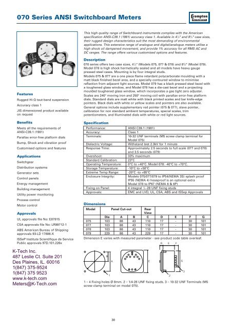
<strong>070</strong> <strong>Series</strong> <strong>ANSI</strong> <strong>Switchboard</strong> <strong>Meters</strong>D.C. VoltmetersD.C. VoltmeterProduct Codes – Sensitivity 1000 ohms / Volt (Accuracy ±1%)***4 1 ⁄2" Square Flange 8 3 ⁄4" Square FlangeRating Scaling* Standard Case Sealed Case Hi-Shock Standard CaseCatalogue No. Catalogue No. Catalogue No.50mV to 800V TO SUIT •/+077-05VA-** 078-05VJ-** 079-05VA-**0-15V 0-15V •/+077-05VA-NDND 078-05VJ-NDND 079-05VA-NDND0-30V 0-30V •/+077-05VA-NLNL 078-05VJ-NLNL 079-05VA-NLNL0-50V 0-50V •/+077-05VA-NTNT 078-05VJ-NTNT 079-05VA-NTNT0-75V 0-75V •/+077-05VA-PBPB 078-05VJ-PBPB 079-05VA-PBPB0-150V 0-150V •/+077-05VA-PZPZ 078-05VJ-PZPZ 079-05VA-PZPZ0-300V 0-300V •/+077-05VA-RXRX 078-05VJ-RXRX 079-05VA-RXRX0-400V 0-400V •/+077-05VA-SCSC 078-05VJ-SCSC 079-05VA-SCSC0-500V 0-500V •/+077-05VA-SFSF 078-05VJ-SFSF 079-05VA-SFSF0-600V 0-600V •/+077-05VA-SJSJ 078-05VJ-SJSJ 079-05VA-SJSJ0-750V 0-750V 077-05VA-SMSM 078-05VJ-SMSM 079-05VA-SMSM0-800V 0-800V 077-05VA-SNSN 078-05VJ-SNSN 079-05VA-SNSNProduct Codes – Zero Centre - Sensitivity 2000 Ohms / Volt(Accuracy ±1%)***150-0-150V 150-0-150V •/+077-05NA-RXRX 078-05NJ-RXRX 079-05NA-RXRX300-0-300V 300-0-300V •/+077-05NA-SJSJ 078-05NJ-SJSJ 079-05NA-SJSJ500-0-500V 500-0-500V •/+077-05NA-SSSS 078-05NJ-SSSS 079-05NA-SSSS600-0-600V 600-0-600V •/+077-05NA-SUSU 078-05NJ-SUSU 079-05NA-SUSUProduct Code – Suppressed Zero***1 - 5V TO SUIT •/+077-05S-LM 078-05S-LM •079-05S-LMFrequency <strong>Meters</strong>Frequency MeterProduct Code –120V Self Contained***4 1 ⁄2" Square Flange 8 3 ⁄4" Square FlangeRating Scaling* Standard Case Sealed Case Hi-Shock Standard CaseCatalogue No. Catalogue No. Catalogue No.50Hz+/-0.15 45-55Hz •/+077-41LA-PNAG-AG 078-41LJ-PNAG-AG •079-41LA-PNAG-AG50Hz+/-0.15 46-54Hz •/+077-41LA-PNAH-AH 078-41LJ-PNAH-AH •079-41LA-PNAH-AH50Hz+/-0.25 45-65Hz •/+077-41LA-PNAJ-AJ 078-41LJ-PNAJ-AJ •079-41LA-PNAJ-AJ60Hz+/-0.25 50-70Hz •/+077-41LA-PNAL-AL 078-41LJ-PNAL-AL •079-41LA-PNAL-AL60Hz+/-0.15 55-65Hz •/+077-41LA-PNAN-AN 078-41LJ-PNAN-AN •079-41LA-PNAN-AN60Hz+/-0.15 56-64Hz •/+077-41LA-PNAO-AO 078-41LJ-PNAO-AO •079-41LA-PNAO-AO60Hz+/-0.08 58-62Hz •/+077-41LA-PNAT-AG 078-41LJ-PNAG-AG •079-41LA-PNAG-AG400Hz+/-1.3 350-450Hz •/+077-41LA-PNBH-BH 078-41LJ-PNBH-BH •079-41LA-PNBH-BH400Hz+/-1.25 360-440Hz •/+077-41LA-PNBI-BI 078-41LJ-PNBI-BI •079-41LA-PNBI-BI400Hz+/- 0.8 380-420Hz •/+077-41LA-PNBK-BK 078-41LJ-PNBK-BK 079-41LA-PNBK-BKAlternative voltage rating 200-250V use code * Other scales are availableRN instead of PN ** Specify scale requiredAlternative voltage rating 380-480V use code *** Case types 077/078/079 use 10-32SE instead of PNUNF terminals. For M5 screw clamp• UL recognised File number E87815 terminals stipulate case type 07538
<strong>070</strong> <strong>Series</strong> <strong>ANSI</strong> <strong>Switchboard</strong> <strong>Meters</strong>Thermal Maximum Demand Directly Heated Element TypeIndicates the maximum average ampere demand of a system. A red resettable slavepointer is driven upscale by the indicating pointer to show maximum average valueof current since the previous setting. 4 1 /2" square flange.SpecificationBurden:Time lag:Accuracy:3.5VA with limiting C.T., 2.5VA without limiting C.T.15 minutes3% 50 or 60HzA.C. Maximum Demand AmmeterProduct Codes5/6A with 20% overload and internal limiting C.T. •077-16EU-LS**5A - without overload, with internal limiting C.T. •077-16EU-LS**- NOThermal / Instantaneous Maximum Demand Ammeter (MDA)Allows instantaneous values of current to be read independently of the thermalindicator. This meter combines a thermal movement, with a rugged shortscale ironvane indicator.SpecificationBurden:Time Lag:Accuracy:4VA with limiting C.T., 3VA without limiting C.T.15 mins3% MDA, 2% Iron Vane 50 or 60HzThermal Instantaneous MaximumDemand AmmeterProduct CodesThermal / Instantaneous MDA5/6A with 20% overload scale and internal limiting C.T. •077-16FU-LS**5A - without 20% overload scale, with internal limiting C.T. •077-16FU-LS** - NODual Range - Thermal Instantaneous3/6A - with 20% overload scale •077-16FU-LK**2.5/5A - without 20% overload scale•077-16FU-LK** - NO6/12A with 20% overload scale and internal limiting C.T. •077-16FU-LV**5/10A - without 20% overload scale with internal limiting C.T. •077-16FU-LV** - NOInstantaneous Maximum Demand Ammeter with SlavePointerDesigned to be compatible with other 4 1 ⁄2" switchboard meters. This instrumentenhances panel appearance and indicates maximum instantaneous values of loadcurrent. The meter incorporates a longscale high torque taut band iron vanemovement to drive the red slave pointer.SpecificationBurden:Product Code5A - without overload scale5VA, Accuracy -1% 50 or 60Hz077-08DA-LS**Instantaneous Maximum DemandAmmeter** Specify scale required• UL recognised39
<strong>070</strong> <strong>Series</strong> <strong>ANSI</strong> <strong>Switchboard</strong> <strong>Meters</strong>A.C. Wattmeters & VarmetersThe Crompton 70 series of A.C. Wattmeters and Varmeters incorporate a DC movingcoil taut band indicator with the Crompton designed micro-circuit Watt transducerPCB to read power on single phase or three phase systems. Varmeters can besupplied with internal phase shifter or with external phase shifter if preferred. In theinterest of standardisation, preferred Wattmeter scale marking for common currentand voltage transformers are listed on the following pages. Instruments may besupplied with zero left or center zero scales at the same list price.ScalingSince Wattmeter and Varmeter current circuits are frequently connected in series,they should have equal current carrying capacity. This means that to assure equalitythe sum of the left and right end-scale values of the Varmeters should be equal to orgreater than the full scale value of the Wattmeter (or the higher of the end-scalevalues if center or offset zero). Instruments 10,000 kilowatts and over are marked inmegawatts. Center zero or offset zero Watt and Varmeters are marked “IN” for leftdeflection and “OUT” for right deflection. Preferred scales may be calculated forWattmeters and varmeters not listed on the charts. Scale Watts must be one of thestandard full scale dial markings shown on the charts.CalibrationFor full load value of Watts or Vars, assuming unity power factor:1ph 2 wire Watts = amps x volts3ph 3 wire Watts = amps x line to line volts x √33ph 4 wire Watts = amps x line to neutral volts x 3Minimum scale values are obtained by multiplying resultant Watts using aboveformula x 0.7 and selecting next highest standard scale.For maximum scale value multiply x 1.3 and select next lowest standard.If scale calculates to an exact listed value use it rather than the next higher orlower value.Note: When ordering Wattmeters and Varmeters specify C.T. ratio, V.T. ratio andrequired scale.SpecificationBurden per element:Current circuit: 2VAVoltage circuit: 1VAAccuracy Class: 1.0Ambient range:0° to +60°C, (32° to 140°F) standard calibration 20°C (68°F)Ambient influence: 0.05% per 1°C maximumOverloads-current: 10 x rating for 5 seconds., 1.2 x continuouslyVoltage:2 x rating for 5 seconds., 1.2 x continuouslyVoltage influence: Accuracy maintained, 80-110% rated voltagePower Factor influence: Accuracy maintained 0.1 lag to 0.1 leadEnclosure code:077: IP54 optional IP55078: IP67079: IP54 optional IP55Response Time:077,078: approximately 2.5 seconds079: approximately 3.5 secondsDielectric test:Live parts to case including panel 2600V RMS for 1 minute40
<strong>070</strong> <strong>Series</strong> <strong>ANSI</strong> <strong>Switchboard</strong> <strong>Meters</strong>Wattmeter/Varmeter Scale Selector GuidePRIMARY POTENTIAL 12KV 14.4KV 24KV 34.5KV 38KV 46KV 92KV 115KV 138KV 345KV 765KVTRANSFORMER VOLTAGE (100:1) (120:1) (200:1) (300:1) (330:1) (400:1) (800:1) (1000:1) (1200:1) (3000:1) (6000:1)SYSTEM VOLTAGE3 PHASE 3 WIRE (L-L) 12KV 14.4KV 24KV 34.5KV 38KV 46KV 92KV 115KV 138KV 345KV 765KVSYSTEM VOLTAGE3 PHASE 4 WIRE (L-N) 6900 8300 13.8KV 20KV 22KV 26.5KV 53KV 66KV 80KV 200KV 440KVCURRENT TRANSFORMERRATIO NORMAL 500KW 600KW 1000KW 1500KW 1500KW 1500KW 3000KW 5000KW 6000KW 15MW 30MW25/5 MAX. 650 800 1200 1500 2000 2500 200 200 250 300 400(5:1) MIN. 325 400 600 750 1000 1250 100 100 125 150 200RATIO NORMAL 1000KW 1200KW 2000KW 3000KW 3000KW 3500KW 8000KW 10MW 12MW 30MW 60MW50/5 MAX. 1200 1500 2500 3500 4000 5000 10MW 12 15 35 80(10:1) MIN. 600 750 1250 1750 2000 2500 5000KW 6000KW 7500KW 15 40RATIO NORMAL 1500KW 1800KW 3000KW 4000KW 5000KW 5000KW 10MW 15MW 15MW 45MW 100MW75/5 MAX. 2000 2000 4000 5000 6000 7500 15 15 20 50 125(15:1) MIN. 1000 1000 2000 2500 3000 3000 7500KW 7500KW 10 25 50RATIO NORMAL 2000KW 2500KW 4000KW 6000KW 6000KW 7500KW 15MW 20MW 25MW 60MW 125MW100/5 MAX. 2500 3000 5000 7500 8000 10MW 20 25 30 70 150(20:1) MIN. 1250 1500 2500 3000 4000 5000KW 10 12.5 15 35 75RATIO NORMAL 3000KW 3500KW 6000KW 10MW 10MW 10MW 20MW 30MW 35MW 90MW 200MW150/5 MAX. 4000 4000 4000 10 12 15 30 35 40 100 250(30:1) MIN. 2000 2000 2000 5000KW 6000KW 7500KW 15 15 20 50 100RATIO NORMAL 4000KW 4500KW 8000KW 12MW 12MW 15MW 30MW 35MW 50MW 100MW 250MW200/5 MAX. 5000 6000 5000 15 15 20 40 50 60 150 300(40:1) MIN. 2500 3000 2500 7500KW 7500KW 10 20 25 30 75 150RATIO NORMAL 6000KW 7000KW 12MW 18MW 18MW 20MW 45MW 60MW 75MW 150MW 400MW300/5 MAX. 8000 8000 15 20 25 30 60 75 80 200 500(60:1) MIN. 4000 4000 7.5 10 12.5 15 30 30 40 100 250RATIO NORMAL 8000KW 10MW 15MW 24MW 25MW 30MW 60MW 80MW 100MW 200MW 500MW400/5 MAX. 10MW 12 20 30 30 40 80 100 120 300 600(80:1) MIN. 5000KW 6000KW 10 15 15 20 40 50 60 150 300RATIO NORMAL 12MW 15MW 25MW 35MW 40MW 45MW 90MW 100MW 150MW 350MW 800KW600/5 MAX. 15 18 30 40 50 60 120 150 180 450 1000(120:1) MIN. 7500KW 10 15 20 25 30 60 75 75 225 500RATIO NORMAL 15MW 20MW 30MW 50MW 50MW 60MW 120MW 150MW 200MW 500MW 1000MW800/5 MAX. 20 25 40 60 60 80 150 200 200 600 1200(160:1) MIN. 10 12.5 20 30 30 40 75 100 100 300 600RATIO NORMAL 20MW 25MW 40MW 50MW 60MW 75MW 150MW 200MW 250MW 600MW 1200MW1000/5 MAX. 25 30 50 60 80 100 200 250 300 750 1500(200:1) MIN. 12.5 15 25 30 40 50 100 125 150 300 750RATIO NORMAL 25MW 30MW 50MW 60MW 80MW 100MW 175MW 250MW 300MW 750MW 1500MW1200/5 MAX. 30 35 60 80 100 120 200 300 350 900 2000(240:1) MIN. 15 20 30 40 50 60 100 150 175 450 1000RATIO NORMAL 30MW 35MW 60MW 75MW 100MW 120MW 250MW 3000MW 350MW 900MW 2000MW1500/5 MAX. 40 40 80 100 120 150 300 350 450 1000 2500(300:1) MIN. 20 20 40 50 60 75 150 175 225 500 1250RATIO NORMAL 40MW 50MW 80MW 100MW 120MW 150MW 300MW 400MW 5000MW 1000MW 2500MW2000/5 MAX. 50 60 100 150 150 200 400 500 600 1500 3000(400:1) MIN. 25 30 50 75 75 100 200 250 300 750 1500RATIO NORMAL 60MW 75MW 100MW 150MW 200MW 200MW 400MW 600MW 700MW 1500MW 3500MW3000/5 MAX. 80 80 150 200 250 300 500 750 900 2000 5000(600:1) MIN. 40 40 75 100 125 150 250 350 450 1000 2500RATIO NORMAL 80MW 100MW 150MW 200MW 250MW 300MW 5000MW 800MW 1000MW 2000MW 500MW4000/5 MAX. 100 125 200 300 300 400 800 1000 1200 3000 6000(800:1) MIN. 50 60 100 150 150 200 400 500 600 1500 3000RATIO NORMAL 100MW 125MW 200MW 250MW 300MW 4000MW 750MW 1000MW 1200MW 3000MW 6000MW5000/5 MAX. 120 150 250 300 400 500 1000 1200 1500 3500 8000(1000:1) MIN. 60 75 125 150 200 250 500 600 750 1750 400RATIO NORMAL 120MW 150MW 250MW 350KW 400MW 450MW 1000MW 1200MW 1500MW 3500MW 8000MW6000/5 MAX. 150 175 300 400 500 600 1200 1500 1750 4000 10000(1200:1) MIN. 75 80 150 200 250 300 600 750 800 2000 500042
<strong>070</strong> <strong>Series</strong> <strong>ANSI</strong> <strong>Switchboard</strong> <strong>Meters</strong>A.C. WattmetersA.C. WattmeterProduct Codes – 1 element, transformer rated. 50/60Hz.Taut Band. Integral transducer. Accuracy 1.0%. 50/60HzMeasured 4 1 ⁄2" Square Flange 8 3 ⁄4" Square FlangeSystem Scales Standard Case Sealed Case Standard CaseCatalogue No. Hi-Shock Catalogue No.Catalogue No.PhasesWiresAmperes1 VA max. BurdenVolts1 VA max. Burden1 2 5 120V TO SUIT •/+077-215A-QQ** 078-215J-QQ** •079-215A-QQ**1 2 5 240V TO SUIT 077-215A-QS** 078-215J-QS** 079-215A-QS**For connection diagram please see Fig. 21 page 60.Product Codes – 2 element, transformer rated. 50/60Hz.Taut Band. Integral transducer. Accuracy 1.0%. 50/60Hz3 3 5 120V TO SUIT •/+077-218A-QQ** 078-218J-QQ** •079-218A-QQ**3 3 5 208V TO SUIT •/+077-218A-QR** 078-218J-QR** •079-218A-QR**3 3 5 240V TO SUIT •/+077-218A-QS** 078-218J-QS** 079-218A-QS**3 3 5 380V TO SUIT •/+077-218A-QX** 078-218J-QX** 079-218A-QX**3 3 5 480V TO SUIT •/+077-218A-QT** 078-218J-QT** 079-218A-QT**For connection diagram please see Fig. 25 page 60.Product Codes – 21⁄2 element, transformer rated. 50/60Hz.Taut Band. Integral transducer. Accuracy 1.0%. 50/60Hz3 4 5 69V TO SUIT •/+077-219A-QL** 078-219J-QL** •079-219A-QL**3 4 5 120V TO SUIT •/+077-219A-QQ** 078-219J-QQ** •079-219A-QQ**3 4 5 277V TO SUIT 077-219A-QY** 078-219J-QY** 079-219A-QY**3 4 5 346V TO SUIT 077-219A-QZ** 078-219J-QZ** 079-219A-QZ**For connection diagram please see Fig. 28 page 60.Product Codes – Phase Shifting TransformersFor use with above Wattmeters, when VAr measurement with external phase shifter is required.3 3 120V 855-956A-PR 855-956J-PR 855-956A-PR3 4 120V 855-957A-PR 855-957J-PR 855-957A-PR3 4 69V 855-957A-NZ 855-957J-NZ 855-957A-NZA.C. VarmetersProduct Codes – 2 element, transformer rated. 50/60Hz.Taut Band. Integral transducer. Accuracy 1.0%. 50/60Hz3 3 5 120V TO SUIT •/+077-31LA-QQ** 078-31LJ-QQ**3 3 5 208V TO SUIT •/+077-31LA-QR**-C6 078-31LJ-QR**3 3 5 240V TO SUIT 077-31LA-QS** 078-31LJ-QS**3 3 5 380V TO SUIT 077-31LA-QX** 078-31LJ-QX**3 3 5 480V TO SUIT 077-31LA-QT** 078-31LJ-QT**For connection diagram please see Fig. 32 page 61.A.C. VarmeterProduct Codes – 21⁄2 element, transformer rated. 50/60Hz.Taut Band. Integral transducer. Accuracy 1.0%.50/60Hz3 4 5 120V TO SUIT •/+077-31UA-QQ** 078-31UJ-QQ** •079-31UA-QQ**3 4 5 208V TO SUIT 077-31UA-QR** 078-31UJ-QR** •079-31UA-QR**3 4 5 480V TO SUIT 077-31UA-QT** 078-31UJ-QT** 079-31UA-QT**For connection diagram please see Fig. 32 page 61.• UL recognised File # E87815 + CSA Approved File # LR52592** Specify C.T. (Current Transformer) and V.T. (Voltage Transformer) ratios if used, andpreferred scale at time of ordering.43
<strong>070</strong> <strong>Series</strong> <strong>ANSI</strong> <strong>Switchboard</strong> <strong>Meters</strong>RTD Temperature <strong>Meters</strong>*RTD Temperature MeterProduct Codes – Accuracy 1.0% of span.Self-contained for 10 Ohm copper or 100 Ohm platinum RTD. (ResistanceTemperature Detector) - Specify copper or platinum at time of ordering.4 1 ⁄2" Square FlangeRating Scaling* Standard Case Sealed Case Hi-ShockCatalogue No.Catalogue No.110/130V 20-140°C 077-45RA-**QF-PQ 078-45RJ-**QF-PQ50/60Hz110/130V 0-150°C 077-45RA-**QE-PQ 078-45RJ-**QE-PQ50/60Hz110/130V 0-200°C 077-45RA-**QG-PQ 078-45RJ-**QG-PQ50/60HzFor connection diagrams please see Fig. 17 page 59.Thermocouple Temperature <strong>Meters</strong>Product Code – Accuracy 1% of span.Suitable for type J and K. Cold junction compensation and thermocouple break indication isprovided. Specifiy type J or K and temperature at time of ordering.4 1 ⁄2" Square FlangeRatingStandard Case Catalogue No.110/130V 077-45TA-••PM50/60HzFor connection diagrams please see Fig. 18 page 59.Tap Position IndicatorProduct CodeTo show transformer tap, hoist or valve position using 3 wire system for 1-18 tap positionsusing 400 Ohm steps.4 1 ⁄2" Square Flange 8 3 ⁄4" Square FlangeRating Scaling* Standard Case Sealed Case Hi-Shock Standard CaseCatalogue No. Catalogue No. Catalogue No.110/220/240V 1-18 taps 077-45P- Not available Not available50/60HzFor connection diagrams please see Fig. 20 page60.Select nearest higher rated voltmeter and specify requirement• UL recognised File # E87815 * Other ranges available upon•• JT for type J, KT for type K thermocouplerequest - Consult Factory.** RI for 10 ohm Copper or R2 for100ohm platinum.*** Specify input and scale44
<strong>070</strong> <strong>Series</strong> <strong>ANSI</strong> <strong>Switchboard</strong> <strong>Meters</strong>Elapsed Time <strong>Meters</strong>Elapsed Time MeterProduct Codes – 99,999.99 hours, non reset. Burden 2.5VA. 50or 60HzSynchronous motor running time meter with a running indicator.4 1 ⁄2" Square Flange 8 3 ⁄4" Square FlangeRating Standard Case Sealed Case Hi-Shock Standard CaseCatalogue No. Catalogue No. Catalogue No.110/130V 50Hz •077-155A-PNZH-C5 078-155J-PNZH-C5 Not available200/250V 50Hz •077-155A-RNZH-C5 078-155J-RNZH-C5 Not available480V 50Hz •077-155A-SEZH-C5 078-155J-SEZH-C5 Not available110/130V 60Hz •077-156A-PNZH-C6 078-156J-PNZH-C6 Not available200/250V 60Hz •077-156A-RNZH-C6 078-156J-RNZH-C6 Not available480V 60Hz •077-156A-SEZH-C6 078-156J-SEZH-C6 Not available12/24/40/110V D.C. 077-151A-A.C. Phase Sequence, Phase Failure IndicatorsProduct Codes – Neon Bulb Type. Burden 2.5VA2 neon bulbs for phase sequence indication - first marked correct 1-2-3, secondmarked incorrect 3-2-1. 3 neon bulbs for phase failure indication - first marked 1,second marked 2, third marked 3.4 1 ⁄2" Square Flange 8 3 ⁄4" Square FlangeRating Standard Case Sealed Case Hi-Shock Standard CaseCatalogue No. Catalogue No. Catalogue No.100/150V 50/60Hz 077-12PA-P2C6 Not available Not available151/300V 50/60Hz 077-12PA-P3C6 Not available Not available301/500V 50/60Hz 077-12PA-P4C6 Not available Not availableFor connection diagrams please see Fig. 1 page 58.A.C. Phase Sequence and Phase FailureIndicatorD.C. Indicators for Tachometer GeneratorsProduct Code4 1 ⁄2" Square Flange 8 3 ⁄4" Square FlangeRating Standard Case Sealed Case Hi-Shock Standard CaseCatalogue No. Catalogue No. Catalogue No.D.C. Volts 077-052A-*** 078-052J-*** 079-052A-***Select nearest higher rated voltmeter and specify requirement• UL recognised File # E87815 * Other ranges available upon•• JT for type J, KT for type K thermocouplerequest - Consult Factory.** RI for 10 ohm or R2 to 100ohmplatinum.*** Specify input and scale45
<strong>070</strong> <strong>Series</strong> <strong>ANSI</strong> <strong>Switchboard</strong> <strong>Meters</strong>A.C. Power Factor MeterA.C. Power Factor MeterSpecificationRatings, self-contained: Current windings 5 amperes.Voltage windings minimum 50 volts, maximum 600 voltsAccuracy Class: 1.0Overshoot: 33%External Temperature 0.5% fid max.Influence:External Field Influence: 3% fid max.Frequency Range: 50Hz or 60Hz standard, 25-3000Hz optional (Specify)Frequency Influence: Single phase instruments, 59 to 61Hz 1.0% fid max.Polyphase instruments ±10% deviation from 69Hz: 1.0%Overload capacity: Current coils 1000% momentarily, 100% for 15 minutesand 25% indefinitely.Voltage circuits 25% indefinitely.Burdens:Each current circuit, 1.5VA approxEach voltage circuit 1VA approxMeasuring systems 077-427 - 3 or 4 wireRanges available:Lag 0.5-1 - 0.5 lead power factorLag 0.2-1 - 0.8 lead power factorJIS dimension product available on request. Instruments may be used on loadsdown to 20% of current rating and between 90% and 110% of voltage rating.Product Codes – Balanced Load Accuracy ±1%Measured 4 1 ⁄2" Square Flange 8 3 ⁄4" Square FlangeSystem Scales Standard Case Sealed Case Standard CaseCatalogue No. Hi-Shock Catalogue No.Catalogue No.PhasesWires1 2 5 120V 0.5-1-0.5 •/+077-425A-QQAD 078-425J-QQAD •079-425A-QQAD1 2 5 240V 0.5-1-0.5 •/+077-425A-QSAD 078-427J-QSAD •079-427A-QSAD3 3⁄4 5 120V 0.5-1-0.5 •/+077-427A-QQAD 078-427J-QQAD •079-427A-QAAD3 3⁄4 5 208V 0.5-1-0.5 •/+077-427A-QRAD 078-427J-QRAD •079-427A-QRAD3 3⁄4 5 240V 0.5-1-0.5 •/+077-427A-QSAD 078-427J-QSAD •079-427A-QSAD3 3⁄4 5 480V 0.5-1-0.5 077-427A-QTAD 078-427J-QTAD 079-427A-QTADFor connection diagrams please see Fig. 13 & 15 page 59.Product Codes – Unbalanced Load Accuracy ±1%PhasesWiresAmperes2 VA max. BurdenMeasured 4 1 ⁄2" Square Flange 8 3 ⁄4" Square FlangeSystem Scales Standard Case Sealed Case Standard CaseCatalogue No. Hi-Shock Catalogue No.Catalogue No.Amperes2 VA max. BurdenVolts1 VA max. BurdenVolts1 VA max. Burden3 3 5 120V 0.5-1-0.5 077-TFUA-QQAD – –3 3 5 240V 0.5-1-0.5 077-TFUA-QSAD – –For connection diagrams please see Fig. 12 page 59.• UL Recognised File # E87815+ CSA Approved File # LR5259246
<strong>070</strong> <strong>Series</strong> <strong>ANSI</strong> <strong>Switchboard</strong> <strong>Meters</strong>360° Power Factor360° Power Factor MeterSpecificationRatings, self-contained: Current windings minimum, 0.5 amps, maximum20 amps. Voltage windings min. 50 volts, maximum240 volts, for higher voltages up to 480 volts anexternal box is supplied.Normal Operating Position: On vertical panel unless otherwise specified at the timeof order.Position Influence: Not more than 1% of scale length for up to 60° tilt fromnormal operating positionAccuracy Class: 1.0Overshoot: 33%External Temp. Influence: 0.5% fid. max.External Field Influence: 3% fid. maxFrequency Influence: Single phase instruments from 59 to 61Hz 1% max.fid. max. Polyphase instrument ±10% deviation from60Hz: 1% fid. max.Overload Capacity: Current coils 1000% momentarily, 100% for 15 minutes,and 50% indefinitely.Voltage circuits 50% indefinitely.Characteristics 077-132 077-136A V A VImpedance ohms: 0.162 3380 0.043 3380Resistance ohms: 0.147 3300 0.04 3300Resistance ohms: 0.082 750 0.016 750Watts: 3.5 1.39 1.0 1.30Volt-Amperes: 4.05 1.42 1.07 1.42Reactive VA: 2.03 0.281 0.4 0.281Power Factor: 0.86 0.96 0.93 0.98Product Codes – Rotary Power Factor - 360°3 3⁄4 5 120V 0-1-0 077-136A-QQAB 078-136J-QQAB 079-136A-QQAB3 3⁄4 5 208V 0-1-0 077-136A-QRAB 078-136J-QRAB 079-136A-QRAB3 3 5 120V 0-1-0 077-132A-QQAB 078-132J-QSAB 079-132A-QSAB3 3 5 208V 0-1-0 077-132A-QRAB 078-132J-QTAB 079-132A-QTABFor connection diagrams please see Fig. 4, 6 & 7 page 58.Rotating iron 360° products are only suitable for use on 50 and 60 Hz systems.3 Phase 4 Wire Power Factor <strong>Meters</strong> Model -136 unbalanced load, -132are connected L-L ie.balanced load120V L-N system will be rated at 208V L-L.• UL Recognised File # E87815+ CSA Approved File # LR5259247
<strong>070</strong> <strong>Series</strong> <strong>ANSI</strong> <strong>Switchboard</strong> <strong>Meters</strong>360° Rotary Synchroscope360° Rotary SynchroscopeSpecificationRating, self-contained: 120V A.C.Frequency rating:50 or 60Hz (specify), 400Hz optionalNormal Operating Position: On vertical panel unless otherwise specified at timeof orderPosition Influence: Not more than 3.6 mechanical degrees deviation for upto 60° tilt from normal operating position.Accuracy:2 degreesOvershoot:33% maximumResponse time:3 seconds maximum for 180° deflectionSensitivity at synchronism: 3 electrical degrees maximumExternal field influence: 3% maximum in 5 oersted fieldPull in frequency:58HzDrop-out frequency: 57HzDielectric test:Live parts to case, including panel: 2600V RMSfor 1 minute.Between running and 1500V RMS for 1 minuteincoming circuits:Overload capacity: 50% indefinitelyCharacteristics <strong>Inc</strong>oming circuit Running circuitImpedance ohms: 4670 5335Resistance ohms: 4020 5240Resistance ohms: 2380 1058Reactive Volt amps: 1.57 0.535Volt-amps: 3.08 2.7Power factor: 0.86 0.98Watts: 2.66 2.65Product Codes – Pivot and Jewel4 1 ⁄2" Square Flange 8 3 ⁄4" Square FlangeRating Scaling* Standard Case Sealed Case Hi-Shock Standard CaseCatalogue No. Catalogue No. Catalogue No.120V 50Hz SLOW FAST •/+077-145A-PRAE-C5 078-145J-PRAE-C5 •079-145A-PRAE-C5120V 60Hz SLOW FAST •/+077-146A-PRAE-C6 078-146J-PRAE-C6 •079-146A-PRAE-C6120V 400Hz SLOW FAST 077-144A-PRAE-C4 078-144J-PRAE-C4 079-144A-PRAE-C4For connection diagrams please see Fig. 10 page 59.Alternate voltage of 240V, use code RRinstead of PR.• UL Recognised File # E87815+ CSA Approved File # LR5259248
<strong>070</strong> <strong>Series</strong> <strong>ANSI</strong> <strong>Switchboard</strong> <strong>Meters</strong>360° A.C. LED SynchroscopeSpecificationVoltage:120, 240, 480 Volts A.C. or via P.T.Frequency:40/65HzBurden @ 60Hz:4VA maximumSuitable for single or three phase systemsSafety: IEC1010-1(300V A.C. rms installation degree 2)Dielectric:4kV rms for 1 minuteIsolation:BUS/GEN/RELAYVibration:To Lloyds shipping specification360° A.C. LED SynchroscopeProduct Codes4 1 ⁄2" Square FlangeRating Scaling Standard CaseCatalogue No.120V 40/65Hz SLOW FAST 077-14AU-PQYY-FQ240V 40/65Hz SLOW FAST 077-14AU-RRYY-FQ480V 40/65Hz SLOW FAST 077-14AU-SEYY-FQFor connection diagrams please see Fig. 8 page 58.A.C. Synchrocheck Relay and LED 360° SynchroscopeSpecificationVoltage:110/120V (115V nominal)220/240V (230V nominal)380/480V (430V nominal)Phase Difference: +0 to 20° ±1°Voltage Difference: +0 to 20% ±2%Time Delay: 0 to 2.5 seconds +10%A.C. Synchrocheck Relay& LED 360° SynchroscopeProduct Codes4 1 ⁄2" Square FlangeRating Scaling Standard CaseCatalogue No.Live Bus110/120V 40/65Hz SLOW FAST 077-14GU-POYY-FQ220/240V 40/65Hz SLOW FAST 077-14GU-RSYY-FQ380/480V 40/65Hz SLOW FAST 077-14GU-SZYY-FQDead Bus110/120V 40/65Hz SLOW FAST 077-14HU-POYY-FQ220/240V 40/65Hz SLOW FAST 077-14HU-RSYY-FQ380/480V 40/65Hz SLOW FAST 077-14HU-SZYY-FQLive Bus120V 40/65Hz SLOW FAST 077-14LU-PQYY-FQ240V 40/65Hz SLOW FAST 077-14LU-RRYY-FQ480V 40/65Hz SLOW FAST 077-14LU-SEYY-FQDead Bus120V 40/65Hz SLOW FAST 077-14DU-PQYY-FQ240V 40/65Hz SLOW FAST 077-14DU-RRYY-FQ480V 40/65Hz SLOW FAST 077-14DU-SEYY-FQFor connection diagrams please see Fig. 9 page 58.In the 0.77-14G and 0.77-14H models, the generator voltage is free to track the busvoltage (+ the voltage difference preset) over the input voltage range. In the 077-14L and 077-14D models, the generator voltage is to match the nominal input (bus)voltage specified (within the voltage difference preset).49
<strong>070</strong> <strong>Series</strong> <strong>ANSI</strong> <strong>Switchboard</strong> <strong>Meters</strong>D.C. Transducer IndicatorsD.C. Transducer IndicatorProduct Codes4 1 ⁄2" Square Flange 8 3 ⁄4" Square FlangeRating Scaling* Standard Case Sealed Case Hi-Shock Standard CaseCatalogue No. Catalogue No. Catalogue No.WATTS 1mA TO SUIT •/+077-055A-FA** 078-055J-FA** •079-055A-FA**VARS 1mA TO SUIT •/+077-056A-FA** 078-056J-FA** •079-056A-FA**FREQUENCY 1mA TO SUIT •/+077-053A-FA** 078-053J-FA** •079-053A-FA**POWER FACTOR 1mA TO SUIT •/+077-054A-FA** 078-054J-FA** •079-054A-FA**A.C. AMPS 1mA TO SUIT •/+077-05AA-FA** 078-05AJ-FA** •079-05AA-FA**A.C. VOLTS 1mA TO SUIT •/+077-05VA-LT** 078-05VJ-LT** •079-05VA-LT**SPEED 1mA TO SUIT •/+077-052A-FA** 078-052J-FA** •079-052A-FA**VA 1mA TO SUIT •/+077-057A-FA** 078-057J-FA** •079-057A-FA**For use with the following transducers:- * Case types 077/078/079 use 10-32Watts, VArs, Frequency, Power Factor,UNF terminals. For M5 screw clampA.C. Amperes, A.C. Volts & Temperature terminals stipulate case type 075** Specify scale. Input: 1mA D.C. for4/20mA change “FA” to “HG”A.C. Watt & Watt Hour <strong>Meters</strong>Moving coil indication gives instantaneous reading of Watts. Self Contained circuitrydrives an impulse counter to give Watt hour indication.Product Codes – Transducer Driven Accuracy ±1%.With internal linear integrator and six digit impulse counter. Externally powered.4 1 ⁄2" Square Flange 8 3 ⁄4" Square FlangeRating Scaling Standard Case Sealed Case Hi-Shock Standard CaseCatalogue No. Catalogue No. Catalogue No.120V, 240V 1mA TO SUIT 077-KHAU-FA** 078-KHAJ-FA** Not available50/60Hz 4-20mA 077-KHAU-HG** 078-KHAJ-HG**For connection diagrams please see Fig. 19 page 59.A.C. Watt/Watt Hour MeterProduct Codes – Self Contained - Accuracy instantaneous 1%.Kilowatt hour 0.5% of pulse rate/hour.Single element. Transformer rated 50/60Hz. Hi-Q Taut Band. Integral transducer.Measured 4 1 ⁄2" Square Flange 8 3 ⁄4" Square FlangeSystem Scales Standard Case Sealed Case Standard CaseCatalogue No. Hi-Shock Catalogue No.Catalogue No.PhasesWiresAmperes2VA max. BurdenVolts1 VA max. Burden1 2 5 120 TO SUIT 077-KHBU-QQ** 078-KHBJ-QQ** Not availableFor connection diagrams please see Fig. 21 page 60.2 element. Transformer rated. 50/60Hz. Hi-Q Taut Band. Integral transducer.3 3 5 120 TO SUIT 077-KHEU-QQ** 078-KHEJ-QQ** Not available3 3 5 208 TO SUIT 077-KHEU-QR** 078-KHEJ-QR** Not availableFor connection diagrams please see Fig. 25 page 60.2 1 ⁄2 Element.Transformer rated. 50/60Hz. Hi-Q Taut Band. Integral transducer.3 4 5 69 TO SUIT 077-KHGU-QL** 078-KHGJ-QL** Not available3 4 5 120 TO SUIT 077-KHGU-QQ** 078-KHGJ-QQ** Not available3 4 5 277 TO SUIT 077-KHGU-QY** 078-KHGJ-QY** Not availableFor connection diagrams please see Fig. 28 page 60.** Specify pulse rate and external power supply • UL Recognised File # E87815+ CSA Approved File # LR5259250
<strong>070</strong> <strong>Series</strong> <strong>ANSI</strong> <strong>Switchboard</strong> <strong>Meters</strong>Connection DiagramsFig. 1 Model 077-12PPhase Sequence Indicator 3 phase 3or 4 wire systems.Fig. 2 Model 077-137360° Dynamometer Power FactorIndicator Single Phase.Fig. 3 Model 077-131360° deg Dynamometer Power FactorIndicator 3 Phase 3 or 4 Wire BalancedLoad (3 Currents 1 Voltage).Fig. 4 Models 077-132, 078-132J360° Dynamometer Power FactorIndicator 3 Phase 3 or 4 Wire BalancedLoad (1 Current 3 Voltages).Fig. 5 Model 078-132B360° Dynamometer Power factorIndicator Indicator 3 Phase 3 or 4 WireBalanced Load (1 Current 3 Voltages).Fig. 6 Models 077-136, 077-136A,078-136J360° Dynamometer Power factorIndicator 3 Phase 3 or 4 WireUnbalanced Load.Fig. 7 Model 078-136B360° Dynamometer Power factorIndicator 3 Phase 3 or 4 WireUnbalanced Load.Fig. 8 Models 077-14A360° LED Synchroscope.Fig. 9 Models 077-14D, 077-14G,077-14H, 077-14L360° LED Synchroscope and SynchroCheck relay.58
<strong>070</strong> <strong>Series</strong> <strong>ANSI</strong> <strong>Switchboard</strong> <strong>Meters</strong>Connection DiagramsFig. 10 Models 077-144, 077-145077-146, 077-147, 078-144J, 078-145J078-146J, 078-147J, 079-144, 079-145079-146360 Degree Dynamometer Synchroscope.Fig. 11 Models 078-144B, 078-145B078-146B, 078-147B360 Degree Dynamometer Synchroscope.Fig. 12 Model 077-TFUPower Factor Meter 3 Phase 3 WireUnbalanced Load.Fig. 13 Models 077-425, 078-425J079-425Electronic Phase Angle Meter SinglePhase.Fig. 14 Model 078-425BElectronic Phase Angle Meter SinglePhase.Fig. 15 Models 075-427, 077-427078-427J, 079-427Electronic Phase Angle Meter 3 phase 3or 4 wire Balanced Load.Fig. 16 Model 078-427BElectronic Phase Angle Meter 3 phase 3or 4 wire Balanced Load.Fig. 17 Models 077-45R, 078-45RTemperature Indicator for ResistanceTemperature Detector (RTD).Fig. 18 Model 077-45TTemperature Indicator for ThermocoupleDetector.Fig. 19 Models 077-KHA, 078-KHAAC Kilowatts/Kilowatthours (Transducer)Indicator.59
<strong>070</strong> <strong>Series</strong> <strong>ANSI</strong> <strong>Switchboard</strong> <strong>Meters</strong>Connection DiagramsFig. 20 Model 077-45PTap Position Indicator.Fig. 21 Models 077-215, 077-KHB078-215J, 078-KHBJ, 079-215Wattmeter Single Phase.Fig. 22 Model 078-215B, 078-KHBBWattmeter Single Phase.Fig. 23 Models 077-216, 078-216JWattmeter 3 Phase 3 Wire BalancedLoad.Fig. 24 Model 078-216BWattmeter 3 Phase 3 Wire BalancedLoad.Fig. 25 Models 077-218, 077-KHE078-218J, 078-KHEJ, 079-218Wattmeter 3 Phase 3 Wire UnbalancedLoad.Fig. 26 Models 078-218B, 078-KHEBWattmeter 3 Phase 3 Wire UnbalancedLoad.Fig. 27 Model 077-21DWattmeter 3 Phase 4 Wire BalancedLoad.Fig. 28 Models 077-219, 077-KHG078-219J, 078-KHGJ, 079-219Wattmeter 3 Phase 4 Wire UnbalancedLoad.60
<strong>070</strong> <strong>Series</strong> <strong>ANSI</strong> <strong>Switchboard</strong> <strong>Meters</strong>Connection DiagramsFig. 29 Models 078-219B, 078-KHGBWattmeter 3 Phase 4 Wire UnbalancedLoad.Fig. 30 Models 077-21BWattmeter 3 Phase 3 Wire BalancedLoad 2 Reverse Connected CTs.Fig. 31 Model 077-21FWattmeter 3 Phase 4 Wire UnbalancedLoad Delta Connected CTs.Fig. 32 Models 077-31L, 078-31LJVarmeter 3 Phase 3 Wire UnbalancedLoad.Fig. 33 Models 077-315Varmeter 3 Phase 3 or 4 Wire BalancedLoad.Fig. 34 Model 077-319Varmeter 3 Phase 4 Wire UnbalancedLoad.Fig. 35 Models 077-31U, 077-KXG078-31U, 079-31UVarmeter 3 Phase 4 Wire UnbalancedLoad.Fig. 36 Model 077-31FVarmeter 3 Phase 4 Wire UnbalancedLoad Delta Connected CTs.Fig. 37 Model 077-DW5LED Digital/Analogue Wattmeter SinglePhase.61
<strong>070</strong> <strong>Series</strong> <strong>ANSI</strong> <strong>Switchboard</strong> <strong>Meters</strong>Connection DiagramsFig. 38 Model 077-DW8LED Digital/Analogue Wattmeter 3 Phase3 Wire Unbalanced Load.Fig. 39 Model 077-DW9LED Digital/Analogue Wattmeter 3 Phase4 Wire Unbalanced Load.Fig. 40 Model 077-DXLLED Digital/Analogue Varmeter 3 Phase 3Wire Unbalanced Load.Fig. 41 Model 077-DXULED Digital/Analogue Varmeter 3 Phase4 Wire Unbalanced Load.Fig. 42 Model 077-DP5LED Digital/Analogue Phase Angle MeterSingle Phase.Fig. 43 Model 077-DP7LED Digital/Analogue Phase Angle Meter3 Phase 3 or 4 Wire Balanced Load.Fig. 44 Model 077-DZLLED Digital/Analogue Frequency Meter.Fig. 45 Models 077-DI2, 077-DIA077-DIB, 077-DIC, 077-DIN, 077-DIT077-DIV, 077-DIWLED Digital/Analogue Meter.Fig. 46 Models 077-DA2, 077-DAA077-DAB, 077-DAK, 077-DAT077-DAV, 077-DAWLCD Digital/Analogue Meter.62


