Xtreme Tier III Forklift XR1045 Hydraulic System
Xtreme Tier III Forklift XR1045 Hydraulic System
Xtreme Tier III Forklift XR1045 Hydraulic System
- No tags were found...

Create successful ePaper yourself
Turn your PDF publications into a flip-book with our unique Google optimized e-Paper software.
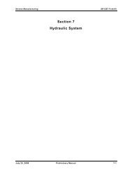
<strong>Xtreme</strong> Manufacturing<strong>XR1045</strong> <strong>Forklift</strong>Section 7<strong>Hydraulic</strong> <strong>System</strong>September 12, 2008 Preliminary Manual 7-1
<strong>Xtreme</strong> Manufacturing<strong>XR1045</strong> <strong>Forklift</strong>Figure 7-1. <strong>Hydraulic</strong> Tank AssemblySeptember 12, 2008 Preliminary Manual 7-2
<strong>Xtreme</strong> Manufacturing<strong>XR1045</strong> <strong>Forklift</strong>Table 7-1. <strong>Hydraulic</strong> Tank AssemblyFigure &Item No.Part No. Description Quantity Use On– 26641-001 <strong>Hydraulic</strong> tank assembly – –7-1-1 26640-001 <strong>Hydraulic</strong> tank assembly 1 –7-1-2 12856-000 Temperature switch 1 –7-1-3 11700-014 Fitting STR 08MFS-08MB 1 –7-1-4 11700-028 Fitting STR 16MFS-20MB 1 –7-1-5 11702-007 Fitting elbow 90 -08MBA-06MFS 1 –7-1-6 11698-008 Plug ext hex HD -12MB 3 –7-1-7 12355-000 Shock mount 1-3/8 dia 4 –Refer to Section 1 for the definition of acronyms and abbreviations used in the Description Column.September 12, 2008 Preliminary Manual 7-3
<strong>Xtreme</strong> Manufacturing<strong>XR1045</strong> <strong>Forklift</strong>Figure 7-2. <strong>Hydraulic</strong> Tank Lid AssemblySeptember 12, 2008 Preliminary Manual 7-4
<strong>Xtreme</strong> Manufacturing<strong>XR1045</strong> <strong>Forklift</strong>Table 7-2. <strong>Hydraulic</strong> Tank Lid AssemblyFigure &Item No.Part No. Description Quantity Use On– 26715-002 <strong>Hydraulic</strong> tank lid assembly – –7-2-1 26714-001 Filler breather plate weldment 1 –7-2-2 12250-001 Seal O-ring 6.484 ID 1 –7-2-3 11698-011 Plug ext hex HD -20MB 1 –7-2-4 14368-000 Breather 1 –Refer to Section 1 for the definition of acronyms and abbreviations used in the Description Column.September 12, 2008 Preliminary Manual 7-5
<strong>Xtreme</strong> Manufacturing<strong>XR1045</strong> <strong>Forklift</strong>Figure 7-3. High-Pressure Filter/Steering Valve AssemblySeptember 12, 2008 Preliminary Manual 7-6
<strong>Xtreme</strong> Manufacturing<strong>XR1045</strong> <strong>Forklift</strong>Table 7-3. High-Pressure Filter/Steering Valve AssemblyFigure &Item No.Part No. Description Quantity Use On– 25763-002 High-pressure filter/steering valveassembly– –7-3-1 14359-000 High pressure filter 1 –7-3-2 14242-000 Steering priority valve 1 –7-3-3 11651-009 Fitting STR -20MBA-20MB 1 –7-3-4 11702-001 Fitting elbow 90 -04MBA-04MFS 2 –7-3-5 11700-028 Fitting STR 16MFS-20MB 2 –7-3-6 11707-007 Fitting tee -8MFS-12MBA-8MFS 1 –7-3-7 14360-000 Filter element 1 –Refer to Section 1 for the definition of acronyms and abbreviations used in the Description Column.September 12, 2008 Preliminary Manual 7-7
<strong>Xtreme</strong> Manufacturing<strong>XR1045</strong> <strong>Forklift</strong>33132Figure 7-4. Rear Steering Valve Assembly (Optional)September 12, 2008 Preliminary Manual 7-8
<strong>Xtreme</strong> Manufacturing<strong>XR1045</strong> <strong>Forklift</strong>Table 7-4. Rear Steering Valve Assembly (Optional)Figure &Item No.Part No. Description Quantity Use On– 26593-000 Rear steering valve assembly – –7-4-1 14260-000 Rear steering manifold 1 –7-4-2 11702-006 Fitting elbow 90 -06MBA -06MFS 1 –7-4-3 11700-009 Fitting STR 06MFS -06MB 3 –Refer to Section 1 for the definition of acronyms and abbreviations used in the Description Column.September 12, 2008 Preliminary Manual 7-9
<strong>Xtreme</strong> Manufacturing<strong>XR1045</strong> <strong>Forklift</strong>Figure 7-5. Distribution Manifold Assembly (Sheet 1 of 2)September 12, 2008 Preliminary Manual 7-10
<strong>Xtreme</strong> Manufacturing<strong>XR1045</strong> <strong>Forklift</strong>Figure 7-5. Distribution Manifold Assembly (Sheet 2 of 2)September 12, 2008 Preliminary Manual 7-11
<strong>Xtreme</strong> Manufacturing<strong>XR1045</strong> <strong>Forklift</strong>Table 7-5. Distribution Manifold AssemblyFigure &Item No.Part No. Description Quantity Use On– 25211-001 Distribution manifold assembly – –7-5-1 14269-000 Distribution manifold 1 –7-5-2 11700-001 Fitting STR 04MFS-04MB 5 –7-5-3 11700-009 Fitting STR 06MFS-06MB 7 –7-5-4 11700-014 Fitting STR 08MFS-08MB 5 –7-5-5 11700-024 Fitting STR 12MFS-16MB 1 –7-5-6 11700-027 Fitting STR 16MFS-16MB 2 –7-5-7 11702-001 Fitting elbow 90 -04MBA-04MFS 2 –7-5-8 11702-023 Fitting elbow 90 -16MBA-16MFS 1 –7-5-9 14361-000 Filter element 1 –7-5-10 14255-017 Pressure reduction valve 1 –7-5-11 14255-010 Pressure reduction valve 1 –7-5-12 14269-014 Directional valve 1 –7-5-13 14255-016 Cartridge 1 –7-5-14 14255-012 Cartridge 2 –7-5-15 14255-021 Test point 4 –7-5-16 14255-018 Cartridge 1 –7-5-17 14255-013 Cartridge 1 –7-5-18 14255-015 Cartridge 1 –Refer to Section 1 for the definition of acronyms and abbreviations used in the Description Column.September 12, 2008 Preliminary Manual 7-12
<strong>Xtreme</strong> Manufacturing<strong>XR1045</strong> <strong>Forklift</strong>Figure 7-6. Isolation Manifold Assembly (Sheet 1 of 2)September 12, 2008 Preliminary Manual 7-13
<strong>Xtreme</strong> Manufacturing<strong>XR1045</strong> <strong>Forklift</strong>334626Figure 7-6. Isolation Manifold Assembly (Sheet 2 of 2)September 12, 2008 Preliminary Manual 7-14
<strong>Xtreme</strong> Manufacturing<strong>XR1045</strong> <strong>Forklift</strong>Table 7-6. Isolation Manifold AssemblyFigure &Index No.Part No. Description Quantity Use On– 25212-003 Isolation manifold assembly – –7-6-1 14267-000 Fork tilt manifold 1 –7-6-2 11700-010 Fitting STR 06MFS-08MB 3 –7-6-3 11700-014 Fitting STR 08MFS-08MB 7 –7-6-4 11700-019 Fitting STR 10MFS-10MB 2 –7-6-5 11700-023 Fitting STR 12MFS-12MB 1 –7-6-6 11702-011 Fitting elbow 90 -08MBA-08MFS 2 –7-6-7 14267-014 Cartridge 1 –7-6-8 14267-012 Cartridge 1 –7-6-9 14255-019 Check valve 1 –7-6-10 14267-010 Cartridge 1 –7-6-11 14267-015 Check valve 2 –7-6-12 14267-011 Cartridge 1 –7-6-13 14267-013 Cartridge 1 –Refer to Section 1 for the definition of acronyms and abbreviations used in the Description Column.September 12, 2008 Preliminary Manual 7-15
<strong>Xtreme</strong> Manufacturing<strong>XR1045</strong> <strong>Forklift</strong>Figure 7-7. Boom Manifold AssemblySeptember 12, 2008 Preliminary Manual 7-16
<strong>Xtreme</strong> Manufacturing<strong>XR1045</strong> <strong>Forklift</strong>Table 7-7. Boom Manifold AssemblyFigure &Index No.Part No. Description Quantity Use On– 25143-000 Boom manifold assembly – –7-7-1 25334-000 Boom manifold 1 –7-7-2 11700-014 Fitting STR 08MFS-08MB 2 –7-7-3 11700-010 Fitting STR 06MFS-08MB 2 –Refer to Section 1 for the definition of acronyms and abbreviations used in the Description Column.September 12, 2008 Preliminary Manual 7-17
<strong>Xtreme</strong> Manufacturing<strong>XR1045</strong> <strong>Forklift</strong>Figure 7-8. Operator Control Valve AssemblySeptember 12, 2008 Preliminary Manual 7-18
<strong>Xtreme</strong> Manufacturing<strong>XR1045</strong> <strong>Forklift</strong>Table 7-8. Operator Control Valve AssemblyFigure &Item No.Part No. Description Quantity Use On– 26652-000 Operator control valve assembly – –7-8-1 14225-000 Control valve 1 –7-8-2 25773-000 Rear handle assembly 1 –7-8-3 12809-000 Front handle assembly 1 –7-8-4 50508-000 Sway handle assembly 1 –7-8-5 11700-001 Fitting STR 04MFS-04MB 1 –7-8-6 11700-011 Fitting STR 06MFS-10MB 4 –7-8-7 11700-015 Fitting STR 08MFS-10MB 4 –7-8-8 11700-019 Fitting STR 10MFS-10MB 1 –7-8-9 11705-013 Fitting elbow 45 -10MBA-12MFS 1 –7-8-10 11699-003 Plug hex SOC -04MB 2 –7-8-11 11702-019 Fitting elbow 90 -12MBA-12MFS 1 –7-8-12 11702-022 Fitting elbow 90 -12MBA-16MFS 1 –Refer to Section 1 for the definition of acronyms and abbreviations used in the Description Column.September 12, 2008 Preliminary Manual 7-19
<strong>Xtreme</strong> Manufacturing<strong>XR1045</strong> <strong>Forklift</strong>Figure 7-9. Front Handle AssemblySeptember 12, 2008 Preliminary Manual 7-20
<strong>Xtreme</strong> Manufacturing<strong>XR1045</strong> <strong>Forklift</strong>Table 7-9. Front Handle AssemblyFigure &Item No.Part No. Description Quantity Use On– 12809-000 Front handle assembly – –– 12809-011 Control board (not shown) 1 –– 12809-012 Wire harness (not shown) 1 –7-9-1 12809-010 Front handle grip 1 –7-9-2 25611-002 Control handle rod 1 –7-9-3 11201-012 Roll pin (3/16” x 1-1/2”) 1 –Refer to Section 1 for the definition of acronyms and abbreviations used in the Description Column.September 12, 2008 Preliminary Manual 7-21
<strong>Xtreme</strong> Manufacturing<strong>XR1045</strong> <strong>Forklift</strong>Figure 7-10. Sway Valve Handle AssemblySeptember 12, 2008 Preliminary Manual 7-22
<strong>Xtreme</strong> Manufacturing<strong>XR1045</strong> <strong>Forklift</strong>Table 7-10. Sway Valve Handle AssemblyFigure &Item No.Part No. Description Quantity Use On– 50508-000 Sway valve handle assembly – –7-10-1 50507-000 Sway valve handle 1 –7-10-2 50504-000 Sway handle weldment 1 –7-10-3 14204-001 Handle nut 1 –7-10-4 50503-000 Sway handle grip 2 –7-10-5 10353-002 Screw #10-24UNC HS set x 1/4 2 –Refer to Section 1 for the definition of acronyms and abbreviations used in the Description Column.September 12, 2008 Preliminary Manual 7-23
<strong>Xtreme</strong> Manufacturing<strong>XR1045</strong> <strong>Forklift</strong>Figure 7-11. Rear Handle AssemblySeptember 12, 2008 Preliminary Manual 7-24
<strong>Xtreme</strong> Manufacturing<strong>XR1045</strong> <strong>Forklift</strong>Table 7-11. Rear Handle AssemblyFigure &Item No.Part No. Description Quantity Use On– 25773-000 Rear handle assembly – –7-11-1 25613-000 Rear valve handle 1 –7-11-2 14204-001 Handle nut 1 –7-11-3 14204-002 Handle knob 1 –Refer to Section 1 for the definition of acronyms and abbreviations used in the Description Column.September 12, 2008 Preliminary Manual 7-25
<strong>Xtreme</strong> Manufacturing<strong>XR1045</strong> <strong>Forklift</strong>Figure 7-12. Master Cylinder AssemblySeptember 12, 2008 Preliminary Manual 7-26
<strong>Xtreme</strong> Manufacturing<strong>XR1045</strong> <strong>Forklift</strong>Table 7-12. Master Cylinder AssemblyFigure &Item No.Part No. Description Quantity Use On– 26322-000 Master cylinder assembly – –– 26985-010 Seal kit (not shown) 1 –7-12-1 26985-000 Master cylinder 1 –7-12-2 11702-011 Fitting elbow 90 -08MBA-08MFS 1 –7-12-3 11700-014 Fitting STR 08MFS-08MB 1 –Refer to Section 1 for the definition of acronyms and abbreviations used in the Description Column.September 12, 2008 Preliminary Manual 7-27
<strong>Xtreme</strong> Manufacturing<strong>XR1045</strong> <strong>Forklift</strong>Figure 7-13. Lift Cylinder AssemblySeptember 12, 2008 Preliminary Manual 7-28
<strong>Xtreme</strong> Manufacturing<strong>XR1045</strong> <strong>Forklift</strong>Table 7-13. Lift Cylinder AssemblyFigure &Item No.Part No. Description Quantity Use On– 26670-000 Lift cylinder assembly – –– 26671-010 Seal kit (not shown) 1 –7-13-1 26671-000 Lift cylinder 1 –7-13-2 11702-006 Fitting elbow 90 -06MBA-06MFS 1 –7-13-3 11702-014 Fitting elbow 90 -08MBA-10MFS 1 –7-13-4 14245-000 Manual retract valve 1 –7-13-5 14216-000 Cartridge valve 1 –7-13-6 13804-011 Bushing 1 –Refer to Section 1 for the definition of acronyms and abbreviations used in the Description Column.September 12, 2008 Preliminary Manual 7-29
<strong>Xtreme</strong> Manufacturing<strong>XR1045</strong> <strong>Forklift</strong>Figure 7-14. Extend Cylinder AssemblySeptember 12, 2008 Preliminary Manual 7-30
<strong>Xtreme</strong> Manufacturing<strong>XR1045</strong> <strong>Forklift</strong>Table 7-14. Extend Cylinder AssemblyFigure &Item No.Part No. Description Quantity Use On– 26572-000 Extend cylinder assembly – –– 26573-010 Seal kit (not shown) 1 –7-14-1 26573-000 Extend cylinder 1 –7-14-2 26591-000 Cylinder collar assembly 1 –7-14-3 11700-019 Fitting STR 10MFS-10MB 2 –7-14-4 14209-000 Counterbalance valve 1 –7-14-5 14248-000 Counterbalance valve 1 –7-14-6 14245-000 Needle valve 1 –7-14-7 13703-032 Bearing 2 –Refer to Section 1 for the definition of acronyms and abbreviations used in the Description Column.September 12, 2008 Preliminary Manual 7-31
<strong>Xtreme</strong> Manufacturing<strong>XR1045</strong> <strong>Forklift</strong>Figure 7-15. Cylinder Collar AssemblySeptember 12, 2008 Preliminary Manual 7-32
<strong>Xtreme</strong> Manufacturing<strong>XR1045</strong> <strong>Forklift</strong>Table 7-15. Cylinder Collar AssemblyFigure &Item No.Part No. Description Quantity Use On– 26591-000 Cylinder collar assembly – –7-15-1 26164-000 Cylinder mount / collar 2 –7-15-2 11001-004 Washer 1/4 SAE flat ASTM 4 –7-15-3 10908-004 Nut 1/4-20UNC hex lock reg 2 –7-15-4 10000-032 Screw 1/4-20UNC HHC x 4 2 –Refer to Section 1 for the definition of acronyms and abbreviations used in the Description Column.September 12, 2008 Preliminary Manual 7-33
<strong>Xtreme</strong> Manufacturing<strong>XR1045</strong> <strong>Forklift</strong>Figure 7-16. Extend Cylinder Housing AssemblySeptember 12, 2008 Preliminary Manual 7-34
<strong>Xtreme</strong> Manufacturing<strong>XR1045</strong> <strong>Forklift</strong>Table 7-16. Extend Cylinder Housing AssemblyFigure &Item No.Part No. Description Quantity Use On– 26614-000 Extend cylinder housing assembly – –7-16-1 26615-000 Extend cylinder housing weldment 1 –7-16-2 10853-001 Stud bolt 1/2-13UNC x 2 2 –Refer to Section 1 for the definition of acronyms and abbreviations used in the Description Column.September 12, 2008 Preliminary Manual 7-35
<strong>Xtreme</strong> Manufacturing<strong>XR1045</strong> <strong>Forklift</strong>3451762Figure 7-17. Extend Cylinder Support AssemblySeptember 12, 2008 Preliminary Manual 7-36
<strong>Xtreme</strong> Manufacturing<strong>XR1045</strong> <strong>Forklift</strong>Table 7-17. Extend Cylinder Support AssemblyFigure &Item No.Part No. Description Quantity Use On– 25131-000 Extend cylinder support assembly – –7-17-1 26574-000 Extend tube support weldment 1 –7-17-2 25122-000 Slide block assembly 1 –7-17-3 25298-000 Slide block 1 –7-17-4 11001-005 Washer 5/16 SAE flat ASTM 4 –7-17-5 10001-010 Screw 5/16-18UNC HHC x 1-1/4 4 –7-17-6 11001-008 Washer 1/2 SAE flat 2 –7-17-7 10004-008 Screw 1/2-13UNC HHC x 1 2 –Refer to Section 1 for the definition of acronyms and abbreviations used in the Description Column.September 12, 2008 Preliminary Manual 7-37
<strong>Xtreme</strong> Manufacturing<strong>XR1045</strong> <strong>Forklift</strong>212Figure 7-18. Extend Cylinder Pin AssemblySeptember 12, 2008 Preliminary Manual 7-38
<strong>Xtreme</strong> Manufacturing<strong>XR1045</strong> <strong>Forklift</strong>Table 7-18. Extend Cylinder Pin AssemblyFigure &Item No.Part No. Description Quantity Use On– 26642-000 Extend cylinder pin assembly – –7-18-1 26233-000 Extend cylinder pin 1 –7-18-2 11222-011 Hairpin clip dbl loop 3mm x 3/4 2 –Refer to Section 1 for the definition of acronyms and abbreviations used in the Description Column.September 12, 2008 Preliminary Manual 7-39
<strong>Xtreme</strong> Manufacturing<strong>XR1045</strong> <strong>Forklift</strong>Figure 7-19. Carriage Tilt Cylinder AssemblySeptember 12, 2008 Preliminary Manual 7-40
<strong>Xtreme</strong> Manufacturing<strong>XR1045</strong> <strong>Forklift</strong>Table 7-19. Carriage Tilt Cylinder AssemblyFigure &Item No.Part No. Description Quantity Use On– 25430-000 Carriage tilt cylinder assembly – –7-19-1 25098-000 Tilt cylinder sub-assembly 1 –7-19-2 11915-000 Fitting, grease 1/8NPT 45 4 –7-19-3 11702-011 Fitting, elbow 90 -08MBA-08MFS 2 –7-19-4 14244-000 Counterbalance valve 1 –Refer to Section 1 for the definition of acronyms and abbreviations used in the Description Column.September 12, 2008 Preliminary Manual 7-41
<strong>Xtreme</strong> Manufacturing<strong>XR1045</strong> <strong>Forklift</strong>Figure 7-20. Tilt Cylinder SubassemblySeptember 12, 2008 Preliminary Manual 7-42
<strong>Xtreme</strong> Manufacturing<strong>XR1045</strong> <strong>Forklift</strong>Table 7-20. Tilt Cylinder SubassemblyFigure &Item No.Part No. Description Quantity Use On– 25098-000 Tilt cylinder subassembly – –– 25415-010 Seal kit (not shown) 1 –7-20-1 25415-000 Carriage tilt cylinder 1 –7-20-2 13721-001 Bearing 1-3/4 x 2-1/4 x 2 4 –7-20-3 12253-000 Grease seal 2-1/4 x 1-3/4 x 3/16 4 –Refer to Section 1 for the definition of acronyms and abbreviations used in the Description Column.September 12, 2008 Preliminary Manual 7-43
<strong>Xtreme</strong> Manufacturing<strong>XR1045</strong> <strong>Forklift</strong>Figure 7-21. Rotate Cylinder AssemblySeptember 12, 2008 Preliminary Manual 7-44
<strong>Xtreme</strong> Manufacturing<strong>XR1045</strong> <strong>Forklift</strong>Table 7-21. Rotate Cylinder AssemblyFigure &Item No.Part No. Description Quantity Use On– 25111-000 Rotate cylinder assembly – –– 25405-010 Seal kit (not shown) 1 –7-21-1 25099-000 Rotate cylinder sub-assembly 1 –7-21-2 11915-000 Fitting, grease 1/8NPT 45 1 –7-21-3 11700-001 Fitting, STR 04MFS-04MB 1 –7-21-4 11707-001 Fitting, tee -4MFS-4MBA-4MFS 1 –7-21-5 11699-003 Plug hex SOC -04MB 2 –7-21-6 25045-011 Valve 1 –Refer to Section 1 for the definition of acronyms and abbreviations used in the Description Column.September 12, 2008 Preliminary Manual 7-45
<strong>Xtreme</strong> Manufacturing<strong>XR1045</strong> <strong>Forklift</strong>Figure 7-22. Rotate Cylinder SubassemblySeptember 12, 2008 Preliminary Manual 7-46
<strong>Xtreme</strong> Manufacturing<strong>XR1045</strong> <strong>Forklift</strong>Table 7-22. Rotate Cylinder SubassemblyFigure &Item No.Part No. Description Quantity Use On– 25099-000 Rotate cylinder subassembly – –7-22-1 12252-000 Grease seal 2-3/8 x 2 2 –7-22-2 13722-003 Bearing 2 x 2-3/8 x 1-1/8 1 –7-22-3 25405-000 Carriage rotate cylinder 1 –Refer to Section 1 for the definition of acronyms and abbreviations used in the Description Column.September 12, 2008 Preliminary Manual 7-47
<strong>Xtreme</strong> Manufacturing<strong>XR1045</strong> <strong>Forklift</strong>Figure 7-23. Front Axle Cylinder AssemblySeptember 12, 2008 Preliminary Manual 7-48
<strong>Xtreme</strong> Manufacturing<strong>XR1045</strong> <strong>Forklift</strong>Table 7-23. Front Axle Cylinder AssemblyFigure &Item No.Part No. Description Quantity Use On– 25442-000 Front axle cylinder assembly – –– 25747-010 Seal kit (not shown) 1 –7-23-1 25097-000 Axle cylinder sub-assembly 1 –7-23-2 11915-000 Fitting, grease 1/8NPT 45 1 –7-23-3 11700-009 Fitting, STR 06MFS-06MB 1 –7-23-4 11702-006 Fitting, elbow 90 -06MBA-06MFS 1 –7-23-5 14221-000 Counterbalance valve 1 –7-23-6 14220-000 Counterbalance valve 1 –Refer to Section 1 for the definition of acronyms and abbreviations used in the Description Column.September 12, 2008 Preliminary Manual 7-49
<strong>Xtreme</strong> Manufacturing<strong>XR1045</strong> <strong>Forklift</strong>68725REMOVE PLUGS BEFOREASSEMBLING BLOCK4143Figure 7-24. Rear Axle Cylinder AssemblySeptember 12, 2008 Preliminary Manual 7-50
<strong>Xtreme</strong> Manufacturing<strong>XR1045</strong> <strong>Forklift</strong>Table 7-24. Rear Axle Cylinder AssemblyFigure &Item No.Part No. Description Quantity Use On– 25441-000 Rear axle cylinder assembly – –– 25747-010 Seal kit (not shown) 1 –7-24-1 25097-000 Axle cylinder subassembly 1 –7-24-2 25595-000 Manifold guard 1 –7-24-3 11915-000 Fitting grease 1/8NPT 45 1 –7-24-4 11700-009 Fitting STR 06MFS-06MB 2 –7-24-5 25213-000 Rear axle lock manifold assembly 1 –7-24-6 10055-020 Screw 5/16-18UNC SHC x 2-1/2 4 –7-24-7 11001-006 Washer 3/8 SAE flat 2 –7-24-8 10002-022 Screw 3/8-16UNC HHC x 2-3/4 2 –Refer to Section 1 for the definition of acronyms and abbreviations used in the Description Column.September 12, 2008 Preliminary Manual 7-51
<strong>Xtreme</strong> Manufacturing<strong>XR1045</strong> <strong>Forklift</strong>3412Figure 7-25. Rear Axle Lock Manifold AssemblySeptember 12, 2008 Preliminary Manual 7-52
<strong>Xtreme</strong> Manufacturing<strong>XR1045</strong> <strong>Forklift</strong>Table 7-25. Rear Axle Lock Manifold AssemblyFigure &Item No.Part No. Description Quantity Use On– 25213-000 Rear axle lock manifold assembly – –7-25-1 14257-000 Rear axle lock manifold 1 –7-25-2 11700-009 Fitting STR 06MFS-06MB 1 –7-25-3 14257-010 Cartridge 1 –7-25-4 14257-011 Cartridge 1 –Refer to Section 1 for the definition of acronyms and abbreviations used in the Description Column.September 12, 2008 Preliminary Manual 7-53
<strong>Xtreme</strong> Manufacturing<strong>XR1045</strong> <strong>Forklift</strong>Figure 7-26. Axle Cylinder SubassemblySeptember 12, 2008 Preliminary Manual 7-54
<strong>Xtreme</strong> Manufacturing<strong>XR1045</strong> <strong>Forklift</strong>Table 7-26. Axle Cylinder SubassemblyFigure &Item No.Part No. Description Quantity Use On– 25097-000 Axle cylinder subassembly – –– 25747-010 Seal kit (not shown) 1 –7-26-1 25747-000 Axle cylinder 1 –7-26-2 13722-004 Bearing 2 x 2-3/8 x 1-1/8 1 –7-26-3 12252-000 Grease seal 2-3/8 x 2 2 –7-26-4 11699-003 Plug hex SOC-04MB 2 –7-26-5 14220-000 Rod end counterbalance valve 1 –Refer to Section 1 for the definition of acronyms and abbreviations used in the Description Column.September 12, 2008 Preliminary Manual 7-55
<strong>Xtreme</strong> Manufacturing<strong>XR1045</strong> <strong>Forklift</strong>TO BE SUPPLIEDFigure 7-27. Boom Hose KitSeptember 12, 2008 Preliminary Manual 7-56
<strong>Xtreme</strong> Manufacturing<strong>XR1045</strong> <strong>Forklift</strong>Table 7-27. Boom Hose KitFigure &Item No.Part No. Description Quantity Use On– 25011-000 Boom hose ki t– –7-27-1 12036-408 Fork level 2 –7-27-2 12035-395 Aux A and B 2 –7-27-3 12014-016 Tele extend and retract2 –Refer to Section 1 for the definition of acronyms and abbreviations used in the Description Column.September 12, 2008 Preliminary Manual 7-57
<strong>Xtreme</strong> Manufacturing<strong>XR1045</strong> <strong>Forklift</strong>TO BE SUPPLIEDFigure 7-28. Chassis Hose KitSeptember 12, 2008 Preliminary Manual 7-58
<strong>Xtreme</strong> Manufacturing<strong>XR1045</strong> <strong>Forklift</strong>Table 7-28. Chassis Hose KitFigure &Item No.Part No. Description Quantity Use On– 25010-001 Chassis hose kit – –7-28-1 12027-018 Suction 1 –7-28-2 12046-023 Return tank 1 –7-28-3 12000-060 Control valve L.S.-LS5 1 –7-28-4 12018-063 Control valve P-P2 1 –7-28-5 12048-061 Control valve return.1 –7-28-6 12022-014 Valve block P1-divider EF 1 –7-28-7 12026-034 Pump -H.P filter 1 –7-28-8 12010-130 Boom lower(A to BA) 1 –7-28-9 12018-130 Boom lift B-BB 1 –7-28-10 12010-130 Fork tilt A to FTA 1 –7-28-11 12010-130 Fork tilt B to FTB 1 –7-28-12 12010-192 Tele retract-Hawe A 1 –7-28-13 12014-194 Tele extend-Hawe B 1 –7-28-14 12041-206 Aux A and B 1 –7-28-15 12041-206 Aux A and B 1 –7-28-16 12006-066 Frame level Hawe A- FLA 1 –7-28-17 12006-098 Frame level Hawe B-front cylinder R 1 –7-28-18 12006-050 Frame level le ft to FLL 1 –7-28-19 12029-050 Cooler top to transmission 1 –7-28-20 12029-060 Cooler bottom to transmission 1 –7-28-21 12006-141 Rear axle lock-ALS 1 –7-28-22 12006-141 Rear axle lock-ALL 1 –7-28-23 12006-141 Rear axle lock-ALR 1 –7-28-24 12002-113 Brake rear (valve bottom port) 1 –September 12, 2008 Preliminary Manual 7-59
<strong>Xtreme</strong> Manufacturing<strong>XR1045</strong> <strong>Forklift</strong>Table 7-28. Chassis Hose KitFigure &Item No.Part No. Description Quantity Use On7-28-25 12002-079 Brake front (valve top port) 1 –7-28-26 12011-054 Steer return-T3 1 –7-28-27 12040-097 Rear steering (RSB)1 –7-28-28 12011-108 Rear steering (RSA)1 –7-28-29 12011-077 Front steer (steer valve-L cylinder) 1 –7-28-30 12010-046 Front steer (FSB-R cylinder)1 –7-28-31 12010-063 Steer P – divider 1 –7-28-32 12010-070 Steer unit R-SVR 1 –7-28-33 12000-044 Steer L.S.-LS3 1 –7-28-34 12006-042 Brake valve return (pedal)1 –7-28-35 12003-017 Priority valve L.S.-LS2 1 –7-28-36 12003-017 Priority valve T-T2 1 –7-28-37 12010-036 Charge valve P - priority CF 1 –7-28-38 12000-013 Charge valve to P.S. 1 –7-28-39 12005-012 Accumulator supply B 1 –7-28-40 12005-021 Accumulator supply A 1 –7-28-41 12002-014 Brake charge valve L.S.-LS4 1 –7-28-42 12006-020 Charge valve T- T4 1 –7-28-43 12000-025 Pump L.S.-LS1 1 –7-28-44 12006-045 Brake valve supply 1 –7-28-45 12006-045 Brake valve supply 1 –7-28-46 12049-029 Pump case drain 1 –7-28-47 12002-052 Park brake release 1 –7-28-48 12008-075 Fork tilt FTU- lift cylinder 1 –7-28-49 12008-075 Fork tilt FTD-right cylinder 1 –7-28-50 12038-042 BU1-R cylinder port E. 1 –September 12, 2008 Preliminary Manual 7-60
<strong>Xtreme</strong> Manufacturing<strong>XR1045</strong> <strong>Forklift</strong>Table 7-28. Chassis Hose KitFigure &Item No.Part No. Description Quantity Use On7-28-51 12037-042 BD1-right cylinder port R 1 –7-28-52 12038-042 BU2-left cylinder port E 1 –7-28-53 12037-042 BD2-L cylinder port E 1 –7-28-54 12003-017 Brake crossover 1 –7-28-55 12003-020 Brake crossover 1 –7-28-56 12003-020 Brake crossover 2 –7-28-57 12036-065 Master / slave left base end 1 –7-28-58 12036-065 Master / slave right base end 1 –7-28-59 16002-064 Left master rod end hose 1 –7-28-60 16002-064 Right master rod end hose 1 –7-28-61 16004-111 Master / slave tank line 1 –Refer to Section 1 for the definition of acronyms and abbreviations used in the Description Column.September 12, 2008 Preliminary Manual 7-61
<strong>Xtreme</strong> Manufacturing<strong>XR1045</strong> <strong>Forklift</strong>THIS PAGE INTENTIONALLY LEFT BLANKSeptember 12, 2008 Preliminary Manual 7-62