Purge Gun Brochure - CC Technology Lubrication Division
Purge Gun Brochure - CC Technology Lubrication Division
Purge Gun Brochure - CC Technology Lubrication Division
- No tags were found...

You also want an ePaper? Increase the reach of your titles
YUMPU automatically turns print PDFs into web optimized ePapers that Google loves.
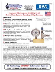
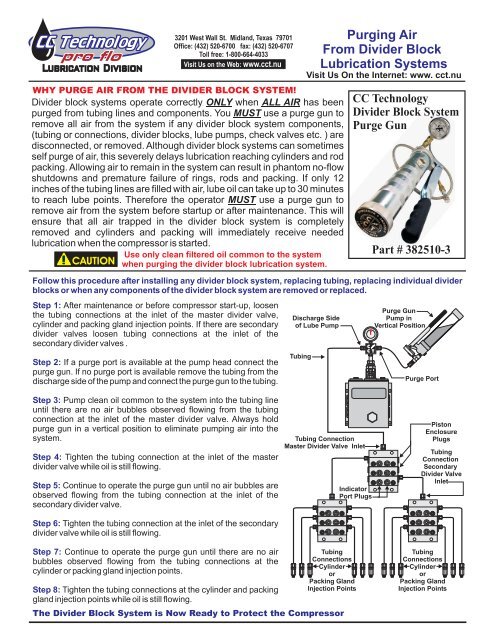
3201 West Wall St. Midland, Texas 79701Office: (432) 520-6700 fax: (432) 520-6707Toll free: 1-800-664-4033Visit Us on the Web: www.cct.nu"PROTECTING COMPRESSORS WORLD WIDE"WHY PURGE AIR FROM THE DIVIDER BLOCK SYSTEM!Divider block systems operate correctly ONLY when ALL AIR has beenpurged from tubing lines and components. You MUST use a purge gun toremove all air from the system if any divider block system components,(tubing or connections, divider blocks, lube pumps, check valves etc. ) aredisconnected, or removed. Although divider block systems can sometimesself purge of air, this severely delays lubrication reaching cylinders and rodpacking. Allowing air to remain in the system can result in phantom no-flowshutdowns and premature failure of rings, rods and packing. If only 12inches of the tubing lines are filled with air, lube oil can take up to 30 minutesto reach lube points. Therefore the operator MUST use a purge gun toremove air from the system before startup or after maintenance. This willensure that all air trapped in the divider block system is completelyremoved and cylinders and packing will immediately receive neededlubrication when the compressor is started.Use only clean filtered oil common to the system! CAUTION when purging the divider block lubrication system.Discharge Sideof Lube PumpTubingPurging AirFrom Divider Block<strong>Lubrication</strong> SystemsFollow this procedure after installing any divider block system, replacing tubing, replacing individual dividerblocks or when any components of the divider block system are removed or replaced.Step 1: After maintenance or before compressor start-up, loosenthe tubing connections at the inlet of the master divider valve,cylinder and packing gland injection points. If there are secondarydivider valves loosen tubing connections at the inlet of thesecondary divider valves .Step 2: If a purge port is available at the pump head connect thepurge gun. If no purge port is available remove the tubing from thedischarge side of the pump and connect the purge gun to the tubing.Visit Us On the Internet: www. cct.nu<strong>CC</strong> <strong>Technology</strong>Divider Block System<strong>Purge</strong> <strong>Gun</strong>10005001500Part # 382510-32000<strong>CC</strong> T<strong>Purge</strong> <strong>Gun</strong>Pump inVertical Position25003000<strong>Purge</strong> PortStep 3: Pump clean oil common to the system into the tubing lineuntil there are no air bubbles observed flowing from the tubingconnection at the inlet of the master divider valve. Always holdpurge gun in a vertical position to eliminate pumping air into thesystem.Step 4: Tighten the tubing connection at the inlet of the masterdivider valve while oil is still flowing.Step 5: Continue to operate the purge gun until no air bubbles areobserved flowing from the tubing connection at the inlet of thesecondary divider valve.Tubing ConnectionMaster Divider Valve InletIndicatorPort PlugsPistonEnclosurePlugsTubingConnectionSecondaryDivider ValveInletStep 6: Tighten the tubing connection at the inlet of the secondarydivider valve while oil is still flowing.Step 7: Continue to operate the purge gun until there are no airbubbles observed flowing from the tubing connections at thecylinder or packing gland injection points.TubingConnectionsCylinderorPacking GlandInjection PointsStep 8: Tighten the tubing connections at the cylinder and packinggland injection points while oil is still flowing.The Divider Block System is Now Ready to Protect the CompressorTubingConnectionsCylinderorPacking GlandInjection Points
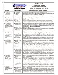
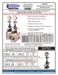
3201 West Wall St. Midland, Texas 79701C. C. <strong>Technology</strong> Inc.Office: (432) 520-6700 fax: (432) 520-6707Heavy Duty Lever Action <strong>Purge</strong> and Test <strong>Gun</strong>with Chrome Plated Steel Reservoir0-5000 PSI Stainless SteelLiquid Filled Pressure GaugeToll free: 1-800-664-4033Visit Us on the Web: www.cct.nu“Protecting Compressors World Wide”Internal & External7500# S.S. Check ValveRubber Grip HandleBulletin PG11-06LEVER ACTIONPURGE & TEST GUNMODEL# 382510-3Liquid LevelSight GlassChrome PlatedSteel ReservoirTEST CHECK VALVESPRE-LUBE CYLINDERS & PACKINGPRESSURE TEST DIVIDER BLOCKSREMOVE OBSTRUCTIONS FROM INJECTION POINTSREMOVE AIR FROM DIVIDER BLOCK SYSTEMSPRIOR TO COMPRESSOR START-UP36”Stainless Steel Braided Hose AssyWith S.S. Tubing ConnectionsDESCRIPTIONThe <strong>CC</strong>T purge gun provides a convenient, costeffective method to remove all air from the dividerblock system to ensure all lubrication points willreceive lubrication immediately on start-up of thecompressor. The manual pump is also an efficientdevice to trouble shoot the divider block system tolocate blockage in divider blocks, tubing lines, andcylinder/packing injection points. The pump deliversfull pressure at minimum stroke for ease of use intight quarters. All pumps are provided with a 36”stainless steel braided hose for long reachapplications, 5000 PSI stainless steel liquid filledpressure gauge and chrome plated steel tube withbulls eye sight glass.FEATURESHeavy duty cast aluminum alloy pump headPrecision fit, hardened plunger develops 5,000# pressureChrome plated steel reservoir.Visual level indication eliminates injecting air into the dividerblock system.Stainless steel liquid filled pressure gauge36” stainless steel braided hose with all tubing connectionsTROUBLESHOOTING GUIDEPROBLEM POSSIBLE CAUSE CORRECTIONPump fails to Develop PressureA. Vacuum created in tubeB. Debris holdingBall check openLoosen end cap to relieve vacuumRemove hose assy from gun head.Remove spring & ball. Clean partsthoroughly.