2100-113 - Bard Manufacturing Company
2100-113 - Bard Manufacturing Company
2100-113 - Bard Manufacturing Company
- No tags were found...

You also want an ePaper? Increase the reach of your titles
YUMPU automatically turns print PDFs into web optimized ePapers that Google loves.
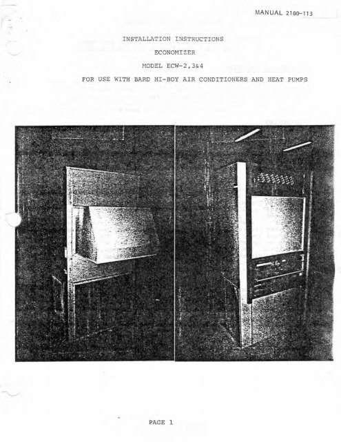
MANUAL <strong>2100</strong>-<strong>113</strong>INSTALLATION INSTRUCTIONSECONOMIZERMODEL ECW-2,3&4FOR USE WITH BARD HI-BOY AIR CONDITIONERS AND HEAT PUMPS-PAGE 1
INSTALLATION INSTRUCTIONSFORECONOMIZER MODELS ECW-2,3&4 FOR USE WITH BARDHIGH BOY AIR CONDITIONERS AND HEAT PUMPSGENERAL INFORMATION-.The economizer should only be installed by a trained heatingand air conditioning technician. These instructions serve as aguide to the technician installing the economizer package. Theyare not intended as a step by step procedure with which the mechanicallyinclined owner can install the package.UNPACKINGUpon receipt of the equipment, the cartons should be checkedfor external signs of shipping damage. If damage is found, thereceiving party must contact the last carrier immediately, preferablyin writing, requesting inspection by the carrier's agent.DESCRIPTIONThe ECW-2,3&4 economizers are designed to be used with <strong>Bard</strong>Hi-Boy series heat pumps and air conditioners. They are electricalmechanical economizer systems designed to provide "free" molingwhere the outdoor air temperature is cool enough to providethe needed cooling without running the compressor. When coolingis needed, the system automatically takes advantage of the coldoutdoor air when available and uses it for first stage cooling.This then reduces the need to run the air conditioning compressorproviding lower operating costs and increasing the service lifeof the equipment. If the outdoor air gets too warm or humid tobe helpful, the enthalpy control detects the condition and automaticallycloses the outdoor air damper and opens the return airdamper and switches to the compressor operation. This is alldone automatically to achieve maximum savings without attentionfrom the user.The economizer is shipped in one carton which contains theintake hood subassembly, return damper subassembly, damper crosslink, blower cover panel subassembly, electrical access paxrelsubassembly, miscellaneous screws and installation instructions.The exhaust air damper assembly is an option and is both orderedand shipped separately.d-PAGE 2
ECONOMIZERFactory Built - Field Installed For<strong>Bard</strong> Wall Mount Air Conditioners and Heat PumpsPRELIMINARY SPECIFICATIONSSTANDARD FEATURESPROPORTlONlNC TYPE CONTROL for maximum "Freacodingn economy and comfort with up to ?DO8 outdoorNew DAMPER ACTUATOR MOTOR wlth spring return.Law currant draw - diminmttr nacd to clung. to largerair.14 volt transformer.PLEATED A[ R FILTER to provide rnnxlmum filtration of CASKETED DAMPERS for minimum air lukage. Thisboisidaraves energy by mlnlmiling outside mIr Iwkage into theSIT.unit when the dampers are dosd.MOfSTURE ELIMINATOR AND PRE-FILTER - permanmt,washable rIuminum construclbn.EASY TO SERVICEADJUSTABLE LOW TEMPERATURE COMPRESSOR CUTOFF0and sarvice.rrnbicnt control.ENf HALW CONTROL ta mOnItor outdoor temperature andhumidity - mdjuslrble.MINIMUM POSITION POTENTIOMETER - adjustrble toconrrd minimum damper blade position.Ecmomlrer controls - usily acces~ibl+ far adjustment*Basic rlr condilloner mnd hdt pump unit controlsand compresror rtmmin unobstructid and accessible.2 STAGE COOLING THERMOSTAT\-MIXED AIR SENSOR to monitor outdoor and return air torurormtically mrdula te damper position.*~UC-IN~servrce.OPTIONAL FEATURESWIRING HARNESS for easy Installation and EXHAUST AIR DAMPER ASSEMBLY - damper assembly -field installed; provides txhmust air capability to preventprtssurtzation of tlght butldings.
DIMENSIONSrAlSERVICE DOORDnlnEWER AIRFLOWLOW THROUGH1IMi HAETURH AIRINSTALLEDFROHf VI€W 510E VlEW BACK VlEWBASIC MODEL2WIA.231YA.lOWH,lWHA32413i69i20820+12H*9I*12,*6416;15t16k-20;- P11:MoistureEliminator~ f I#+ x00AirFitter10x2530YIA,36WA,30WH,36WH38415474280181412128119:17I8!23419124 x 2316x25P~WA. 4MA.48WJ-I421289301030167+11716:2ri<strong>113</strong>1;19fttx32i16x34Dimensions 8nd filtar.sizer art In inches.*Optinnel: For axbust air damper assembly.SEQUENCE OF OPERATION'CONDITION A - COOL OUTDOORS1st stage cmlIng closes and powers the aeonomizardampers to ~onairer mods and the Indmr blower1t8rtl. Mixed Air Sm~lr (thermistor) sanses 8 mixtureof return alr mnd wrtdmr mir and wdulates thedampars accordingly. Compresror operation Is inhibited.lr s.cond sum closes on the th.rsmstnt. the dampersraturn to thm dosed or mlnlrnum positicm settlng and thecmpraswr starts for mcchmniul dlng.Compnswr Idout thermosut Is factory0. D. temperature [mdJustmble).CONDlf ION B - WARM OUTDOORSsat mt SOmF1st stage cding cycle^ the compresmr and dampersrtnwin In the machaniul coding mode.WALL THERMOSTATSThermostat, Part No. 8103-021For (Honeywdi T17401009)Alr Condi tionlng Subbase. Part No. 8009-01 2(Hontywdl Q674AlOOI)2 Stage Cod12 Suge HemtThermstat, Part No. 4403-023For (Honeywelt T83008 1027)Heat Pumps Subbase, Part No. 8103-015(Honeywell 463008 1000)Low Ambient. Control, #LAC-1Relay 18201-001Electronic H-I Pump fharmostmt2 Stage Cool12 Stay HeatORDERING INFORMATIONBasic AIC or HIPHdmlEconomizerPackageOpti0~l ExhaustDampar AssemblySpaclfirations subject tochange without notice.ZWA, 24WA. 18WH. ZYWHECW-2ED-230WA. 36WA. 30WH, 36WHIIWA, WWA, 46WH8Ag~ECW-3ED- 3-ECW-IED-PMANUFACTURING COMPANYw..-.*IC. yst4BRYAN. M O 43SM
BASIC INSTALLATION.-> 1. Unpack the ec zer assembly which includes the outside airintake hood assertwly, blower cover panel, electrical accesspanel, return air damper assembly, damper cross Link rod andelectrical harness & miscellaneous screws.(SEE FIGURE 1)FIGURE - I2. Remove the existing exterior fan access and service accesspanels on the <strong>Bard</strong> High-Boy units.(sl ;URE 2 )3. R~TIIUV~ a discard existing unit retu~ll air filter.NOTE: Economizer installation requires a field supplied andinstalled return air filter and filter grill. Freshair is filtered internally by econernbzer.PAGE 5- . . ~-
FIGURE - 24. Connect the mixed air thermistor sensor to the outside airintake hood assembly to position it in the air stream withthe screws and brackets provided.(SEE FIGURE 3)- JFIGURE 3PAGE 6
5. Attach the damper cross drive link rod to the ball swivel onthe fresh air intake damper and tighten securely.(SEE FIGURE 3)FIGURE - 46. Thread the leads of the female portion of the electrical harnessthru the bulkhead fitting of the compressor cover intothe electrical control panel portion of the Hi-Boy unit,Connect the numbered leads to the corresponding point in theunit terminal block. (SEE FIGURE 5 )FIGURE 5 PAGE 7
7. Install the new blower cover panel at top of unit with screws.Position the fresh air intake hood on the unit, Thread themale harness, mixed air sensor and the damper cross drive linkthru the unit between the fans. Take care not to bump thethermistor sensor. Secure the assembly to the unit with the -..,provided self drilling sheet metal screws thru the clearenceholes in the side flanges. (SEE FIGURE 6)FIGURE - 68. Connect the male and female portions of the harness togetherby reaching thru the opening in the unit under the hood.(SEE FIGURE 7)PAGE 8
FIGURE - 7-9. Install the return air damper in t rle L~LULII air opening of the<strong>Bard</strong> unit and secure w ith sheet metal screws thru the sideflanges of the return air duct collar into the damper frame.The damper frame should be flush with the edge of the collar.{SEE FIGURE 8)PAGE 9
10, Attach the damper cross link to the vacant ball swivel on thereturn air damper drive bracket so that the return air damperis fully cpen when the unit is off. (ie) The outside airdamper is Sully closed. (SEE FIGURE 9 j. ..FIGURE - 9El. Install the old interior electrical cover panel and new electricalaccess panel on <strong>Bard</strong> unit with screws.(SEE FIGURES 10 & 11)--FIGURE - 10
FIGURE - 1112. Wire the thermostat and subbase as shown on the diagram.(SEE SCHEHATICS PAGE JZCL3)13a. Remove the field adjustment economizer control access panelon the side of the outside air intake hood assembly. (SEEFIGURE 12.) Adjust'enthalpy control at maximum combinationof temperature and humidity considered acceptable for theinstallation as per chart by turning knob to A,B,C,or D.(SEE CHART f & 11)b. Set compressor lockout control thermostat to 5O0F by adjustingthe knob on the bimetal thermostat. This will inhibit the compressorfrom running in outdoor ambient temperatures below 50°to prevent the possibility of freezina the indoox mil.c. Adjust minimum position potentiometer to insure proper amountof fresh air intake to meet local codes or installation criteriawith screw driver. (SEE FIGURE 13)14. Replace economizer control access cover and secure with screws.15, Caulk all exterior seams to insure weather tig& integrity.(SEE FIGURE 14)Unitnow ready for operation.PAGE II
PAGE 14CHART I
CHART I II5 tJ 100 105 110.PARTIAL PSYCHROMETRIC CHART WITH PERFORMANCE CURVES SUPERIMPOSED. SHADEDAREA REPRESENTS CON1 ROC RANGE. CUA&S ILLUSTRATE RESET IN TEMPERATURE CONTROL#)I NT OUE TO CHANGES IN RELATIVE HUM1DlTY.PAGE 15
FIGURE 12 FIGURE 14FIGURE 13 PAGE 16
FILTER SERVICEL'A l l <strong>Bard</strong> Hi-Boy economizers come equipped with dual filtration.Primary filtration and mist elimination is accomplished by a 1"thickpermanent washable aluminum pre-f ilter . Secondary filtration isprovided by a throw-a-way 1" thick pleated cartridge filter. Accessfor removal, cleaning and replacement of this filter is thruthe bottom front of the intake hood subassembly. Remove the screwson the sides of the filter lower panel of the hood. (SEE FIGURE 15.)Remove the filter lower panel and slide the filters out of theirracks for cleaning and replacement. (SEE FIGURE 16.)Replacement cartriges are available from your <strong>Bard</strong> dealer and aresized as follows:- UNIT NOMINAL FILTER DIMENSIONSReplace tllters In their respective racks taking care to placethem corresponding to air flow and with the drain holes of the moistureeliminator at the lower end of the rack. Replace the filtercover panel and secure with screws.FIGURE - 15PAGE 17
FIGURE 16DAMPER MOTOR SERVICEAccess for service or replacementof the damper motor can be achievedby removing the front filter paneland filters {SEE FILTER SERVICE, 1This exposes all the control componentsin the intake hood assembly.Drive linkage adjustments can alsobe made in this manner.(SEE FIGURE 171PAGE 18-
RELIEF DAMPER'LlMany buildings have enough natural relief to avoid severeproblems with building and over-pressurization. In some installations,where large quantities of outdoor air is brought into atightly constructed building, exhaust provisions may be requiredto prevent over-pressurization. This can be accomplished by (a)nnatural" relief, [b) barometric relief dampers of (c) exhaustdampers. The need must be determined and if required, the properselection must be made for the application by the HVAC system designer.A fully integrated exhaust damper system is availableas as extra cost option. (.SEE SPECIFICATION SHEET.) .Cantactyour dealer for details.CHECKOUTWhen installation is complete, check the entire system forproper operation. The checkout procedure is intended to ensure:I. The economizer controls operate properly.2. The motor operates properly.3. The dampers perform as intended without binding.Set the enthalpy controller at maximum. Outdoor air dampershould open and return air damper should close.,When the setting of the enthalpy controller is turned to the1 -. other end of its range, the outdoor air damper should close tominimum position and the return air damper should open.Before leaving the installation, be sure to return all controllersto their recommended settings,-PAGE 19
PARTS LETECW-2, ECW-3, ECW-4ECONOMJ ZERPart No.DescriptionIECW-2ECW-3ECW-418201-01 50201-0138602- 002-8602- 0 1 78602-0188602-019 .7004- 0207004- 02 17004-022 -7002- 0057002-0067002- 007RelayRelayEnthalpy ControlEconomizer MotorThermistor SensorMinimum Position Potentiometerm iFilter 16x25~1Filter 16x 34% 1Moisture Eliminator 8-718x 24)x 1Moisture Eliminator 12tx29x1Moistuve Eliminator 124 x 324x 1axxxxxxxxxxxxxxx --Page 20