M-Series Model USTDII Digital Transmitter ... - MTS Sensors
M-Series Model USTDII Digital Transmitter ... - MTS Sensors
M-Series Model USTDII Digital Transmitter ... - MTS Sensors
- No tags were found...

You also want an ePaper? Increase the reach of your titles
YUMPU automatically turns print PDFs into web optimized ePapers that Google loves.
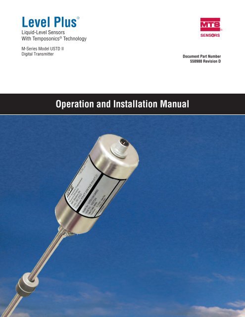
United StatesGeneral:Tel: +1-919-677-0100Fax: +1-919-677-2343E-mail: sensorsinfo@mts.comhttp://www.mtssensors.comMailing and Shipping Address:<strong>MTS</strong> Systems Corporation<strong>Sensors</strong> Division3001 Sheldon DriveCary, North Carolina, 27513, USACustomer Service:Tel: +1-800-457-6620Fax: +1-800-498-4442E-mail: orders@mts.comTechnical Support and Applications:24 Hour Emergency Technical SupportTel: +1-800-633-7609e-mail: levelplus@mts.com<strong>Model</strong> USTD II Operation and Installation ManualContact InformationOffice Hours (EST):Monday - Thursday: 8:00 a.m. to 5:00 p.m.Friday: 8:00 a.m. to 4:00 p.m.Remittance Address:<strong>MTS</strong> Systems Corporation<strong>Sensors</strong> DivisionNW 5872P.O. Box 1450Minneapolis, MN, 55486-5872Quote and Contract Terms & Conditions:The parties expressly agree that the purchase and use of Material and/or Services from <strong>MTS</strong> <strong>Sensors</strong> Division are subject to <strong>MTS</strong>’ Termsand Conditions, in effect as of the date of this document, which arelocated at http://www.mtssensors.com/fileadmin/media/pdfs/Terms_and_Conditions.pdf and are incorporated by reference into this andany ensuing contract. Printed Terms and Conditions can be providedupon request by emailing sensorsinfo@mts.com or if you prefer, go tohttp://www.mtssensors.com/index and click the Quote/Contract Termsand Conditions link at the bottom of the page to download the PDF.ContactInformationGermanyGeneral:Tel.: +49-2351-9587-0Fax: +49-2351-56491e-mail: info@mtssensor.dehttp://www.mtssensor.deMailing and Shipping Address:<strong>MTS</strong> Sensor Technologie, GmbH & Co. KGAuf dem Schüffel 9D - 58513 Lüdenscheid, GermanyTechnical Support and Applications:Tel.: +49-2351-9587-0e-mail: info@mtssensor.dehttp://www.mtssensor.deJapanGeneral:Tel.: +81-42-775-3838Fax: +81-42-775-5516e-mail: info@mtssensor.co.jphttp://www.mtssensor.co.jpMailing and Shipping Address:<strong>MTS</strong> <strong>Sensors</strong> Technology Corporation737 Aihara-cho, Machida-shiTokyo 194-0211, JapanTechnical Support and Applications:Tel.: +81-42-775-3838Fax: +81-42-775-5512<strong>MTS</strong> <strong>Sensors</strong>iLevel Plus ® Liquid-Level <strong>Sensors</strong> M-<strong>Series</strong> <strong>Model</strong> USTD II <strong>Digital</strong> <strong>Transmitter</strong>Operation and Installation Manual, Document Number 550980 Revision D, 03/12
<strong>Model</strong> USTD II Operation and Installation ManualReference InformationNotices used in this manualThis manual contains notices to highlight specific information as follows:Notes:These notices provide important tips, guidance, or advice.Important:ReferenceInformationThese notices provide information that might help you avoid inconvenient or problem situations.Attention:These notices indicate possible damage to programs, devices, or data and is placed justbefore the instruction or situation in which damage could occur.Caution:These notices indicate situations that can be potentially hazardous to you. A Caution notice is placed justbefore a description of a potentially hazardous procedure, step, or situation.Related publicationsThe following publications are listed below by part number followed by description and are availablein Adobe Acrobat Portable Document Format (PDF) at http://www.mtssensors.com/550949 - Product Specification, Level Plus USTD II551103 - Level Plus Accessories CatalogFor information about safe work procedures, refer to the following documentation:National Electric Code ANSI/NFPA 70CSA C22.1 Canadian Electrical CodeHow this manual is organized“Introduction”, provides an overview of the manual.“Terms and Definitions”, provides definitions of terms used in this manual.“Product Overview”, gives an overall product description for the Level Plus liquid-level transmitter, its specifications, use, output,and electronics.“Installation and Mounting”, provides detailed installation and mounting information.“Electrical Connections and Wiring Procedures”, provides engineering specifications and wiring diagrams to assist in the installationprocess.“Maintenance and Field Service”, provides guidelines for general maintenance and procedures for replacing the <strong>Model</strong> USTD II leveltransmitter.“Troubleshooting”, provides a list of symptoms, their possible cause and the action to be taken when troubleshooting the transmitter.“Quick Start-Up Guide”, provides a list of steps to quickly set up your USTD II.“DDA Protocol”, provides the DDA hardware and software environment overviews.“Agency Information” provides comprehensive listings of agency approvals and standards, installation drawings, labels and applicableprotocols.Getting information, help, and serviceYou can get the latest ordering information and software updates by visiting www.mtssensors.com websiteGeneral contact information, shipping and office hours are available on page i.Level Plus ® Liquid-Level <strong>Sensors</strong> M-<strong>Series</strong> <strong>Model</strong> USTD II <strong>Digital</strong> <strong>Transmitter</strong>Operation and Installation Manual, Document Number 550980 Revision D, 03/12ii<strong>MTS</strong> <strong>Sensors</strong>
<strong>Model</strong> USTD II Operation and Installation ManualProduct Overview<strong>Model</strong> number identification for ATEX approval<strong>Transmitter</strong> <strong>Model</strong> = U S T D I I 1 - 6MUM-<strong>Series</strong> <strong>Model</strong> USTD II liquid-level transmitterUnit of Measure = 7= Metric (millimeters)= US Customary (inches)<strong>Transmitter</strong> Order Length = 8 - 11LengthCodeMillimeters = XXXX (737 mm to 3785 mm)Inches= 0XXX (29 in. to 149 in.)mounting AND cATEGORY OF aPPARATUS = 12H = Fill tube mounting (hanger with centering spacers) FM ApprovedA = Flange mounting (¾ in. MNPT adjustable fitting) FM Approved6 = Flange mounting (¾ in. MNPT adjustable fitting) ATEX ApprovedmOUNTING TYPE = 13S = Standard product without cable (FM Approved)9 = Standard product without cable (ATEX Approved)7 = Cable gland and integral blue cable (ATEX Approved)sTANDARD fEATURESFive DT's, evenly spacedData output format (USTD type)USTD II cABLE aSSEMBLY oPTIONDescriptionPart number5 m straight connector cable (ATEX) 4024862 m straight connector cable (FM) 5300492 m 90° connector cable (FM) 370481ProductOverview<strong>MTS</strong> <strong>Sensors</strong>6Level Plus ® Liquid-Level <strong>Sensors</strong> M-<strong>Series</strong> <strong>Model</strong> USTD II <strong>Digital</strong> <strong>Transmitter</strong>Operation and Installation Manual, Document Number 550980 Revision D, 03/12
<strong>Model</strong> USTD II Operation and Installation ManualProduct OverviewProduct specificationsProductOverviewParametersLEVEL OUTPUTMeasuredvariable:Output signal /Protocol:Order length:SpecificationsProduct level and interface levelDDA/USTDRigid pipe: 737 mm (29 in.) to3785 mm (149 in.) §∆§ Order length equals the distance from the bottomof the housing to the tip of the pipe, (includingthe inactive zone).∆ Contact factory for longer lengths.Non-linearity: ± 0.5 mm (0.02 in.)Repeatability: 0.001% F.S. or 0.381 mm (0.015 in.)◊◊ Whichever is greater.Temperature OutputMeasuredvariable:Accuracy:electronicsInput voltage:Fail safe:Reverse polarityprotection:Lightning/Transientprotection:calibrationZero adjustrange:Span adjustrange:Average and multipoint temperaturesUp to 5± 0.28 °C (± 0.5 °F)10.5 to 30.1 Vdc28 Vdc maximum for I.S. ATEX approvalHigh, Full scale<strong>Series</strong> diodeStage 1:Line-to-ground surge suppression;IEC 61000-4-5Stage 2:Line-to-line and line-to-ground transientsuppressors; IEC 61000-4-4Anywhere within the active lengthFull scale to 152 mm (6 in.) from zeroParameters SpecificationsenvironmentalEnclosure rating: IP 68Humidity: 0 to 100% relative humidity,noncondensingOperatingtemperatures:Electronics:-40 °C (-40 °F) to 71 °C (160 °F)Sensing element:-40 °C (-40 °F) to 125 °C (257 °F)Temperature element:-40 °C (-40 °F) to 105 °C (221 °F)Vessel pressure: 4 bar (60 psi)Materials: Wetted parts: 316L stainless steelNon wetted parts: 316L stainless steelfield installationHousingdimensions:Mounting:Wiring:ElectricalConnections:51 mm (2 in.) dia. by132 mm (5.2 in.) height¾ in. Adjustable NPT fitting (ATEX, FM) orFill tube hanger (FM only)4-wire, plus earth ground5-pin M12 connectorLevel Plus ® Liquid-Level <strong>Sensors</strong> M-<strong>Series</strong> <strong>Model</strong> USTD II <strong>Digital</strong> <strong>Transmitter</strong>Operation and Installation Manual, Document Number 550980 Revision D, 03/12 7<strong>MTS</strong> <strong>Sensors</strong>
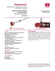
Installation &Mounting<strong>Model</strong> USTD II Operation and Installation ManualInstallation & MountingMountingThe method of mounting a Level Plus M-<strong>Series</strong> transmitter is dependent on the vessel or tank in which it is being used and what type oftransmitter is being used. There are two typical methods for mounting, internal and external.External mount<strong>MTS</strong> offers the Level Plus <strong>Model</strong> USTD II transmitter configured with a rigid pipe constructed of 316L stainless steel. The rigidpipe configuration can be ordered in lengths from 737 mm (29 in.) to 3785 mm (149 in.). The <strong>Model</strong> USTD II can be installed usinga flange mount (see illustration below). The flange mount allows the transmitter to be installed external to the tank througha flange with a ¾ in. MNPT Adjustable fitting which is FM and ATEX approved. The NPT fitting allows the transmitter mount to be adjusted(within an inch) if the tank height and order length are not exactly equal.The ‘Measuring range’ of the <strong>Model</strong> USTD II transmitter is equal to the ‘Order length’ minus the ‘Mounting zone’ at 51 mm (2.0 in.) and the‘Inactive zone’ of 32 mm (1.25 in.). The <strong>Model</strong> USTD II transmitter can be ordered with a single product float or can include the optionalinterface float (Refer to page 33 for float specifications). Average and individual temperature measurement from five positions are included.Figure 3. External mounting exampleLevel Plus ® Liquid-Level <strong>Sensors</strong> M-<strong>Series</strong> <strong>Model</strong> USTD II <strong>Digital</strong> <strong>Transmitter</strong>Operation and Installation Manual, Document Number 550980 Revision D, 03/12 9<strong>MTS</strong> <strong>Sensors</strong>
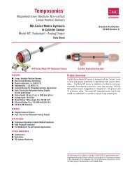
<strong>Model</strong> USTD II Operation and Installation ManualInstallation & MountingInternal mount<strong>MTS</strong> offers the Level Plus <strong>Model</strong> USTD II transmitter configured with a rigid pipe constructed of 316L stainless steel. The rigid pipe configurationcan be ordered in lengths from 737 mm (29 in.) to 3785 mm (149 in.). The <strong>Model</strong> USTD II can be installed using a Fill Tube Hanger mount(see illustration below). The fill tube hanger mount allows the transmitter to be installed in the fill tube or riser pipe within the tank and is FMapproved.The ‘Measuring range’ of the <strong>Model</strong> USTD II transmitter is equal to the ‘Order length’ minus the ‘Inactive zone’ of 32 mm (1.25 in.). The overalllength of the transmitter in the tank is equal to the ‘Order length’ plus the height of the housing and bracket at 176.5 mm (6.95 in.) The <strong>Model</strong>USTD II transmitter can be ordered with a single product float, or can include the optional interface float. Average and individual temperaturemeasurement from five positions are included.** The fill tube hanger mount is not available with ATEX approval101.6 mm(4 in.) dia.USTD IIO.D.51 mm(2 in.)(Customer supplied)38 mm (1.49 in.)Fill tube hanger176.5 mm(6.95 in.)SpacerSpacer width98.3 mm (3.87 in.)Measuring rangeStainless-steelRigid pipeOrder length737 mm (29 in.) to3785 mm (149 in.)Figure 4. Internal mounting exampleInactive Zone32 mm (1.25 in.)Installation &Mounting<strong>MTS</strong> <strong>Sensors</strong>10Level Plus ® Liquid-Level <strong>Sensors</strong> M-<strong>Series</strong> <strong>Model</strong> USTD II <strong>Digital</strong> <strong>Transmitter</strong>Operation and Installation Manual, Document Number 550980 Revision D, 03/12
<strong>Model</strong> USTD II Operation and Installation ManualInstallation & MountingElectrical connections and wiring proceduresA typical intrinsically safe connection for the Level Plus M-<strong>Series</strong> transmitter includes protective safety barriers, a power supply and a readingor monitoring device. Refer to Agency information for detailed information.Safety recommendations for installationAlways follow applicable local and national electrical codes and observe polarity when making electrical connections. Never make electricalconnections to the M-<strong>Series</strong> transmitter with power turned on. Make sure that no wire strands are loose or sticking out of the terminal blockconnection which could short and cause a problem. Make sure that no wire strands, including shield, are in contact with the electronicmodule enclosure. The electronics module enclosure is grounded through internal circuitry and electrically isolated from the explosion-proofenclosure.Industrial topologiesThere are four topologies described and illustrated below. However, the daisy chain topology is not recommended by <strong>MTS</strong>.Point-to-pointThe point-to-point topology consists of having only one device onthe loop as shown in Figure 5. This topology is not usually usedwith a bus network since it does not take advantage of placingmultiple devices on a loop.PLCFigure 5. Point-to-point topologyBus with spursThe bus with spurs topology has a main trunk cable that has eachdevice connected via its own spur at a junction box as shown inFigure 6. The bus with spurs and tree topologies can also be usedtogether to form a hybrid topology.PLCFigure 6. Bus with spurs topologyTree alignmentThe tree topology is very similar to the bus with spurs topologywith the main difference of having a common junction box for allof the transmitters as shown in Figure 7. Bus with spurs and treetopologies can also be used together to form a hybrid topology.PLCInstallation &MountingDaisy chainThe daisy-chain topology utilizes a single cable that is connected toall of the transmitters with the cable being interconnected at eachfield device. When using this topology make sure that the wiringpractice allows for one transmitter to be disconnected withoutdisconnecting the entire loop as shown in Figure 8. <strong>MTS</strong> does notsuggest using the daisy-chain topology.Figure 7. Tree topologyPLCFigure 8. Daisy-chain topologyLevel Plus ® Liquid-Level <strong>Sensors</strong> M-<strong>Series</strong> <strong>Model</strong> USTD II <strong>Digital</strong> <strong>Transmitter</strong>Operation and Installation Manual, Document Number 550980 Revision D, 03/12 11<strong>MTS</strong> <strong>Sensors</strong>
Recommended cable typesListed below are general requirements of cable types for the Level Plus <strong>Model</strong> USTD II digital transmitter.Cable recommendation:• Shielded, twisted pair, 24 AWG or heavier• Minimum 85 °C temperature rating.• Minimum 0.010 in. (0.25 mm) insulation thickness• 30 picofarads/foot or less. (see Notes).<strong>Model</strong> USTD II Operation and Installation ManualElectrical Connections and WiringConnections &WiringNotes:1. The return conductor for the power supply circuit is connected to the shield at the safety barrier ground terminal. When determining the capacitance ofcable for the power supply circuit, use the manufacturer’s capacitance specifications shown for one conductor and the other conductor connected tothe shield.2. Most cable manufacturers do not list inductance properties for cables. Where the inductance properties are unavailable, ISA RP12.6 (Installation ofIntrinsically Safe Instrument Systems in Class I Hazardous Locations) recommends the use of 0.2 µH (micro henries) per foot as a value for cableinductance.3. Termination and biasing of RS-485 data lines are as follows:• Biasing - Each M-<strong>Series</strong> transmitter has internal high impedance biasing resistors (30K Ω) on both RS-485 data lines. Noadditional biasing resistors should be present on the connecting devices (PLC, DCS, PC, converter).• Termination - Each M-<strong>Series</strong> transmitter has an internal termination resistor (100K Ω) installed across the RS-485 signal lines.No additional termination resistors are necessary in the connecting devices (PLC, DCS, PC, converter).GroundingThe USTD II must have a dedicated earth ground connected to the housings’ ground lug. Refer to Agency information for more information.Safety barriersEntity ParameterFMATEXVmax =28 VdcImax = 200 mACi = 0µFLi = 0 mHUi = 28 VdcIi = 200 mACi = Negligibly lowLi = Negligibly lowSupplier Type Maximum voltage Maximum current Maximum power Maximum resistanceSTAHL 9001/01-280-165-101 28 Vdc 165 mA 1155 mW 198Ω 1STAHL 9001/01-280-110-101 28 Vdc 110 mA 770 mW 294Ω 1MTL 728 28 Vdc 93 mA 651 mW 300Ω 1MTL 728+ 28 Vdc 93 mA 651 mW 300Ω 1MTL 7028+ 28 Vdc 93 mA 651 mW 300Ω 1MTL 7128+ 28 Vdc 93 mA 651 mW 300Ω 1MTL 7728+ 28 Vdc 93 mA 651 mW 300Ω 1Table 2. Power supply (+24 Vdc)Supplier Type Maximum voltageMaximum current(each channel)Maximum power(each channel)Maximum resistance(each channel)STAHL 9001/01-086-010-101 8.6 Vdc 10 mA 21.5 mW 963Ω 1STAHL 9002/11-120-024-001 12 Vdc 12 mA 70 mW 1156Ω 2MTL 764+ 12 Vdc 24 mA 72 mW 1075Ω 2Table 3. Communication lines (TX/RX+ and TX/RX-)Number ofchannelsNumber ofchannels<strong>MTS</strong> <strong>Sensors</strong>12Level Plus ® Liquid-Level <strong>Sensors</strong> M-<strong>Series</strong> <strong>Model</strong> USTD II <strong>Digital</strong> <strong>Transmitter</strong>Operation and Installation Manual, Document Number 550980 Revision D, 03/12
Connections &Wiring<strong>Model</strong> USTD II Operation and Installation ManualMaintenance and Field ServiceMaintenance and field serviceThis section contains information about post installation maintenance and provides an overview of <strong>MTS</strong> <strong>Sensors</strong>’ repair and replacementprocedures.General maintenance and field service requirementsNotes:Please contact Technical Support or Customer Service for help when damage occurs in order to obtain a return materials authorization (RMA) number.Packages without a RMA number may be rejected. Any unit that was used in a process must be properly cleaned in accordance with OSHA standards,before it is returned to the factory. A Material Safety Data Sheet (MSDS) must accompany material that was used in any media.Float maintenanceLevel Plus M-<strong>Series</strong> transmitters use magnetostrictive technology and only have one moving part—the float. This technology ensures noscheduled maintenance or recalibration is required. However, <strong>MTS</strong> recommends that you check the transmitter pipe annually for build up ofprocess material. Floats should move freely along the pipe. If they do not, routine cleaning should be performed.Field serviceIf damage does occur to a M-<strong>Series</strong> transmitter, the transmitter can be serviced in the field with replacement parts. Please contact TechnicalSupport for detailed steps of field replacement.Service / RMA PolicyIf the customer suspects their transmitter is damaged or not functioning correctly, call <strong>MTS</strong> Technical Support for further instruction. If it isnecessary to return the transmitter to the factory, an RMA number is required and can only be issued by Technical Support. Product returnsthat do not include an RMA will be returned to the customer. <strong>MTS</strong> evaluates the transmitter and advises the customer whether a repair orreplacement is necessary and any cost that might be incurred. If the customer declines repair/replacement or the transmitter has no faultfound, the unit is sent back as is and the customer is charged with a standard evaluation fee.If the transmitter is under warranty and a manufacturer’s defect is detected, there will be no cost to the customer for repair or replacement. Ifthe transmitter is out of warranty or if the customer has damaged the transmitter, a repair or replacement quote will be provided. In specificcases where the transmitter can not be removed and returned to the factory for evaluation, field evaluations can be performed in the field byan <strong>MTS</strong> technician. If field evaluation must be performed, the customer is responsible for all expenses incurred for travel, evaluation, partsand repair time. However, if the transmitter is under warranty and the problem is due to a manufacturer’s defect, there is no cost to thecustomer for replacement parts. To discuss all service options, contact Technical Support.Level Plus ® Liquid-Level <strong>Sensors</strong> M-<strong>Series</strong> <strong>Model</strong> USTD II <strong>Digital</strong> <strong>Transmitter</strong>Operation and Installation Manual, Document Number 550980 Revision D, 03/12 13<strong>MTS</strong> <strong>Sensors</strong>
<strong>Model</strong> USTD II Operation and Installation ManualDDA User InterfaceUSTD II Command set tableCommand code (hex) and namePossible answersC0 01 “STX DDA ETX” 115FF 02“SOH {access code} EOT”“SOH a a a EOT”C0 0AOutput level 1 ( product ) at 0.1 inch resolutionC0 0BOutput level 1 ( product ) at 0.01 inch resolutionC0 0COutput level 1 ( product ) at 0.001 inch resolutionC0 10Output level 1 ( product ) and level 2 ( interface ) at 0.1inch resolutionC0 11Output level 1 ( product ) and level 2 ( interface ) at 0.01inch resolutionC0 12Output level 1 ( product ) and level 2 ( interface ) at0.001 inch resolutionC0 19Average temperature at 1 degree Fahrenheit resolutionC0 1AAverage temperature at 0.1 degree Fahrenheit resolutionC0 1BAverage temperature at 0.01 degree FahrenheitC0 1FAverage and individual DT temperature at 1 degreeFahrenheit resolutionC0 20Average and individual DT temperature at 0.1 degreeFahrenheit resolutionC0 21Average and individual DT temperature at 0.01 degreeFahrenheit resolution“STX a a a ETX” or no response“ACK” or no responseTMAXin ms115800C0 0A “STX d d d d . d ETX”C0 0A “STX E 1 0 2 ETX” 800C0 0B “STX d d d d . d d ETX”C0 0B “STX E 1 0 2 ETX” 800C0 0C “STX d d d d . d d d ETX”C0 0C “STX E 1 0 2 ETX” 800co 10 “STX d d d d . d : d d d d . d ETX”C0 10 “STX E 1 0 2 : E 1 0 2 ETX” 800C0 11 “STX d d d d . d d : d d d d . d d ETX”C0 11 “STX E 1 0 2 : E 1 0 2 ETX” 800C0 12 “STX d d d d . d d d : d d d d . d d d ETX”C0 12 “STX E 1 0 2 : E 1 0 2 ETX” 800C0 19 “STX d d d d ETX”C0 19 “STX E 2 0 1 ETX” 800C0 1A “STX d d d d . d ETX”C0 1A “STX E 2 0 1 ETX”C0 1A “STX E 2 12 ETX” 800C0 1B “STX d d d d . d d ETX”C0 1B “STX E 2 0 1 ETX” 800C0 1F “STX d d d d : d d d d : ... : d d d d ETX”C0 1F “STX E 2 0 1 : d d d d : ... : d d d d ETX”C0 1F “STX E 2 12 : d d d d : ... : d d d d ETX” 800C0 20 “STX d d d d . d : d d d d . d : ... : d d d d . d ETX”C0 20 “STX E 2 0 1 : d d d d . d : ... : d d d d . d ETX”C0 20 “STX E 2 12 : d d d d . d : ... : d d d d . d ETX” 800C0 21 “STX d d d d . d d : d d d d . d d : ... : d d d d . d d ETX”C0 21 “STX E 2 0 1 : d d d d . d d : ... : d d d d . d d ETX”C0 21 “STX E 2 12 : d d d d . d d : ... : d d d d . d d ETX” 800C0 4DRead level offset data C0 4D “STX d d d d . d d d : d d d d . d d d ETX” 115C0 4FRead device infoC0 4F “STX O . N . = {ordering number} : F . N . = {factorynumber} : A . C . = {access code} : V 3 . 08_ETX” 115C0 57“SOH c : d d d d . d d d EOT”Set offset for float c C0 57 “STX c : d d d d . d d d ETX” 115DDA UserInterface<strong>MTS</strong> <strong>Sensors</strong>16Level Plus ® Liquid-Level <strong>Sensors</strong> M-<strong>Series</strong> <strong>Model</strong> USTD II <strong>Digital</strong> <strong>Transmitter</strong>Operation and Installation Manual, Document Number 550980 Revision D, 03/12
DDA UserInterface<strong>Model</strong> USTD II Operation and Installation ManualDDA User InterfaceNotes:C0 Gauge address byte possible range: C0 - FD** Includes ASCII stringsa a a Address in characters possible range: 192 - 255d d d d . d d d Numbers in characters supressed are: leading zeros and positive sign (+)(access code) Unique code, 10 ASCII characters (FN+serial number) example: 12345678(ordering number) See ordering documents, 14 ASCII characters example: <strong>USTDII</strong> - M256569(serial number) 8 ASCII characters example: 98010001USTD II error codesE102 Missing float A level request has been made with no level data returned.E212 DT communication error A DT is shorted or open or has been set to ‘not active’.E201 No DT’s programmed DT’s are not active or there are no DT’s.Level Plus ® Liquid-Level <strong>Sensors</strong> M-<strong>Series</strong> <strong>Model</strong> USTD II <strong>Digital</strong> <strong>Transmitter</strong>Operation and Installation Manual, Document Number 550980 Revision D, 03/12 17<strong>MTS</strong> <strong>Sensors</strong>
USTD II <strong>Digital</strong> setup software installation, setup and calibrationAdjustments to the calibration and set up parameters of the transmitter can be performed using the M-<strong>Series</strong> <strong>Digital</strong> Setup Software package.The software can be run from any PC using a RS-485 to RS-232 converter (see Table 10 <strong>MTS</strong> part number references). In the ‘<strong>MTS</strong> <strong>Digital</strong>Gauge Configuration - DDA - USTD II’ window, you will see one tab labeled ‘Data From Device’ (see Figure 9). You will use this tab and itsbutton selections to calibrate the transmitter and change setup parameters.Note:<strong>Model</strong> USTD II Operation and Installation ManualDDA User InterfaceYou must use a RS-485 converter with ‘Send Data Control’ when using the M-<strong>Series</strong> <strong>Digital</strong> Setup software to ensure proper operation.Example: B & B Electronics 485BAT3 (815-433-5100 www.bb-elec.com).Level Plus M-<strong>Series</strong> PC <strong>Digital</strong> Setup Software (DDA) CDRS-485 to RS-232 converterOrder number: 625053 Order number: 380075Table 10. <strong>MTS</strong> part number referencesData from device tabPerform the following steps to install the transmitter setup softwareto establish communications with the transmitter:1. Install Setup Software from the CD that came with yourtransmitter or go to www.mtssensors.com to download thelatest version.2. Connect transmitter to the RS-485 to RS-232 converter andattach the converter to your PC. Some PC’s will require anadditional Serial to USB converter.3. Open the Software program.4. Select COM Port. If you do not know which COM port toselect, right click My Computer and select Properties ->Hardware Tab -> Device Manager -> Ports (COM & LPT) toview the list.5. Click the ‘Data From Device’ tab, click the Device: pull-downand select the ‘transmitter address’, the factory default forDDA is 192 (see Figure 9).Parameter settings and calibration is performed from within theData From Device tab window (see Figure 9).DATA FROM DEVICE tab options:• Calibrate • Change Address • COM port• Adjust • Backup and restore device settingsCalibrationWhen you click the ‘Calibrate’ button in the ‘Data From Device’ tabwindow, the ‘Calibrate DDA Device’ window opens. There are twocalibration ‘Float Methods’ to choose from, From the drop downmenu select a calibration method. ‘Enter Float Positions (Calibrate)’and ‘Enter Float Zero Positions’. Click the ‘Offset Method:’ Select‘Enter Float Positions (Calibrate)’ and enter the current position ofthe float. Type a value in the active field, then click the ‘Send’ button.A confirmation window displays when the send is successful.Figure 10. Calibrate - Enter float positionsWhen you choose ‘Enter Float Zero Positions’ from the ‘OffsetMethod:’ drop down menu, you can adjust the offset where thetransmitters zero point is located. This adjustment will significantlyshorten the span of the transmitter or counter inactive zones. Adjustthe value accordingly and click ‘Send’. A confirmation windowdisplays when the send is successful.DDA UserInterfaceFigure 11. Calibrate - Enter float zero positionsFigure 9. Data from device tab<strong>MTS</strong> <strong>Sensors</strong>18Level Plus ® Liquid-Level <strong>Sensors</strong> M-<strong>Series</strong> <strong>Model</strong> USTD II <strong>Digital</strong> <strong>Transmitter</strong>Operation and Installation Manual, Document Number 550980 Revision D, 03/12
Agency approvalsIntrinsically SafeFM 3610EN 50020Class I, Division 1, Groups A, B, C and DType 4XPTB 04 ATEX 2107 X<strong>Model</strong> USTD II Operation and Installation ManualAgency InformationAgencyInformationGB3836.4-2000II 1/2 G bzw. II 2 GEEx ia IIB T4 bzw. EEx ia IIA T4Ex ia IIC T4<strong>MTS</strong> <strong>Sensors</strong>20Level Plus ® Liquid-Level <strong>Sensors</strong> M-<strong>Series</strong> <strong>Model</strong> USTD II <strong>Digital</strong> <strong>Transmitter</strong>Operation and Installation Manual, Document Number 550980 Revision D, 03/12
AgencyInformation<strong>Model</strong> USTD II <strong>Digital</strong> Operation and Installation ManualAgency InformationHazardous area installationFMFigure 16. USTD II installation drawingLevel Plus ® Liquid-Level <strong>Sensors</strong> M-<strong>Series</strong> <strong>Model</strong> USTD II <strong>Digital</strong> <strong>Transmitter</strong>Operation and Installation Manual, Document Number 550980 Revision D, 03/12 21<strong>MTS</strong> <strong>Sensors</strong>
Installation Drawing notes (FIGURE 16)Notes:<strong>Model</strong> USTD II <strong>Digital</strong> Operation and Installation ManualAgency Information1. Safety barriers are FMRC approved with entity parameters and must be used in an approvedconfiguration where the following conditions are met:• Voc, or Vt of the barrier combination is less than Vmax of the transmitter.• Isc, or It of the barrier combination is less than Imax of the transmitter.• Ca of the barrier combination is greater than the total Ci of the transmitters plus the cable capacitance.• La of the barrier combination is greater than the total Li of the transmitters plus the cable capacitance.• Total Li of the transmitters plus the cable capacitance.AgencyInformation<strong>Transmitter</strong> entity parameters:Vmax = 28 VdcImax = 200 mACi = 0 Li = 02. Power supply cable must be 24awg or heavier, shielded twisted pair cable. Cable capacitance must be less than 30pF per foot.Cable shield is connected to system ground at safety barrier end only. See installation manual for additional cable information.3. Communications cable must be 24 awg or heavier, shielded twisted pair cable. Cable capacitance must be less than 30pFper foot. Cable shield is connected to system ground at safety barrier end only. See installation manual for additional cableinformation.4. The wire connection between earth ground and the safety barrier ground terminal must be less than 1 ohm.5. Maximum approved number of DDA gauges for intrinsically safe wiring networks is 8. See operation and installationmanual for system configurations and restrictions.6. Connection to earth ground for transient protection circuitry.7. Ground screw provided to connect gauge housing to earth ground.8. The transducer frame shall be grounded to earth ground directly or through the equipment on which it is mounted and shall be at thesame potential as the safety barrier ground electrode.9. Electronic equipment connected to associated apparatus must not use or generate more than 250 volts RMS.10. Cable sets that are run together must have sufficient insulation to withstand 250 volts RMS between sets.11. All wiring must meet the requirements of the NEC and any local codes.Wiring connectionsOrangeRedGrayBlueBlackWiring diagramColorSignalRed24 Vdc PowerBlack0 Vdc PowerGrayEarth groundBlue TXD RXD +Orange TXD RXD -Figure 17. NEMA housing with connector<strong>MTS</strong> <strong>Sensors</strong>22Level Plus ® Liquid-Level <strong>Sensors</strong> M-<strong>Series</strong> <strong>Model</strong> USTD II <strong>Digital</strong> <strong>Transmitter</strong>Operation and Installation Manual, Document Number 550980 Revision D, 03/12
AgencyInformation<strong>Model</strong> USTD II <strong>Digital</strong> Operation and Installation ManualAgency InformationProduct Label<strong>Model</strong> No.: <strong>USTDII</strong> _ _ _ _ _ _ _ _Length: XXXIntrinsically SafeCL. I DIV 1 Gr. A,B,C,Dwhen connectedin accordance with FMapproved installation drwg.#650838Vmax: 28V, I max: 200 mA, Ci = 0μF Li = 0μHFigure 18. Label for model <strong>USTDII</strong>_ _ _ _ _HS, ASLevel Plus ® Liquid-Level <strong>Sensors</strong> M-<strong>Series</strong> <strong>Model</strong> USTD II <strong>Digital</strong> <strong>Transmitter</strong>Operation and Installation Manual, Document Number 550980 Revision D, 03/12 23<strong>MTS</strong> <strong>Sensors</strong>
ATEXNON HAZARDOUSLOCATION<strong>Model</strong> USTD II <strong>Digital</strong> Operation and Installation ManualAgency InformationHAZARDOUS LOCATION ( II 1/2 G bzw II 2 G EEx ia IIB T4 bzw EEx ia IIA` T4)AgencyInformationSAFETY24-26 Vdc +BARRIERSEE NOTE 10.22 mm 2 OR HEAVIERTWISTED PAIR CABLEWITH SHIELDSEE NOTE 2COMMON −EARTH GROUND(SEE NOTE 4)RX/TX +SAFETYBARRIERSEE NOTE 10.22 mm 2 OR HEAVIERTWISTED PAIR CABLEWITH SHIELDSEE NOTE 3RX/TX−SAFETYBARRIERSEE NOTE 1GROUNDEARTH GROUND(SEE NOTE 4)RX/TX−RX/TX+24 Vdc COMMON+24 VdcNON HAZARDOUSAREASEE NOTE 6TRANS. PROT.Figure 19. ATEX for DDA installation drawingTANKSIDEEARTHGROUND<strong>MTS</strong> <strong>Sensors</strong>24Level Plus ® Liquid-Level <strong>Sensors</strong> M-<strong>Series</strong> <strong>Model</strong> USTD II <strong>Digital</strong> <strong>Transmitter</strong>Operation and Installation Manual, Document Number 550980 Revision D, 03/12
AgencyInformation<strong>Model</strong> USTD II <strong>Digital</strong> Operation and Installation ManualAgency Informationinstallation drawing notes (Figure 19)Notes:1. Safety barriers are ATEX Certified with entity parameters and must be used in an approved configuration where the followingconditions are met:• Uo of the barrier combination is less than Ui of the transmitter.• Io of the barrier combination is less than Ii of the transmitter.• Co of the barrier combination is greater than the total Ci of the transmitters plus the cable capacitance.• Lo of the barrier combination is greater than the total Li of the transmitters plus the cable capacitance.<strong>Transmitter</strong> entity parameters:• Vmax = 28 Vdc• Imax = 200 mA• Ci = negligibly low• Li = negligibly low2. Power supply cable must be 0,22 mm 2 or heavier (e.g. 1.32 mm 2 AWG 16), shielded twisted pair cable. Cable capacitancemust be less than 160 pF/m. Cable shield is connected to system ground at safety barrier end only.3. Communications cable must be 0.22 mm 2 or heavier (e.g. 1.32 mm 2 AWG 16), shielded twisted pair cable. Cable capacitancemust be less than 160 pF/m. Cable shield is connected to system ground at safety barrier end only.4. The wire connection between earth ground and the safety barrier ground terminal must be less than 1 ohm.5. Maximum approved number of DDA or MODBUS gauges for intrinsically safe wiring networks is 6 to 8. Contact factory forModbus applications.6. Connection to earth ground for transient protection circuitry.7. Ground screw earthing hardware provided to connect gauge housing to earth ground.8. The transducer frame shall be grounded to earth ground directly or through the equipment on which it is mounted and shall be atthe same potential as the safety barrier ground electrode.9. Electronic equipment connected to associated apparatus must not use or generate more than 250 volts RMS.10. Cable sets that are run together must have sufficient insulation to withstand 250 volts RMS between sets.11. All wiring must meet the local regulations and/or other national/international standards.Wiring connectionsWhiteBlueGrayBrownBlackWiring diagramColorSignalBlue24 Vdc PowerBlack0 Vdc PowerGrayEarth groundBrown TXD RXD +White TXD RXD -Figure 20. NEMA housing with terminal strip or integral cableLevel Plus ® Liquid-Level <strong>Sensors</strong> M-<strong>Series</strong> <strong>Model</strong> USTD II <strong>Digital</strong> <strong>Transmitter</strong>Operation and Installation Manual, Document Number 550980 Revision D, 03/12 25<strong>MTS</strong> <strong>Sensors</strong>
Product Label®<strong>MTS</strong> SENSOR TECHNOLOGIEGmbH & Co. KGAuf dem Schüffel 9D-58513 LüdenscheidLevel Plus USTD II<strong>Model</strong> USTD II <strong>Digital</strong> Operation and Installation ManualAgency InformationAgencyInformation0102Type No.: <strong>USTDII</strong>XXXXXXSerial No.: XXXXXXXX/XX XXLength: XXXXXGradient: X.XXXX mS/in.Protection: IP67 (NEMA 4X)Agency MarkingPTB 04 ATEX 2107XII 1/2 G EEx ia IIB T4Um: 28 VIm: 200 mACi: 0µFLi: 0mFFigure 21. Label for <strong>USTDII</strong> _ _ _ _ _ 69, 67<strong>MTS</strong> <strong>Sensors</strong>26Level Plus ® Liquid-Level <strong>Sensors</strong> M-<strong>Series</strong> <strong>Model</strong> USTD II <strong>Digital</strong> <strong>Transmitter</strong>Operation and Installation Manual, Document Number 550980 Revision D, 03/12
AgencyInformation<strong>Model</strong> USTD II <strong>Digital</strong> Operation and Installation ManualAgency InformationNEPSI installation drawingFigure 22. NEPSI Installation drawingLevel Plus ® Liquid-Level <strong>Sensors</strong> M-<strong>Series</strong> <strong>Model</strong> USTD II <strong>Digital</strong> <strong>Transmitter</strong>Operation and Installation Manual, Document Number 550980 Revision D, 03/12 27<strong>MTS</strong> <strong>Sensors</strong>
Installation drawing notes (FIGURE 22)<strong>Model</strong> USTD II <strong>Digital</strong> Operation and Installation ManualAgency InformationAgencyInformationWIRING CONNECTIONS:Wiring diagramColorSignalRed24 Vdc PowerBlack0 Vdc PowerGrayEarth groundBlue TXD RXD +Orange TXD RXD -GrayOrangeBlueRedBlackFigure 23. NEPSI Wiring<strong>MTS</strong> <strong>Sensors</strong>28Level Plus ® Liquid-Level <strong>Sensors</strong> M-<strong>Series</strong> <strong>Model</strong> USTD II <strong>Digital</strong> <strong>Transmitter</strong>Operation and Installation Manual, Document Number 550980 Revision D, 03/12
AgencyInformation<strong>Model</strong> USTD II <strong>Digital</strong> Operation and Installation ManualAgency InformationProduct label5,070,485; 5,367,255; 5,334,933; 5,311,124; 5,587,680;5,848,549; 4,952,873; 5,545,984; 5,590,091; 5,736,855!Figure 24. NEPSI Product labelLevel Plus ® Liquid-Level <strong>Sensors</strong> M-<strong>Series</strong> <strong>Model</strong> USTD II <strong>Digital</strong> <strong>Transmitter</strong>Operation and Installation Manual, Document Number 550980 Revision D, 03/12 29<strong>MTS</strong> <strong>Sensors</strong>
<strong>Model</strong> USTD II Operation and Installation ManualAgency Information, FM ApprovalAgencyInformation<strong>MTS</strong> <strong>Sensors</strong>30Level Plus ® Liquid-Level <strong>Sensors</strong> M-<strong>Series</strong> <strong>Model</strong> USTD II <strong>Digital</strong> <strong>Transmitter</strong>Operation and Installation Manual, Document Number 550980 Revision D, 03/12
AgencyInformation<strong>Model</strong> USTD II Operation and Installation ManualAgency Information, FM ApprovalLevel Plus ® Liquid-Level <strong>Sensors</strong> M-<strong>Series</strong> <strong>Model</strong> USTD II <strong>Digital</strong> <strong>Transmitter</strong>Operation and Installation Manual, Document Number 550980 Revision D, 03/1231<strong>MTS</strong> <strong>Sensors</strong>
<strong>Model</strong> USTD II Operation and Installation ManualAgency Information, FM ApprovalAgencyInformation<strong>MTS</strong> <strong>Sensors</strong>32Level Plus ® Liquid-Level <strong>Sensors</strong> M-<strong>Series</strong> <strong>Model</strong> USTD II <strong>Digital</strong> <strong>Transmitter</strong>Operation and Installation Manual, Document Number 550980 Revision D, 03/12
AgencyInformation<strong>Model</strong> USTD II Operation and Installation ManualAgency Information, FM ApprovalLevel Plus ® Liquid-Level <strong>Sensors</strong> M-<strong>Series</strong> <strong>Model</strong> USTD II <strong>Digital</strong> <strong>Transmitter</strong>Operation and Installation Manual, Document Number 550980 Revision D, 03/1233<strong>MTS</strong> <strong>Sensors</strong>
<strong>Model</strong> USTD II <strong>Digital</strong> Operation and Installation ManualAgency Information, ATEX ApprovalAgencyInformation<strong>MTS</strong> <strong>Sensors</strong>34Level Plus ® Liquid-Level <strong>Sensors</strong> M-<strong>Series</strong> <strong>Model</strong> USTD II <strong>Digital</strong> <strong>Transmitter</strong>Operation and Installation Manual, Document Number 550980 Revision D, 03/12
AgencyInformation<strong>Model</strong> USTD II Operation and Installation ManualAgency Information, ATEX ApprovalLevel Plus ® Liquid-Level <strong>Sensors</strong> M-<strong>Series</strong> <strong>Model</strong> USTD II <strong>Digital</strong> <strong>Transmitter</strong>Operation and Installation Manual, Document Number 550980 Revision D, 03/12 35<strong>MTS</strong> <strong>Sensors</strong>
<strong>Model</strong> USTD II Operation and Installation ManualAgency Information, ATEX ApprovalAgencyInformation<strong>MTS</strong> <strong>Sensors</strong>36Level Plus ® Liquid-Level <strong>Sensors</strong> M-<strong>Series</strong> <strong>Model</strong> USTD II <strong>Digital</strong> <strong>Transmitter</strong>Operation and Installation Manual, Document Number 550980 Revision D, 03/12
AgencyInformation<strong>Model</strong> USTD II Operation and Installation ManualAgency Information, NEPSI EX ApprovalLevel Plus ® Liquid-Level <strong>Sensors</strong> M-<strong>Series</strong> <strong>Model</strong> USTD II <strong>Digital</strong> <strong>Transmitter</strong>Operation and Installation Manual, Document Number 550980 Revision D, 03/12 37<strong>MTS</strong> <strong>Sensors</strong>
Document Part Number: 550980 Revision D, 3/12<strong>MTS</strong>, Temposonics and Level Plus are registered trademarks of <strong>MTS</strong> Systems Corporation. All other trademarks are the property of their respective owners.Printed in USA. Copyright © 2012 <strong>MTS</strong> Systems Corporation. All Rights Reserved in all media.All specifications are subject to change. Contact <strong>MTS</strong> for specifications and engineering drawings that are critical to your application.Drawings contained in this document are for reference only. Go to http://www.mtssensors.com for the latest product information.SENSORS®<strong>MTS</strong> Systems Corporation<strong>Sensors</strong> Division3001 Sheldon DriveCary, North Carolina,27513, USATel.: +1-800-633-7609Fax: +1-919-677-2343+1-800-498-4442e-mail: sensorsinfo@mts.comhttp://www.mtssensors.com<strong>MTS</strong> Sensor TechnologieGmbH & Co. KGAuf dem Schüffel 9D - 58513 Lüdenscheid, GermanyTel.: +49-2351-9587-0Fax: +49-2351-56491e-mail: info@mtssensor.dehttp://www.mtssensor.de<strong>MTS</strong> <strong>Sensors</strong> TechnologyCorporation737 Aihara-cho, Machida-shiTokyo 194-0211, JapanTel.: +81-42-775-3838Fax: +81-42-775-5516e-mail: info@mtssensor.co.jphttp://www.mtssensor.co.jp