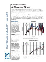
Introduction to Cyclic Corrosion Testing - Q-Lab
Introduction to Cyclic Corrosion Testing - Q-Lab
Introduction to Cyclic Corrosion Testing - Q-Lab

You also want an ePaper? Increase the reach of your titles
YUMPU automatically turns print PDFs into web optimized ePapers that Google loves.
Guidelines for CCT <strong>Testing</strong><br />
Because CCT tests are often complicated, multistep<br />
exposures, the procedures themselves can<br />
often confound the researcher. The following<br />
guidelines are intended <strong>to</strong> aid the user in understanding<br />
the possible sources of variability in CCT<br />
exposures. The guidelines are also intended <strong>to</strong><br />
assist in obtaining good inter-labora<strong>to</strong>ry agreement<br />
of results.<br />
Use of Reference Specimens<br />
Whenever possible, reference specimens (specimens<br />
of known performance in the test conducted)<br />
should be tested concurrently with the actual<br />
specimens under test. Preferably, more than one<br />
reference specimen will be used and the references<br />
chosen will bracket the test specimen’s expected<br />
performance. The references will allow the<br />
normalization of test conditions during repeated<br />
running of the test and will also guide comparisons<br />
of test results from different repeats of the test.<br />
Preparation of Test Specimens<br />
It is common practice <strong>to</strong> scribe or chip coated<br />
test samples before exposure <strong>to</strong> the CCT. This<br />
provides a break in the coating which accelerates<br />
corrosion. When a gravelometer is used, the procedure<br />
shown in D3170 13 is recommended.<br />
There is a growing body of evidence indicating<br />
that differences in scribe depth can significantly<br />
affect the CCT test results. This is particularly important<br />
for galvanized substrates. In most cases,<br />
the scribe should penetrate in<strong>to</strong> the base metal. It<br />
is especially important that the specific scribe <strong>to</strong>ol<br />
be reported, since scribe geometry can also affect<br />
results. A microscope may be useful for characterizing<br />
the scribe damage. A scribing method is<br />
described in ASTM D1654. 14<br />
Exposure Precautions<br />
In addition <strong>to</strong> the precautions specified in B117,<br />
the multi-functional nature of CCT exposures adds<br />
<strong>to</strong> the potential problems in the area of repeatability<br />
and reproducibility of results.<br />
Chamber Loading Level: Chambers that are<br />
loaded <strong>to</strong> capacity will normally take longer <strong>to</strong><br />
make transitions between temperatures than will<br />
lightly loaded chambers. Chambers should be<br />
loaded evenly <strong>to</strong> maintain good air flow during the<br />
test.<br />
Transition (Ramp) Time: Transition time can be<br />
a fac<strong>to</strong>r affecting results in both manual and au<strong>to</strong>mated<br />
exposures. In manual exposures, transition<br />
time is the time that it takes <strong>to</strong> move the test<br />
specimens from one environment or exposure<br />
condition <strong>to</strong> another. In au<strong>to</strong>mated chambers,<br />
transition time refers <strong>to</strong> the time it takes the machine<br />
<strong>to</strong> change the exposure conditions inside<br />
the chamber. Au<strong>to</strong>mated chambers can be expected<br />
<strong>to</strong> give more predictable and reproducible<br />
transitions than manual exposures. The effect of<br />
transition times on test results still needs <strong>to</strong> be<br />
studied further. Therefore, as much as is practical,<br />
transition times should be moni<strong>to</strong>red and reported.<br />
Transition time can be expected <strong>to</strong> vary, depending<br />
upon:<br />
• Variability in ambient conditions<br />
• Variability in manual operational procedures<br />
• Type of equipment used<br />
• Cabinet loading<br />
13. D 3170, Standard Test Method for Chip Resistance of Coatings.<br />
14. D 1654, Method for Evaluation of Painted or Coated Specimens Subjected <strong>to</strong> Corrosive Environments.<br />
Fog Deposition and Uniformity: In conventional<br />
salt spray tests, the uniformity of fog dispersion is<br />
typically determined by collecting the fog fall-out<br />
at various positions around the chamber. Unlike<br />
B117, moni<strong>to</strong>ring of CCT fog deposition rates cannot<br />
be accomplished while the test is operating.<br />
This is because most CCT exposures specify relatively<br />
short fog cycles. Consequently, <strong>to</strong> determine<br />
the fog dispersion uniformity in a CCT tester, it is<br />
necessary <strong>to</strong> collect the fog fall-out between tests<br />
in a special continuous spray run of at least 16<br />
hours. See section Method B117 for detailed instructions<br />
on fog collection.<br />
Test Interruptions: Whenever a test must be<br />
interrupted, the test panels should be s<strong>to</strong>red under<br />
the least corrosive conditions available. All<br />
interruptions and handling of panels should be<br />
reported.