Introduction to Cyclic Corrosion Testing - Q-Lab
Introduction to Cyclic Corrosion Testing - Q-Lab
Introduction to Cyclic Corrosion Testing - Q-Lab

Create successful ePaper yourself
Turn your PDF publications into a flip-book with our unique Google optimized e-Paper software.
TECHNICAL BULLETIN LF-8144.1<br />
<strong>Introduction</strong> <strong>to</strong><br />
<strong>Cyclic</strong> <strong>Corrosion</strong> <strong>Testing</strong><br />
This paper is intended as a general introduction <strong>to</strong> cyclic corrosion testing (CCT). It outlines the<br />
rationale for cyclic testing, includes some guidelines for using cyclic tests and explains some common<br />
CCT cycles and their applications. This discussion is not intended <strong>to</strong> be a complete, exhaustive<br />
tu<strong>to</strong>rial on cyclic corrosion testing. Consult the referenced technical papers for more detailed<br />
information.<br />
Background<br />
Salt spray was first used for corrosion testing<br />
around 1914. In 1939, the neutral salt spray<br />
test was incorporated as ASTM B117. 1 This<br />
traditional salt spray specifies a continuous<br />
exposure <strong>to</strong> a 5% salt fog at 35 o C. During the<br />
course of 80 years of use, there have been<br />
many modifications and refinements <strong>to</strong> B117.<br />
In spite of all these refinements, there has long<br />
been general agreement that “salt spray” test<br />
results do not correlate well with the corrosion<br />
seen in actual atmospheric exposures. Nevertheless,<br />
B117 has been generally accepted as<br />
the standard corrosion test method and is still<br />
widely specified for testing painted and plated<br />
finishes, military components and electrical<br />
components.<br />
As the demand for improved corrosion protection<br />
increased, engineers and scientists<br />
attempted <strong>to</strong> develop test procedures <strong>to</strong> more<br />
accurately predict the corrosion of materials.<br />
In England, during the 1960’s and 1970’s,<br />
Harrison and Timmons 2, 3 developed the cyclic<br />
Prohesion TM test, which has been found especially<br />
useful for industrial maintenance coatings.<br />
More recently, the Society of Au<strong>to</strong>motive<br />
Engineers (SAE) and The American Iron and<br />
Steel Institute (AISI) have been studying cyclic<br />
testing for au<strong>to</strong>motive applications. Their progress<br />
has been encouraging and is well documented.<br />
4, 5, 6, 7, 8, 9, 10 Japanese researchers have<br />
also developed a number of cyclic corrosion<br />
test methods.<br />
What is <strong>Cyclic</strong> <strong>Corrosion</strong> <strong>Testing</strong>?<br />
<strong>Cyclic</strong> corrosion testing is intended <strong>to</strong> be a more<br />
realistic way <strong>to</strong> perform salt spray tests than<br />
traditional, steady state exposures. Because<br />
actual atmospheric exposures usually include<br />
both wet and dry conditions, it makes sense <strong>to</strong><br />
pattern accelerated labora<strong>to</strong>ry tests after these<br />
natural cyclic conditions. Research indicates<br />
that, with cyclic corrosion tests, the relative<br />
corrosion rates, structure and morphology<br />
are more similar <strong>to</strong> those seen outdoors.<br />
Consequently, cyclic tests usually give better<br />
correlation <strong>to</strong> outdoors than conventional salt<br />
spray tests. They are effective for evaluating<br />
a variety of corrosion mechanisms, including<br />
general, galvanic, and crevice corrosion.<br />
1. ASTM B 117, Method of Salt Spray (Fog) <strong>Testing</strong>.<br />
2. Cremer, N.D., “Prohesion Compared <strong>to</strong> Salt Spray and Outdoors: <strong>Cyclic</strong> Methods of Accelerated <strong>Corrosion</strong> <strong>Testing</strong>”, Federation of Societies for<br />
Coatings Technology, 1989 Paint Show.<br />
3. Timmins, F.D., “Avoiding Paint Failures by Prohesion,” J. Oil & Colour Chemists Assoc., Vol. 62, No. 4, p. 131 (1979).<br />
4. M. L. Stephens, “SAE ACAP Division 3 Project: Evaluation of <strong>Corrosion</strong> Test Method”, Paper No. 892571, Au<strong>to</strong>motive <strong>Corrosion</strong> and Prevention<br />
Conference Proceedings, P-228. Society of Au<strong>to</strong>motive Engineers, Warrendale, PA (1989), pp. 157-164.<br />
5. H. E. Townsend, “Status of a Cooperative Effort by the Au<strong>to</strong>motive and Steel Industries <strong>to</strong> Develop a Standard Accelerated <strong>Corrosion</strong> Test”, Paper<br />
No. 892569, ibid., pp. 133-145.<br />
6. F. Blekkenhorst, “Hoogovens’ Contribution <strong>to</strong> AISI Program “Accelerated <strong>Corrosion</strong> <strong>Testing</strong>: A Cooperative Effort by the Au<strong>to</strong>motive and Steel<br />
Industries” Paper No. 892570, ibid., p 147-156.<br />
7. M. Petschel, Jr., “SAE ACAP Division 3 Project: Evaluation of <strong>Corrosion</strong> Test Results and Correlation with Two-Year, On-Vehicle Field Results, Paper<br />
No. 912283, Au<strong>to</strong>motive <strong>Corrosion</strong> and Prevention Conference Proceedings, P-250, Society of Au<strong>to</strong>motive Engineers, Warrendale, PA (1989), pp.<br />
179-203.<br />
8. R. J. Neville, W.A. Schumacher, D.C. McCune, R.D. Granata and H. E. Townsend, “Progress by the Au<strong>to</strong>motive and Steel Industries Toward and<br />
Improved <strong>Lab</strong>ora<strong>to</strong>ry Cosmetic <strong>Corrosion</strong> Test”, Paper No. 912275, ibid., pp. 73-98.<br />
9. F. Blekkenhorst, “Further Developments Toward a Standard Accelerated <strong>Corrosion</strong> Test for Au<strong>to</strong>motive Materials, Paper No. 912277, ibid., pp. 99-<br />
114.<br />
10. D. D. Davidson and W. A. Schumacher, “An Evaluation an analysis of Commonly Used Accelerated Cosmetic <strong>Corrosion</strong> Test Using Direct<br />
Comparisons with Actual Field Exposure”, Paper No. 912284, ibid., pp. 205-220.
<strong>Cyclic</strong> corrosion testing is intended <strong>to</strong> produce<br />
failures representative of the type found in<br />
outdoor corrosive environments. CCT tests<br />
expose specimens <strong>to</strong> a series of different<br />
environments in a repetitive cycle. Simple<br />
exposures like Prohesion may consist of cycling<br />
between salt fog and dry conditions. More<br />
sophisticated au<strong>to</strong>motive methods call for multistep<br />
cycles that may incorporate immersion,<br />
humidity, condensation, along with salt fog<br />
and dry-off. Originally, these au<strong>to</strong>motive test<br />
procedures were designed <strong>to</strong> be performed by<br />
hand. <strong>Lab</strong>ora<strong>to</strong>ry personnel manually moved<br />
samples from salt spray chambers <strong>to</strong> humidity<br />
chambers <strong>to</strong> drying racks, etc. More recently,<br />
microprocessor controlled chambers have been<br />
used <strong>to</strong> au<strong>to</strong>mate these exposures and reduce<br />
variability.<br />
Exposure Environments<br />
Any or all of the following environments may be<br />
used for cyclic corrosion testing.<br />
Ambient Environment: As used in CCT procedures<br />
this term means labora<strong>to</strong>ry ambient conditions.<br />
Ambient environments are usually used as a<br />
way <strong>to</strong> very slowly change the test sample’s condition.<br />
For example, the sample is sprayed with<br />
salt solution and allowed <strong>to</strong> dwell at “ambient” for<br />
two hours. The sample is actually going through a<br />
very slow dry-off cycle while subject <strong>to</strong> a particular<br />
temperature and humidity.<br />
Typically, “ambient environments” are free of corrosive<br />
vapors and fumes. There is little or no air<br />
movement. Temperature is usually 25 ± 5°C. Relative<br />
humidity is 50% or less. The ambient conditions<br />
should be moni<strong>to</strong>red and recorded for each<br />
test.<br />
Chamber Environments: Non-ambient environments<br />
are usually chamber exposures. Cycling<br />
between different non-ambient environments<br />
can be performed by physically moving the test<br />
specimens from one chamber <strong>to</strong> another or, in au<strong>to</strong>mated<br />
chambers, by cycling from one condition<br />
<strong>to</strong> another.<br />
The temperature and relative humidity should be<br />
moni<strong>to</strong>red. Whenever possible, au<strong>to</strong>matic control<br />
systems should be used. Temperature <strong>to</strong>lerances<br />
should be ±3°C or better.<br />
11. D 2247, Practice for <strong>Testing</strong> Water Resistance of Coatings in 100% Relative Humidity.<br />
12. D 1193, Specification for Reagent Water.<br />
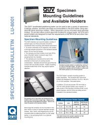
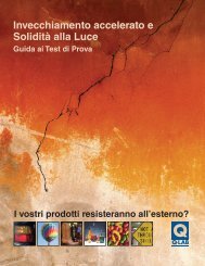
Fog (Spray) Environment: Salt fog application<br />
can take place in a B117 type test chamber or be<br />
done by hand in a labora<strong>to</strong>ry ambient environment.<br />
The fog nozzle should be such that the solution<br />
is a<strong>to</strong>mized in<strong>to</strong> a fog or mist. Commonly, in<br />
addition <strong>to</strong> NaCl, the electrolyte solution contains<br />
other chemicals <strong>to</strong> simulate acid rain or other industrial<br />
corrosives. Figure 2 shows a chamber in<br />
the fog mode.<br />
Humid Environment: CCT procedures often<br />
call for high humidity enviroments. Typically they<br />
specify 95 <strong>to</strong> 100% RH. These may be achieved<br />
by using ASTM D 2247. 11 As an alternative, a B<br />
117 chamber may sometimes be used <strong>to</strong> apply a<br />
pure water fog. Figure 3 shows a Q-Fog operating<br />
in the humidity mode.<br />
Dry-Off Environment: A dry-off environment<br />
may be achieved in an open labora<strong>to</strong>ry or inside<br />
a chamber. The area should be maintained with<br />
enough air circulation <strong>to</strong> avoid stratification and <strong>to</strong><br />
allow drying of the material. The definition of “dryoff”<br />
can be problematic. There is disagreement<br />
on whether a specimen should be considered dry<br />
when the surface is dry, or when the specimen has<br />
dried throughout. As corrosion products build up,<br />
the time necessary <strong>to</strong> achieve full dry-off may increase.<br />
Figure 4 shows Q-Fog dry-off.<br />
Corrosive Immersion Environment: This environment<br />
would normally consist of an aqueous<br />
solution with an electrolyte at a specified concentration,<br />
typically up <strong>to</strong> 5%. Typical pH is 4 <strong>to</strong> 8 and<br />
temperature is usually specified. The solution will<br />
become contaminated with use, so it should be<br />
changed on a regular basis.<br />
Water Immersion Environment: Distilled or<br />
deionized water should be used. ASTM D 1193 12<br />
provides useful guidance on water purity. The immersion<br />
container should be made of plastic or<br />
other inert material. Acidity of the bath should be<br />
within a pH range of 6 <strong>to</strong> 8. Temperature should be<br />
24°C ±3°C. Conductivity should be < 50 mmho/<br />
cm at 25°C.
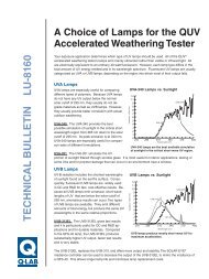
Figure 1<br />
Q-Fog Performing the<br />
Fog Function<br />
Figure 2<br />
Q-Fog Operating the<br />
Humidity Function<br />
Figure 3<br />
Q-Fog Showing the<br />
Dry-Off Environment
Guidelines for CCT <strong>Testing</strong><br />
Because CCT tests are often complicated, multistep<br />
exposures, the procedures themselves can<br />
often confound the researcher. The following<br />
guidelines are intended <strong>to</strong> aid the user in understanding<br />
the possible sources of variability in CCT<br />
exposures. The guidelines are also intended <strong>to</strong><br />
assist in obtaining good inter-labora<strong>to</strong>ry agreement<br />
of results.<br />
Use of Reference Specimens<br />
Whenever possible, reference specimens (specimens<br />
of known performance in the test conducted)<br />
should be tested concurrently with the actual<br />
specimens under test. Preferably, more than one<br />
reference specimen will be used and the references<br />
chosen will bracket the test specimen’s expected<br />
performance. The references will allow the<br />
normalization of test conditions during repeated<br />
running of the test and will also guide comparisons<br />
of test results from different repeats of the test.<br />
Preparation of Test Specimens<br />
It is common practice <strong>to</strong> scribe or chip coated<br />
test samples before exposure <strong>to</strong> the CCT. This<br />
provides a break in the coating which accelerates<br />
corrosion. When a gravelometer is used, the procedure<br />
shown in D3170 13 is recommended.<br />
There is a growing body of evidence indicating<br />
that differences in scribe depth can significantly<br />
affect the CCT test results. This is particularly important<br />
for galvanized substrates. In most cases,<br />
the scribe should penetrate in<strong>to</strong> the base metal. It<br />
is especially important that the specific scribe <strong>to</strong>ol<br />
be reported, since scribe geometry can also affect<br />
results. A microscope may be useful for characterizing<br />
the scribe damage. A scribing method is<br />
described in ASTM D1654. 14<br />
Exposure Precautions<br />
In addition <strong>to</strong> the precautions specified in B117,<br />
the multi-functional nature of CCT exposures adds<br />
<strong>to</strong> the potential problems in the area of repeatability<br />
and reproducibility of results.<br />
Chamber Loading Level: Chambers that are<br />
loaded <strong>to</strong> capacity will normally take longer <strong>to</strong><br />
make transitions between temperatures than will<br />
lightly loaded chambers. Chambers should be<br />
loaded evenly <strong>to</strong> maintain good air flow during the<br />
test.<br />
Transition (Ramp) Time: Transition time can be<br />
a fac<strong>to</strong>r affecting results in both manual and au<strong>to</strong>mated<br />
exposures. In manual exposures, transition<br />
time is the time that it takes <strong>to</strong> move the test<br />
specimens from one environment or exposure<br />
condition <strong>to</strong> another. In au<strong>to</strong>mated chambers,<br />
transition time refers <strong>to</strong> the time it takes the machine<br />
<strong>to</strong> change the exposure conditions inside<br />
the chamber. Au<strong>to</strong>mated chambers can be expected<br />
<strong>to</strong> give more predictable and reproducible<br />
transitions than manual exposures. The effect of<br />
transition times on test results still needs <strong>to</strong> be<br />
studied further. Therefore, as much as is practical,<br />
transition times should be moni<strong>to</strong>red and reported.<br />
Transition time can be expected <strong>to</strong> vary, depending<br />
upon:<br />
• Variability in ambient conditions<br />
• Variability in manual operational procedures<br />
• Type of equipment used<br />
• Cabinet loading<br />
13. D 3170, Standard Test Method for Chip Resistance of Coatings.<br />
14. D 1654, Method for Evaluation of Painted or Coated Specimens Subjected <strong>to</strong> Corrosive Environments.<br />
Fog Deposition and Uniformity: In conventional<br />
salt spray tests, the uniformity of fog dispersion is<br />
typically determined by collecting the fog fall-out<br />
at various positions around the chamber. Unlike<br />
B117, moni<strong>to</strong>ring of CCT fog deposition rates cannot<br />
be accomplished while the test is operating.<br />
This is because most CCT exposures specify relatively<br />
short fog cycles. Consequently, <strong>to</strong> determine<br />
the fog dispersion uniformity in a CCT tester, it is<br />
necessary <strong>to</strong> collect the fog fall-out between tests<br />
in a special continuous spray run of at least 16<br />
hours. See section Method B117 for detailed instructions<br />
on fog collection.<br />
Test Interruptions: Whenever a test must be<br />
interrupted, the test panels should be s<strong>to</strong>red under<br />
the least corrosive conditions available. All<br />
interruptions and handling of panels should be<br />
reported.
Reporting<br />
In addition <strong>to</strong> all of the usual test conditions that<br />
need <strong>to</strong> be reported in conventional salt spray<br />
tests, CCT test reports should include:<br />
• Ramp time for all transitions in au<strong>to</strong>mated<br />
cabinet tests<br />
• Loading (i.e., number samples) of all<br />
au<strong>to</strong>mated cabinets<br />
• Daily range and mean temperature and<br />
relative humidity for the labora<strong>to</strong>ry room<br />
where “ambient” conditions are maintained<br />
in manual tests<br />
Advantages of Au<strong>to</strong>mated CCT<br />
<strong>Cyclic</strong> corrosion test methods were originally<br />
developed as labor intensive manual procedures.<br />
Au<strong>to</strong>mated, multi-functional chambers are now<br />
available and can perform CCT tests in a single<br />
chamber. Some of the advantages of au<strong>to</strong>mated<br />
systems are that they:<br />
• Eliminate manual moving of test specimens<br />
from one chamber <strong>to</strong> another<br />
• Eliminate laborious spraying of test<br />
specimens<br />
• Eliminate variability in results from excessive<br />
specimen handling<br />
• Allow more predictable transition times<br />
Common <strong>Cyclic</strong> <strong>Corrosion</strong><br />
Test Cycles<br />
The following cycles are in common use. This list<br />
is not comprehensive. The conditions shown below<br />
are merely a summary of the full instructions<br />
found in the various specifications, test methods<br />
and practices. Consult the actual documents for<br />
more complete instructions, warnings, etc.<br />
Other cycles may be more appropriate for your<br />
application. SAE J156315 is particularly useful as<br />
a source of guidance for cyclic testing.<br />
Prohesion Cycle<br />
The Prohesion test was developed in England<br />
for industrial maintenance coatings applications.<br />
Prohesion also has a reputation as a good test for<br />
filiform corrosion.<br />
The Prohesion electrolyte solution is much more<br />
dilute than traditional salt fog. In addition, the<br />
spray a<strong>to</strong>mizing air is not saturated with water.<br />
Exposure conditions include:<br />
Electrolyte Solution 0.05% sodium chloride<br />
& 0.35% ammonium<br />
sulfate<br />
Solution Acidity pH between 5.0 and 5.4<br />
The Prohesion exposure cycle is:<br />
1 hour Salt fog application at<br />
25°C (or ambient)<br />
1 hour Dry Off at 35°C (The<br />
dry-off is achieved by<br />
purging the chamber<br />
with fresh air, such that<br />
within 3/4-hour all visible<br />
droplets are dried off of<br />
the specimens.)<br />
Repeat<br />
15. J1563, Guidelines for <strong>Lab</strong>ora<strong>to</strong>ry <strong>Cyclic</strong> <strong>Corrosion</strong> Test Procedures for Painted Au<strong>to</strong>motive Parts.
<strong>Corrosion</strong>/Weathering Cycle Au<strong>to</strong>motive CCT Exposures<br />
For industrial maintenance coatings, the addition<br />
of UV has been found useful for improving correlation<br />
on some formulations. 16, 17 This is because UV<br />
damage <strong>to</strong> a coating can make it more vulnerable<br />
<strong>to</strong> corrosion. The <strong>Corrosion</strong>/Weathering Cycle<br />
consists of one week of Prohesion alternating with<br />
one week of QUV exposure.<br />
Electrolyte Solution 0.05% sodium chloride<br />
& 0.35% ammonium<br />
sulfate<br />
Solution Acidity pH between 5.0 and 5.4.<br />
Typical Duration 2,000 hours<br />
The <strong>Corrosion</strong>/Weathering exposure cycle is:<br />
1 hour Salt fog application at<br />
25°C (or ambient)<br />
1 hour Dry Off at 35°C<br />
(The dry-off is achieved<br />
by purging the chamber<br />
with fresh air, such that<br />
within 3/4-hour all visible<br />
droplets are dried off of<br />
the specimens.)<br />
Repeat for one week, then manually move the<br />
samples <strong>to</strong> a QUV Accelerated Weathering Tester<br />
and expose at the following cycle:<br />
4 hours UV exposure, UVA-340<br />
lamps, 60°C<br />
4 hours Condensation (pure<br />
water), 50°C<br />
Repeat for one week<br />
Manually move the samples <strong>to</strong> a CCT tester and<br />
repeat the whole procedure.<br />
The au<strong>to</strong>motive industry has taken the lead in<br />
researching cyclic corrosion tests. Consequently,<br />
most of the CCT procedures are geared <strong>to</strong>ward<br />
au<strong>to</strong>motive applications.<br />
GM 9 0P/B. According <strong>to</strong> the research done<br />
by the SAE ACAP Committee and the AISI, this<br />
is currently considered one of the preferred CCT<br />
methods for au<strong>to</strong>motive cosmetic corrosion<br />
(painted or precoated metals). GM9540P/B<br />
requires a 16 hour work day or an au<strong>to</strong>matic<br />
cycling test chamber. If performed manually,<br />
a sprayer is used <strong>to</strong> mist the samples until all<br />
areas are thoroughly wet. Parts should be visibly<br />
dry before each mist application. If performed<br />
manually, the samples should be left at the<br />
ambient conditions over the weekend. There are<br />
au<strong>to</strong>mated testers available that will perform this<br />
exposure in a single chamber.<br />
The GM9540P/B exposure conditions include:<br />
Electrolyte Solution 0.9% NaCl, 0.1% CaCl2<br />
& 0.25 NaHCO3<br />
Solution Acidity pH between 6.0 and 8.0.<br />
Typical Durations 80 cycles (1,920 hours)<br />
The GM9540P/B exposure cycle is as follows:<br />
– Thorough Salt Mist<br />
Application<br />
90 minutes Ambient Conditions<br />
(25°C, 30 - 50% RH)<br />
– Thorough Salt Mist<br />
Application<br />
90 minutes Ambient Conditions<br />
(25°C, 30 - 50% RH)<br />
– Thorough Salt Mist<br />
Application<br />
90 minutes Ambient Conditions<br />
(25°C, 30 - 50% RH)<br />
– Thorough Salt Mist<br />
Application<br />
210 minutes Ambient Conditions<br />
(25°C, 30 - 50% RH)<br />
8 hours Humidity (95 - 100% RH)<br />
8 hours Dry Off (60°C,
Japanese Au<strong>to</strong>motive <strong>Cyclic</strong><br />
<strong>Corrosion</strong> Tests<br />
The Japanese have developed a number of cyclic<br />
corrosion tests. Most are primarily for au<strong>to</strong>motive<br />
applications.<br />
CCT-1. CCT-1 is specified by some Japanese au<strong>to</strong>motive<br />
manufacturers. It is also known as CCT-<br />
A. The CCT-1 exposure conditions include:<br />
Electrolyte Solution 5% sodium chloride<br />
Acidity Not specified<br />
Typical Duration: 200 cycles (1,600 hours)<br />
The CCT-1 exposure cycle is:<br />
4 hours Salt fog application at<br />
35°C<br />
2 hours Dry Off at 60°C,<br />
95% RH<br />
Repeat<br />
CCT- . CCT-4 is specified by some Japanese<br />
au<strong>to</strong>motive manufacturers. In the SAE and AISI<br />
research projects, CCT-4 was shown <strong>to</strong> be one<br />
of the exposures that best correlated with actual<br />
vehicle corrosion results. There are no special<br />
provisions for testing over the weekend. CCT-4<br />
exposure conditions include:<br />
Electrolyte Solution 5% sodium chloride<br />
Solution Acidity not specified<br />
Typical Duration 50 cycles (1,200 hours)<br />
The CCT-4 exposure cycle is:<br />
10 minutes Salt fog application at<br />
35°C<br />
155 minutes Dry Off at 60°C<br />
75 minutes Humidity at 60°C,<br />
95% RH<br />
160 minutes Dry Off at 60°C<br />
80 minutes Humidity at 60°C,<br />
95% RH<br />
160 minutes Dry Off at 60°C<br />
80 minutes Humidity at 60°C,<br />
95% RH<br />
160 minutes Dry Off at 60°C<br />
80 minutes Humidity at 60°C,<br />
95% RH<br />
160 minutes Dry Off at 60°C<br />
80 minutes Humidity at 60°C,<br />
95% RH<br />
160 minutes Dry Off at 60°C<br />
80 minutes Humidity at 60°C,<br />
95% RH<br />
Repeat
Acid Rain CCT<br />
This procedure, intended <strong>to</strong> simulate an acid<br />
rain exposure, is a modification of the Japanese<br />
Au<strong>to</strong>mobile Standards Organization (JASO) test<br />
method M609 for au<strong>to</strong>motive corrosion. Acid<br />
Rain CCT exposure conditions include:<br />
Electrolyte Solution 5% (wt) NaCl, 0.12%<br />
(vol) HNO3, 0.173%<br />
(vol) H2SO4, 0.228%<br />
(wt) NaOH<br />
Solution Acidity pH of 3.5<br />
The Acid Rain CCT exposure cycle is:<br />
2 hours Fog at 35°C<br />
4 hours Dry-off at 60°C,<br />
less than 30% RH<br />
2 hours Wet/humid at 50°C,<br />
over 95% RH<br />
Acid Rain CCT specifies transition times<br />
between environments as follows:<br />
Fog <strong>to</strong> Dry within 30 minutes<br />
Dry <strong>to</strong> Wet within 15 minutes<br />
Wet <strong>to</strong> Fog within 30 minutes<br />
Summary<br />
There are a large number of cyclic corrosion procedures<br />
<strong>to</strong> choose from. Each has advantages and<br />
limitations. Some researchers prefer fog environments<br />
<strong>to</strong> immersion. Some prefer specialized electrolyte<br />
solutions <strong>to</strong> simulate acid rain. Many prefer<br />
the advantages of au<strong>to</strong>mated chambers. The relative<br />
advantages of various exposure temperatures,<br />
durations, and sequences remain somewhat controversial<br />
and researchers will, no doubt, continue <strong>to</strong><br />
modify cycle times and adjust corrosive solutions.<br />
However, there is a strong consensus that, for most<br />
materials, cyclic corrosion testing gives more realistic<br />
results than traditional salt spray.<br />
Q-<strong>Lab</strong> Corporation www.q-lab.com<br />
Q-<strong>Lab</strong> Headquarters<br />
& Instruments Division<br />
Cleveland, Ohio 44145 USA<br />
Tel. +1-440-835-8700<br />
Fax +1 440-835-8738<br />
info@q-lab.com<br />
Q-<strong>Lab</strong> UK, Ltd.<br />
Bol<strong>to</strong>n, England<br />
Tel. +44 (0) 1204-861616<br />
Fax +44 (0) 1204-861617<br />
info.eu@q-lab.com<br />
Weathering Research Service<br />
Q-<strong>Lab</strong> Florida Q-<strong>Lab</strong> Arizona<br />
Homestead, Florida USA Buckeye, Arizona USA<br />
Tel. +1-305-245-5600 Tel. +1-623-386-5140<br />
Fax +1-305-245-5656 Fax +1-623-386-5143<br />
q-lab@q-lab.com q-lab@q-lab.com<br />
Q-<strong>Lab</strong> Germany / Q-<strong>Lab</strong> Deutschland GmbH<br />
Düsseldorf, Germany<br />
Tel. +49 (0) 211 50080255<br />
Fax +49 (0) 211 50657011<br />
info.de@q-lab.com<br />
Q-<strong>Lab</strong> China / 美国Q-<strong>Lab</strong>公司中国代表处<br />
电话:+86-21-58797970, +86-21-56030380<br />
传真:+86-21-58797960<br />
info.cn@q-lab.com<br />
LF -8144.1<br />
© 2009 Q-<strong>Lab</strong> Corporation.<br />
All Rights Reserved.