SWS - Stemco Quick Reference 2011 - CARQUEST Auto Parts
SWS - Stemco Quick Reference 2011 - CARQUEST Auto Parts
SWS - Stemco Quick Reference 2011 - CARQUEST Auto Parts
- No tags were found...

You also want an ePaper? Increase the reach of your titles
YUMPU automatically turns print PDFs into web optimized ePapers that Google loves.
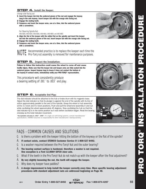
STEP 4. Install the Keeper:Orange side facing out1 Insert the keeper tab into the undercut groove of the nut and engage the keywaytang in the axle keyway. Insert keeper tab with the orange side facing out.2 Engage the mating teeth.3 Compress and insert the keeper arms, one at a time, into the undercut groovewith a screwdriver.For Steering Spindle Nut448-4836, 448-4839, 448-4840, 448-4863, 448-4864, and 448-48651 Align the flat of the keeper with the milled flat on the spindle and insert the keepertab into the undercut groove of the nut. Insert keeper tab with the orange side facing out.2 Engage the mating teeth.3 Compress and insert the keeper arms, one at a time, into the undercut groovewith a screwdriver.NOTERecommended practice is to replace the keeper each time thePro-Torq nut assembly is removed for maintenance purposes.STEP 5. Inspect the Installation:Failure to follow this instruction could cause the wheel to come off and causebodily injury. Make sure that the keeper tab and keeper arms are fully seated into theundercut groove. Inspect keyway tang to insure it does not contact the bottom ofthe keyway If contact exists, immediately notify your PRO-TORQ® representative.This procedure will consistently producea bearing setting of .001˝ to .003˝ end play.STEP 6. Acceptable End Play:The dial indicator should be attached to the hub or brake drum with its magnetic base.Adjust the dial indicator so that its plunger is against the end of the spindle with its line ofaction approximately parallel to the axis of the spindle. Grasp the wheel or hub assemblyat the 3 o’clock and 9 o’clock positions. Push and pull the wheel-end assembly in and outwhile oscillating the wheel approximately 45 degrees. Stop oscillating the hub so that thedial indicator tip is in the same position as it was before oscillation began. Read the bearingend-play as the total indicator movement.*Acceptable end-play is .001”- .005”. For single nut self-locking systems, consult manufacturers’specifications. STEMCO assumes no responsibility for other manufacturers’ bearing warranty.FAQS - COMMON CAUSES AND SOLUTIONSQ. Is there a problem with the keeper hitting the bottom of the keyway or the flat of the spindle?A. If contact exists, contact STEMCO Customer Service @ 1-800-527-8492.Q. Is a washer required between the Pro-Torq® Nut and the outer bearing?A. The bearing contact surface is hardened, therefore a washer is not required.One exception is a Ford 12,000# SIFCO steer axle.Q. What if the teeth in the Pro-Torq® Nut do not match-up with the keeper after the final adjustment?A. By very slightly loosening the nut, the teeth will engage the keeper.Q. Why does my keeper have paddles?A. A design improvement to help install the keeper correctly every time. More specific bearing adjustmentprocedures with standard adjustment nuts are addressed beginning on Page 48.PRO TORQ ® INSTALLATION PROCEDURE<strong>2011</strong> Order Entry 1-800-527-8492 Fax 1-800-874-4297 55