Base Station Antenna Systems 2008 Product Selection Guide - AVW
Base Station Antenna Systems 2008 Product Selection Guide - AVW
Base Station Antenna Systems 2008 Product Selection Guide - AVW
- No tags were found...

Create successful ePaper yourself
Turn your PDF publications into a flip-book with our unique Google optimized e-Paper software.
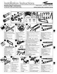
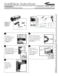
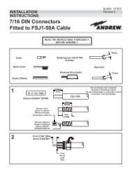
Applications/Engineering Notes<strong>Base</strong> <strong>Station</strong> <strong>Antenna</strong> Materials and Mechanical CharacteristicsIsolation in dBIsolation in dBIsolation Provided by <strong>Antenna</strong> SeparationATTENUATION PROVIDED BY VERTICAL SEPARATION OF DIPOLE ANTENNAS7060504030202000 MHz850 MHz450 MHz160 MHz101 2 3 5 10 20 30 50 100(0.3) (0.61) (0.91) (1.52) (3.05) (6.1) (9.14) (15.24) (30.48)<strong>Antenna</strong> Spacing in Feet (Meters)(Measured between antenna centers)75 MHz40 MHzThe values indicated by these curves are approximate because of coupling that exists between the antenna and transmission line.Curves are based on the use of half-wave dipole antennas. The curves will also provide acceptable results for gain type antennas if(1) the spacing is measured between the physical center of the tower antennas and (2) one antenna is mounted directly above theother, with no horizontal offset (exactly collinear). No correction factor is required for the antenna gains.ATTENUATION PROVIDED BY HORIZONTAL SEPARATION OF DIPOLE ANTENNAS8070605040302000 MHz850 MHz450 MHz150 MHz70 MHz50 MHz30 MHzHeavy hardware such as clamps, orientationmounts and offset brackets, should be steel,protected with hot dip galvanize finish, or castaluminum—depending on the application.Heavy directive arrays should incorporateinto the mount a convenient means oforientation with positive position locking.Clamps and mounts should be heavy duty inorder to transfer the full antenna load to thesupport tower or mast.Stainless steel locking bands of the radiatorhose type are very suitable for manyattachments provided that they are properlyapplied. The draw-up screws should alwaysbe positioned so as to draw down against afirm member (preferably round) in order toforce locking and holding of the screw to theband slots. Properly applied, these clampingbands are extremely strong and will maintainclamping force indefinitely. They offer aconvenient means of fastening to various sizesand shapes of towers and masts.Painting <strong>Base</strong> <strong>Station</strong> <strong>Antenna</strong>sTo help antennas blend into the backgroundand make zoning easier, many customersdesire to paint the entire antenna. This can beeasily accomplished if a non-metallic basedpaint is used and smooth surfaces are slightlyroughed for better adhesion. For moreinformation please visit our website atwww.andrew.com/products/antennas/bsaand select BSA Technical Literature.2010 20 30 50 100 200 300 500 1000(3.05) (6.1) (9.14) (15.24) (30.48) (60.96) (91.44) (152.4) (304.8)<strong>Antenna</strong> Spacing in Feet (Meters)Curves are based on the use of half-wave dipole antennas. The curves will also provide acceptable results for gain type antennas if(1) the indicated isolation is reduced by the sum of the antenna gains and (2) the spacing between the gain antennas is at least 50 ft.(15.24 m) (approximately the far field).132Andrew Wireless Solutions www.andrew.com