Base Station Antenna Systems 2008 Product Selection Guide - AVW
Base Station Antenna Systems 2008 Product Selection Guide - AVW
Base Station Antenna Systems 2008 Product Selection Guide - AVW
- No tags were found...

You also want an ePaper? Increase the reach of your titles
YUMPU automatically turns print PDFs into web optimized ePapers that Google loves.
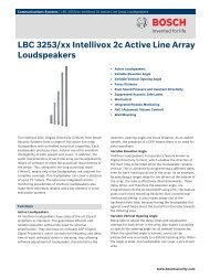
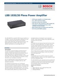
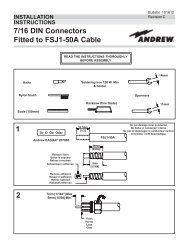
Applications/Engineering Notes<strong>Antenna</strong> FundamentalsBack Lobe160170180190170180190130140150160200150140120120130110Front-to-BackRatio110100200210340330220320230310240300250260 270 280290100909080Horizontal PatternPolar Plot Center = -40 dB-3 dB level 5 dB/radial division10°/angular division80707060605050404030Side LobesNulls302020340100350100350Half PowerBeamwidth Figure 11 Horizontal Pattern Polar Plot showing HPBW and Front-to-Back RatioMain LobeMain Lobe MaximumNull FillFront-to-Back RatioThe front-to-back ratio is the ratio of the maximum directivity of anantenna (usually at = 0°, = 0° in the altazimuth coordinatesystem) to its directivity in a rearward direction antenna (usually at = 0°, = 180° in the altazimuth coordinate system). Figure 11shows the HPBW and front-to-back ratio for a typical horizontalpattern.Side Lobes and NullsA typical vertical pattern is shown in Figure 12. The main lobe (ormain beam or major lobe) is the lobe in which the direction of maximumradiation occurs. A number of minor lobes are found aboveand below the main lobe. These are termed side lobes. Betweenthese side lobes are directions in which little or no radiation occurs.These are termed nulls. Nulls may represent a 30 or more dBreduction (less than one-thousandth the energy of the main beam)in received signal level in that direction.Techniques exist to lower upper side lobes and redirect some ofthe radiating energy and fill in nulls. This is termed null fill. Often,the consequence of doing this is to widen the main lobe and thuslower the directivity and reduce the antenna’s gain.Cross-Polarization Ratio (CPR)CPR is a comparison of the co-polarized vs. cross-polarized patternperformance of a dual-polarized antenna generally over the sectorof interest (alternatively over the 3 dB beamwidth).It is a measure of the ability of a cross-polarized array to distinguishbetween orthogonal waves. The better the CPR, the betterthe performance of polarization diversity.210330220320230240250260 270 280290300310Polar Plot Center = -40 dB5 dB/radial division10/angular division Figure 12 Elevation Pattern Polar Plot showing Pattern Parameters120° 120°TypicalDirectedDipole Cross-Pol Ratio (CPR)Co-PolarizationCross-Polarization (Source at 90°)122Andrew Wireless Solutions www.andrew.com